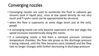
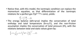
Nozzles are tubes that aim to increase the speed of an outflow and control its direction and shape. Nozzle flow generates reaction forces from changes in momentum. In rockets, ejecting mass backwards through a nozzle creates thrust. Nozzles transform thermal or pressure energy into kinetic energy and momentum. Nozzle flow is rapid and nearly adiabatic. Real nozzle flow departs from ideal due to non-adiabatic effects and viscous dissipation. Nozzle area ratio is defined as the exit area over throat area.

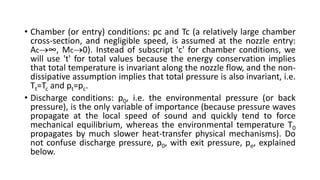
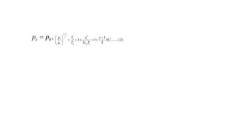
![• The objective is to find the flow conditions at the exit [pe,Te,ve] for a
given set of the above parameters [Ae,γ ,R ,p c,Tc,p0], so that
• If the nozzle flow is subsonic, then the exit pressure coincides with
the discharge pressure, pe=p0
• other variables would be obtained from the isentropic relations at
steady state
,
e
e e e e e
e
P
m v A v A
RT
F ,
e
mv
......(1)
e
e
e
v
M
RT
](https://image.slidesharecdn.com/nozzel-230614164438-6152941d/85/PET-512-NOZZEL-pptx-8-320.jpg)