The document provides an overview of a petrochemical complex located in northern India. It consists of several key units: (1) a gas processing unit to recover ethane and propane from natural gas, (2) a gas cracker unit to produce ethylene and propylene, and (3) downstream polyethylene production units. Safety procedures at the plant include wearing protective equipment, locating assembly points, and pushing emergency buttons. Temperature and pressure sensors are discussed, along with calibration devices. The document concludes with descriptions of programmable logic controllers and distributed control systems used to remotely monitor and control industrial processes.
The document provides information about a seminar on the IOCL complex refinery located in Panipat, Haryana. It discusses the instrumentation used at the refinery to monitor and control various processes. It describes the main control system used, various temperature measurement techniques like thermocouples, thermistors, and RTDs. It also discusses level measurement using differential pressure, capacitance, displacers/floats, and bubblers. Additional topics covered include pressure measurement, flow measurement using orifice plates and venturi meters, and an introduction to programmable logic controllers.
The document provides an overview of instrumentation and control systems used in a thermal power plant. It describes the key components measured including pressure, temperature, flow, level and vibration. It then explains the various sensors and instruments used to measure these variables, including bourdon tubes, thermocouples, RTDs, orifice plates, and analyzers. It also describes the control room and various labs used for maintenance and calibration of instrumentation. The objectives of instrumentation are listed as efficient, economic and safe operation of the plant along with pollution control.
This document provides an overview of instrumentation and control systems used in thermal power plants. It discusses the key components measured which include pressure, temperature, flow, level, expansion, vibration, and flue gas analysis. Common sensors used for measurement such as bourdon tubes, diaphragms, bellows, thermocouples, RTDs, orifice plates, and analyzers are outlined. The functions of instrumentation include measurement, control, monitoring, operation, and protection to efficiently, economically and safely operate the plant while controlling pollution. Laboratories in the control and instrumentation department are described including their equipment for manometry, protection and interlocking, automation, electronics, and water treatment.
Thermal plant instrumentation and controlShilpa Shukla
This document provides an overview of instrumentation and control systems used in a thermal power plant. It discusses the key components measured including pressure, temperature, flow, level, vibration and flue gas analysis. It describes the various sensors and instruments used to measure these variables, including bourdon tubes, diaphragms, bellows, thermocouples, RTDs, orifice plates, and analyzers. It also discusses the control and monitoring systems, laboratories, and pollution control systems used in thermal power plants.
odometer and some terms in instrumentationBagja Tirta
The document discusses various measurement instruments and their characteristics. It defines an odometer as an instrument that measures distance traveled by vehicles. It also defines a tripmeter, which differs from an odometer in that it can be reset to measure individual trips or parts of a trip. It then lists and describes 14 different measurement instruments and their functions, including their accuracy, precision, range, resolution, and more. It provides photos of some of the instruments discussed.
odometer and some terms in istrumentationBagja Tirta
The document discusses various measurement instruments and their characteristics. It defines an odometer as an instrument that measures distance traveled by vehicles. It also defines a tripmeter, which differs from an odometer in that it can be reset to measure individual trips or parts of a trip. It then lists and describes 14 different measurement instruments and their functions, including thermocouples, RTDs, pressure transmitters, data loggers, valves, and analog-to-digital converters and digital-to-analog converters. It includes photos illustrating some of these instruments.
Ravi Singh completed an industrial training at NTPC Badarpur power station. He thanks the staff who provided guidance during his training, particularly Mr. Mahendra Singh Chabra and Mr. Anant Kumar Varshney. NTPC was established in 1975 and has expanded significantly, with plans to reach 75,000 MW of capacity by 2017. Badarpur power station meets over 24% of Delhi's electricity needs with its 720 MW installed capacity. The report provides overviews of the basic principles of thermal power generation, control and instrumentation labs, distributed control systems, and other key components and processes at NTPC power stations.
This document discusses temperature and flow measurement. It begins by defining temperature and the common units used to measure it. There are two main methods for measuring temperature - electrical and non-electrical. Electrical methods include thermocouples, thermistors, and RTDs, which convert temperature into an electrical signal. Non-electrical methods include infrared thermometers and glass thermometers. The document also defines flow and common flow measurement units. Main flow measurement devices are discussed, including orifice plates, vortex meters, pitot tubes, and magnetic and turbine flow meters. These devices are used across industries like oil/gas, water treatment, and manufacturing.
Experimental investigate to obtain the effectiveness of regenerator using Air.IJESFT
The regenerator is a kind of heat exchanger that provides a way to get the gas to the low temperature with as much potential work (cooling power) as possible without carrying a lot of heat with it. It doesn’t put heat in or out of the system but it absorbs heat from the gas on one part of the pressure cycle and returns heat to the gas on the other part.
More recent applications of regenerators in cryogenic systems can be found in small cryogenic refrigerators (cryocoolers). Systems such as the Stirling Gifford-McMahon, pulse tube, Solvay, Vuilleumier and magnetic cycle refrigerators all use either a static or rotary regenerator. In fact, the success these coolers have achieved is directly related to the characteristics of compact size and efficiency of the regenerator.
Regenerator effectiveness of 99% results in 21% loss of refrigeration effect, similarly regenerator effectiveness of 98% results in 42% loss of refrigeration effect, with refrigeration effectiveness of 95.238% the loss of refrigeration is 100%. i.e. no net cooling is produced.
In cryogenic applications the regenerator is typically made up of 100 to 500 meshes SS 304, Phosphorous bronze screens or small lead spheres (150 to 300 micro meters) are used, that are tightly packed together and held in place on either end in the same manner.
To develop experimental setup at our laboratory level by using air as working fluid and find out the effectiveness of various regenerative materials is basic goal of this work.
The document describes the development of an experimental test rig for testing a dual fuel and diesel engine. Key components of the test rig include an L-shaped channel frame, Bakelite boards for mounting instrumentation, and panels for controls and loads. Instruments such as a voltmeter, ammeter, tachometer, temperature indicators, and fuel flow meters were installed to measure voltage, current, RPM, temperature, and fuel consumption. The test rig was designed to provide measurements needed to analyze parameters like power, speed, temperature, and fuel efficiency of the engine.
This document describes the design of an air conditioning system for a Volvo bus. It discusses the components of an automotive air conditioning system including a compressor, condenser, expansion device, evaporator, and accumulator. The document then provides details of the experimental setup used, which models these components in a closed refrigeration loop using R-134a refrigerant. Calculations are shown to determine the cooling load required for the bus based on parameters like occupancy, glass area, temperature conditions, and heat sources. The cooling load is calculated to be 1.13 kW, requiring a system with 8.25 tons of cooling capacity.
International Journal of Engineering Research and DevelopmentIJERD Editor
This document describes a system for controlling the temperature of a shell and tube heat exchanger using a TwinCAT PLC. The system uses sensors to measure the outlet temperature of the tube fluid and a control valve regulates the flow of cold water to maintain the outlet at the setpoint temperature. The TwinCAT PLC implements a control algorithm that compares the measured temperature to the setpoint and sends signals to adjust the control valve position. Testing showed the system successfully maintained the outlet temperature at the desired setpoint. The automated temperature control reduces maintenance costs compared to a non-automated system.
This document discusses various process control measurement techniques and final control elements. It describes common methods for measuring temperature, level, pressure, flow, and chemical analysis including thermocouples, RTDs, float systems, differential pressure, capacitive devices, ultrasonics, turbines, electromagnetic and Coriolis flow meters. Final control elements convert control signals into actions on process variables through signal conversion, actuators and control elements like valves.
The document provides information about calibrating different types of thermocouples using a thermocouple calibration apparatus. It discusses that a thermocouple measures the temperature difference between its two junctions by producing a voltage proportional to the temperature differential. The experiment involves calibrating thermocouples like K-type and T-type using the calibration apparatus and comparing the readings to known standards to determine accuracy. The summary provides an overview of the key aspects and goal of the thermocouple calibration process discussed in the document.
Vikalo Instruments is leading manufacturing company to provide Process Engineering Solutions with our industrial products such as Pressure & Temperature Gauges,Thermocouple,Rtd,Industrial Heater and other process equipment in the Instrumentation Engineering filed.
INTEGRATION OF WATER CHILLER AND AIR COOLERIRJET Journal
This document discusses the integration of a water chiller and air cooler unit using a single vapor compression refrigeration system. A T-joint with a split valve is used to direct refrigerant to the two evaporators. An Arduino controls the split valve position based on temperature sensors to allocate more refrigerant to the water chiller or air cooler as needed. Computational fluid dynamics analysis shows the pressure and velocity of refrigerant flowing through the T-joint with minimal pressure drop. Integrating the units could reduce costs compared to separate systems and be useful for applications like bus stations.
This document discusses automation in the pharmaceutical industry. It defines automation and describes its advantages such as improved quality, reduced costs, and increased safety. Automation can occur at various stages of manufacturing like material handling, production processes, and quality control. The document also discusses process control and variables like temperature, pressure, and flow that are important to measure. It provides examples of automation in tablet manufacturing that can improve material handling and specific unit operations.
Unit-3 Instrumentation and control in mechanical engineering and other basic subject which contain instruments and their working under the syllabus of RGPV UNIVERSITY Bhopal.
Multi energy coupling system based on plc and wincceSAT Journals
Abstract The development and utilization of multi-energy coupling platform has been completed by the software of Siemens S7-200 and configuration software WinCC. PLC of Siemens is used to collect temperature, flow rate, quantity of heat, power, etc. and calculate the COP of heat pump and the system. The detecting system is composed of the slave computer PLC and the host computer WinCC. The real-time monitoring and control function are realizedbythis system.And six operational modes of the solar-ground source heat pump system are designedaccording to different external conditions, which is an effective way to make up the shortcomings of the solar energy and GSHP (Ground Source Heat Pump) individually. Key words: PLC, WinCC, Monitoring system, Operational mode
Experimental Determination of Compressibility Factors of Gasesiosrjce
The compressibility factor Z also known as the compression factor is the ratio of the molar volume of a
gas to the molar volume of an ideal gas at the same temperature and pressure. It is a useful thermodynamic
property accounting for real gas behavior. In general, deviation from ideal behavior becomes more significant
at lower temperatures and higher pressures. For gas mixtures, a gas composition must be specified while
calculating the compressibility factor.
This document discusses instrumentation and control in power plants. It begins by introducing power plants and their objectives of being economically and environmentally friendly. It then discusses the classification and types of power plants, focusing on thermal power plants. It describes the key sub-cycles and quantities that must be measured in thermal power plants, including pressure, temperature, flow, and emissions. It outlines the measurement process and locations. Finally, it provides references on power plant engineering.
This document discusses instrumentation and control in power plants. It begins by defining power plants and their objectives of being economically and environmentally friendly. It then describes the functions of instrumentation systems in power plants, which include measurement, control, operation, monitoring and protection. It focuses on thermal power plants, outlining their key sub-cycles and quantities that must be measured, such as pressure, temperature, flow and level. It details different sensor types used to measure these variables and their typical locations. Finally, it discusses the measurement process and references additional resources.
Designing and installation of low cost optimized wind monitoring systemeSAT Publishing House
IJRET : International Journal of Research in Engineering and Technology is an international peer reviewed, online journal published by eSAT Publishing House for the enhancement of research in various disciplines of Engineering and Technology. The aim and scope of the journal is to provide an academic medium and an important reference for the advancement and dissemination of research results that support high-level learning, teaching and research in the fields of Engineering and Technology. We bring together Scientists, Academician, Field Engineers, Scholars and Students of related fields of Engineering and Technology.
Converter station water-cooled pump vibration monitoring and condition assess...IJRES Journal
In High Voltage Direct Current(HVDC) Transmission Systems, high intelligence and reliability is demand more. It’s urgently necessary to run a real-time monitoring system on converter station water-cooled pump. From the functional requirements of the monitoring system, describes the structure of the proposed converter station water-cooled pump vibration signal monitoring systems, data acquisition unit of hardware and software systems. In accordance with vibration severity in GB/T 29531-2013, As a water-cooled pump monitoring and early warning threshold, based on LabVIEW, We developed a water-cooled pump monitoring system software. Test results show that the system can effectively monitor the water-cooled pump’s working conditions.
The document provides an overview of instrumentation and process control fundamentals, including key terminology. It describes a basic process control loop using a water tank example where an operator manually controls the water level by opening or closing an inlet valve. The controlled variable is the water level, which is influenced by manipulating the flow through adjustments to the inlet valve. Process control components like sensors, transmitters, controllers and final control elements are also defined.
Soot sensor to fulfill euro6 obd requirementskhedayat
1) The document describes a novel soot sensor design with a single layer sensing element that overcomes challenges with traditional resistive soot sensors.
2) The single layer design integrates the heating and sensing functions into a simple construction, improving regeneration efficiency and enabling robust diagnostics.
3) Testing showed the single layer sensor can regenerate effectively even at high exhaust flows, requires less voltage for regeneration than conventional designs, and responds well to varying soot concentrations.
HIL Report on Refrigeration unit & BoilersAkansha Jha
Study of refrigeration unit & boilers. It involved the calculation of safe chimney height required to dispose the smoke out into atmosphere without polluting the land and the estimation of fuel amount required for an oil fired boiler per day in HIL, Rasayani.
Blood finder application project report (1).pdfKamal Acharya
Blood Finder is an emergency time app where a user can search for the blood banks as
well as the registered blood donors around Mumbai. This application also provide an
opportunity for the user of this application to become a registered donor for this user have
to enroll for the donor request from the application itself. If the admin wish to make user
a registered donor, with some of the formalities with the organization it can be done.
Specialization of this application is that the user will not have to register on sign-in for
searching the blood banks and blood donors it can be just done by installing the
application to the mobile.
The purpose of making this application is to save the user’s time for searching blood of
needed blood group during the time of the emergency.
This is an android application developed in Java and XML with the connectivity of
SQLite database. This application will provide most of basic functionality required for an
emergency time application. All the details of Blood banks and Blood donors are stored
in the database i.e. SQLite.
This application allowed the user to get all the information regarding blood banks and
blood donors such as Name, Number, Address, Blood Group, rather than searching it on
the different websites and wasting the precious time. This application is effective and
user friendly.
Build the Next Generation of Apps with the Einstein 1 Platform.
Rejoignez Philippe Ozil pour une session de workshops qui vous guidera à travers les détails de la plateforme Einstein 1, l'importance des données pour la création d'applications d'intelligence artificielle et les différents outils et technologies que Salesforce propose pour vous apporter tous les bénéfices de l'IA.
Tools & Techniques for Commissioning and Maintaining PV Systems W-Animations ...Transcat
Join us for this solutions-based webinar on the tools and techniques for commissioning and maintaining PV Systems. In this session, we'll review the process of building and maintaining a solar array, starting with installation and commissioning, then reviewing operations and maintenance of the system. This course will review insulation resistance testing, I-V curve testing, earth-bond continuity, ground resistance testing, performance tests, visual inspections, ground and arc fault testing procedures, and power quality analysis.
Fluke Solar Application Specialist Will White is presenting on this engaging topic:
Will has worked in the renewable energy industry since 2005, first as an installer for a small east coast solar integrator before adding sales, design, and project management to his skillset. In 2022, Will joined Fluke as a solar application specialist, where he supports their renewable energy testing equipment like IV-curve tracers, electrical meters, and thermal imaging cameras. Experienced in wind power, solar thermal, energy storage, and all scales of PV, Will has primarily focused on residential and small commercial systems. He is passionate about implementing high-quality, code-compliant installation techniques.
Open Channel Flow: fluid flow with a free surfaceIndrajeet sahu
Open Channel Flow: This topic focuses on fluid flow with a free surface, such as in rivers, canals, and drainage ditches. Key concepts include the classification of flow types (steady vs. unsteady, uniform vs. non-uniform), hydraulic radius, flow resistance, Manning's equation, critical flow conditions, and energy and momentum principles. It also covers flow measurement techniques, gradually varied flow analysis, and the design of open channels. Understanding these principles is vital for effective water resource management and engineering applications.
Home security is of paramount importance in today's world, where we rely more on technology, home
security is crucial. Using technology to make homes safer and easier to control from anywhere is
important. Home security is important for the occupant’s safety. In this paper, we came up with a low cost,
AI based model home security system. The system has a user-friendly interface, allowing users to start
model training and face detection with simple keyboard commands. Our goal is to introduce an innovative
home security system using facial recognition technology. Unlike traditional systems, this system trains
and saves images of friends and family members. The system scans this folder to recognize familiar faces
and provides real-time monitoring. If an unfamiliar face is detected, it promptly sends an email alert,
ensuring a proactive response to potential security threats.
Supermarket Management System Project Report.pdfKamal Acharya
Supermarket management is a stand-alone J2EE using Eclipse Juno program.
This project contains all the necessary required information about maintaining
the supermarket billing system.
The core idea of this project to minimize the paper work and centralize the
data. Here all the communication is taken in secure manner. That is, in this
application the information will be stored in client itself. For further security the
data base is stored in the back-end oracle and so no intruders can access it.
Accident detection system project report.pdfKamal Acharya
The Rapid growth of technology and infrastructure has made our lives easier. The
advent of technology has also increased the traffic hazards and the road accidents take place
frequently which causes huge loss of life and property because of the poor emergency facilities.
Many lives could have been saved if emergency service could get accident information and
reach in time. Our project will provide an optimum solution to this draw back. A piezo electric
sensor can be used as a crash or rollover detector of the vehicle during and after a crash. With
signals from a piezo electric sensor, a severe accident can be recognized. According to this
project when a vehicle meets with an accident immediately piezo electric sensor will detect the
signal or if a car rolls over. Then with the help of GSM module and GPS module, the location
will be sent to the emergency contact. Then after conforming the location necessary action will
be taken. If the person meets with a small accident or if there is no serious threat to anyone’s
life, then the alert message can be terminated by the driver by a switch provided in order to
avoid wasting the valuable time of the medical rescue team.
Software Engineering and Project Management - Software Testing + Agile Method...Prakhyath Rai
Software Testing: A Strategic Approach to Software Testing, Strategic Issues, Test Strategies for Conventional Software, Test Strategies for Object -Oriented Software, Validation Testing, System Testing, The Art of Debugging.
Agile Methodology: Before Agile – Waterfall, Agile Development.
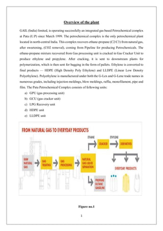
1. 1
Overview of the plant
GAIL (India) limited, is operating successfully an integrated gas based Petrochemical complex
at Pata (U.P) since March 1999. The petrochemical complex is the only petrochemical plant
located in north-central India. This complex recovers ethane-propane (C2/C3) from natural gas,
after sweetening, (CO2 removal), coming from Pipeline for producing Petrochemicals. The
ethane-propane mixture recovered from Gas processing unit is cracked in Gas Cracker Unit to
produce ethylene and propylene. After cracking, it is sent to downstream plants for
polymerization, which is then sent for bagging in the form of pallets. Ethylene is converted to
final products — HDPE (High Density Poly Ethylene) and LLDPE (Linear Low Density
Polyethylene). Polyethylene is manufactured under both the G-Lex and G-Lene trade names in
numerous grades, including injection moldings, blow moldings, raffia, monofilament, pipe and
film. The Pata Petrochemical Complex consists of following units:
a) GPU (gas processing unit)
b) GCU (gas cracker unit)
c) LPG Recovery unit
d) HDPE unit
e) LLDPE unit
Figure no.1
2. 2
FIRE AND SAFETY
Primary safety measure that we should take is never put your safety helmet off in the field
and wear safety shoes every time.
Some fire and safety guidelines:
1. In case of emergency first thing to undertake is observe the windsock which gives the
direction of the wind always run opposite to it.
2. At crisis locate the (assembly point) because they are the safest location in the plant.
3. At case if chemical falls on you immediately rush to safety showers which are
located in each unit of the plant.
4. At the time of crisis if you see fire at any point of the plant push the emergency cell
button which are present outside every
Unit.
Figure no.2
3. 3
Introduction to Sensing and Measuring devices
Temperature sensing devices
Some of the more common instruments used
Thermocouples
Resistance thermometers (RTDs)
Thermocouple:
A thermocouple is a sensor that measures temperature. It consists of two different types of
metals joined together at one end. When the junction of the two metals is heated or cooled,
a voltage is created that can be correlated back to the temperature.
Figure no.3
Working principle of thermocouple:
The thermocouple working principle is based on the Seeback Effect. This effect states that
when a closed circuit is formed by jointing two dissimilar metals at two junctions, and junctions
are maintained at different temperatures then an electromotive force (e.m.f.) is induced in this
closed circuit.
4. 4
Types of thermocouple , range and material:
Figure no.4
Resistance temperature detector (RTDs):
An RTD (Resistance Temperature Detector) is a sensor whose resistance changes as its
temperature changes. The resistance increases as the temperature of the sensor
increases. The resistance vs temperature relationship is well known and is repeatable
over time. An RTD is a passive device.
Figure no.5
5. 5
PT100:
The RTD PT100, which is the most commonly used RTD sensor, is made of platinum (PT),
and its resistance value at 0°C is 100 O. In contrast, a PT1000 sensor, also made of platinum,
has a resistance value of 1000 O at 0°C.
Working principle of RTD:
Resistance Temperature Detectors (RTD) operates on the principle that the electrical
resistance of a metal changes predictably in an essentially linear and repeatable manner with
changes in temperature. RTD have a positive temperature coefficient (resistance increases
with temperature). also Pt500 or Pt1000 RTD sensors are used.
Figure no.6
Temperature range of PT100:
Platinum resistance thermometers (PRTs) offer excellent accuracy over a wide temperature
range (from –200 to +850 °C).
Temperature transmitter:
A temperature transmitter is an electronic device used to send a temperature measurement over
two wires to the processing unit. The transmitter is responsible for converting the small
electrical signal from the temperature sensor into a more readable signal for the processing
unit.
6. 6
Figure no.7
Pressure sensing devices:
Bourdon tube pressure gauge
Diaphragm pressure gauge
Capillary pressure gauge
Bourdon tube pressure gauge:
A bourdon tube pressure gauge is a mechanical pressure measuring instrument that reads
the pressure without requiring any electrical power. It is generally used for the
measurement of pressure from 0.6 to 7000 bar (8 to 10000 psi).
Figure no.8
7. 7
Diaphragm pressure gauge:
Diaphragm pressure gauges are preferably used for low pressure ranges. Through the large
working surface of the circular, corrugated diaphragm element, small pressure ranges can be
measured reliably.
Figure no.9
Pressure unit: The pressure measure unit for the diaphragm pressure gauge is bar or psi. The
pressure may usually range from -1 to 400 bar.
Capillary pressure gauge
Capillaries are used for mounting pressure gauges, transmitters, and switches away from
the tank or pipe. This may be done for several reasons. You might wish to mount your
pressure instrument in an area with good visibility, like an instrument panel. In other cases,
it may be necessary to reduce instrument pulsation.
Figure no.10
8. 8
Calibration
Calibration is the process of configuring an instrument to provide a result for a sample
within an acceptable range. Eliminating or minimizing factors that cause inaccurate
measurements is a fundamental aspect of instrumentation design.
Deadweight tester:
A deadweight tester is a calibration standard that uses the principle of a pressure balance to
calibrate pressure measuring instruments. Deadweight testers use calibrated weights to
apply known pressures to a device under test for a simple and cost-effective solution that
covers a wide range of pressure calibrations.
Figure no.11
Pressure transmitter:
A pressure transmitter is a mechanical device that measures the expansive force of a liquid or
gaseous sample. Also known as a pressure transducer, this type of sensor is typically composed
of a pressure sensitive surface area made of steel, silicon, or other materials depending upon
the analyte's composition.
9. 9
Figure no.12
Flow sensing devices
Rotameter
Mass-flow meter
Orifice plate
Rotameter:
A rotameter is a device that measures the volumetric flow rate of fluid in a closed tube. It
belongs to a class of meters called variable-area flowmeters, which measure flow rate by
allowing the cross-sectional area the fluid travels through to vary, causing a measurable
effect.
Figure no.13
10. 10
Mass-flow meter:
A mass flow meter, also known as an inertial flow meter, is a device that measures mass
flow rate of a fluid traveling through a tube. The mass flow rate is the mass of the fluid
traveling past a fixed point per unit time.The mass flow meter does not measure the volume
per unit time (e.g. cubic meters per second) passing through the device; it measures the
mass per unit time (e.g. kilograms per second) flowing through the device. Volumetric flow
rate is the mass flow rate divided by the fluid density. If the density is constant, then the
relationship is simple.
Figure no.14
Orifice plate:
An orifice plate is a circular plate inserted into a pipe that has a hole for the flow to pass
through. The hole is smaller in diameter than the pipe, creating flow restriction and pressure
drop.
Figure no.15 (Orifice plate with flow meter)
11. 11
Level sensing devices
Glass-tube
Float type
Glass-tube:
Use of a sight glass is probably the simplest method of measuring liquid level. The sight glass
is attached to the outside of the tank so that the liquid level can be seen through the glass. The
sight glass is marked with graduations to allow the level to be measured.
Figure no.16
Float-type:
One common form of level measuring system uses a tape or servo motor which is connected
to a float. The height can be read as the float moves with liquid level. Float devices use the
buoyancy of a float to indicate the liquid level in the tank. One common approach is to
attach the float to a chain.
Figure no.17
12. 12
Level transmitters:
Radar
DP type
Radar:
Radar level instruments measure the distance from the transmitter (located at some high
point) to the surface of a process material located farther below in much the same way as
ultrasonic transmitters – by measuring the time-of-flight of a traveling wave.
Figure no.18
DP type:
The differential pressure flow meter measures the volume flow in gases, liquids and steam.
They are particularly used in situations where high pressure, high temperature or a large
diameter play a role. They are mainly found in the chemical, oil, gas and power industries.
Figure no.19
13. 13
DISTRIBUTED CONTROL SYSTEM AND PROGRAMMABLE
LOGIC CONTROLLER
Any industrial plant there are many of devices to maintaining and controlling.
we can remotely control the process on DCS/PLC.
PROGRAMMABLE LOGIC CONTROLLER(PLC):
A PROGRAMMABLE LOGIC CONTROLLER (PLC) is an industrial computer control
system that continuously monitors the state of input devices and makes decisions based upon
a custom program to control the state of output devices.
WHAT IS INSIDE A PLC?
The Central Processing Unit, the CPU, contains an internal program that tells the PLC how to
perform the following functions:
Execute the Control Instructions contained in the User's Programs. This program is
stored in "nonvolatile" memory, meaning that the program will not be lost if power is
removed
Communicate with other devices, which can include I/O Devices, Programming
Devices, Networks, and even other PLCs.
A PLC will consist of two basic sections: the central processing unit (CPU) and
the Input/Output (I/O) interface system.
Significance of programmable logic controller:
A PLC (programmable logic controller) is a digital computer used for industrial automation to
automate different electro-mechanical processes. It was introduced to eliminate issues such as
high power consumption that arose from the use of relays to control manufacturing processes.
and its response is very short.
14. 14
DISTRIBUTED CONTROL SYSTEM (DCS):
A distributed control system (DCS) is a digital automated industrial control system (ICS) that
uses geographically distributed control loops throughout a factory, machine or control area.
Figure no.20
Significance of distributed control system:
Distributed control systems are particularly necessary in very large manufacturing operations
where thousands of control loops need to be monitored in real-time. Human engineers cannot
manually monitor these many individual systems, which is why an automated central system
is required. The DCS enables applications such as production scheduling, preventative
maintenance scheduling, and information exchange.
A DCS facilitates the geographical distribution of subsystems throughout your plant. Used
correctly, a DCS can greatly monitor or improve operational features such as:
Efficiency
Risk of subsystem failure (and isolate a failed subsystem for maintenance)
Reporting
Safety
Security
15. 15
HART (Highway Addressable Remote Transducer):
HART communicator enabled process calibration tools are designed to help you get the most
out of your smart transmitter calibrations. The HART protocol is an industry standard used
globally to send and receive information between smart devices and control systems and is the
most popular digital communication standard in the field today. Allowing simultaneously use
analog and digital 4-20 mA signals over the same wiring Fluke has a HART enabled process
tool to meet your needs—whether you’re troubleshooting control systems, calibrating
instrumentation or verifying asset health.
Figure no.21
Calibrate a temperature transmitter with HART communicator:
Calibrating a HART temperature transmitter requires an accurate temperature simulator or
temperature source, mA measurement, and a HART communication tool for calibration.
You can use separate tools or a calibrator that integrates all three to perform this task.
HART is an industry standard defining the communications protocol between smart field
devices and a control system that uses 4-20 mA wiring.
16. 16
Valves
A valve is a device or natural object that regulates, directs or controls the flow of a fluid (gases,
liquids, fluidized solids, or slurries) by opening, closing, or partially obstructing various
passageways.
Significance of the control valve:
A control valve is a valve used to control fluid flow by varying the size of the flow passage as
directed by a signal from a controller. This enables the direct control of flow rate and the
consequential control of process quantities such as pressure, temperature, and liquid level.
Figure no.22
Types of control valves:
Control valves are available in different types and shapes.
They can be classified in different ways; based on:
(a) Action
(b) Number of plugs, and
17. 17
(c) Flow characteristics.
(a) Types of Control Valves based on Action:
Control valves operated through pneumatic actuators can be either
(i) Air to open.
(ii) Air to close.
They are designed such that if the air supply fails, the control valve will be either fully open,
or fully closed, depending upon the safety requirement of the process.
For example, if the valve is used to control steam or fuel flow, the valve should be shut off
completely in case of air failure. On the other hand, if the valve is handling cooling water to a
reactor, the flow should be maximum in case of emergency.
The schematic arrangements of these two actions are shown in Fig. Valve A are air to close
type, indicating, if the air fails, the valve will be fully open. Opposite is the case for valve B.
18. 18
Figure no.23
(b) Types of Control Valves based on Number of plugs:
Control valves can also be characterized in terms of the number of plugs
present, as
(i) Single-seated valve
(ii) Double-seated valve
The advantage of this type of valve is that, it can be fully closed and flow variation from 0 to
100% can be achieved. But looking at its construction, due to the pressure drop across the
orifice a large upward force is present in the orifice area, and as a result, the force required to
move the valve against this upward thrust is also large.
Thus this type of valves is more suitable for small flow rates. On the other hand, there are two
plugs in a double-seated valve; flow moves upward in one orifice area, and downward in the
other orifice.
The resultant upward or downward thrust is almost zero. As a result, the force required to move
a double-seated valve is comparatively much less.
19. 19
Figure no.24
(c)Types of Control Valves based on Characteristic of control valve:
All control valves have an inherent flow characteristic that defines the relationship between
‘valve opening’ and flowrate under constant pressure conditions. Please note that ‘valve
opening’ in this context refers to the relative position of the valve plug to its closed position
against the valve seat. It does not refer to the orifice pass area. The orifice pass area is
sometimes called the ‘valve throat’ and is the narrowest point between the valve plug and seat
through which the fluid passes at any time. For any valve, however it is characterized, the
relationship between flowrate and orifice pass area is always directly proportional.