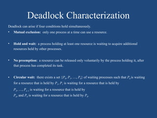
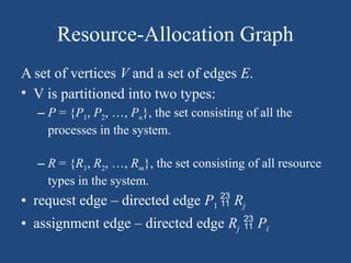
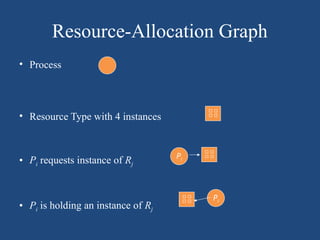
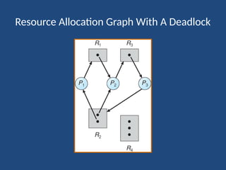
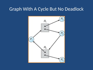
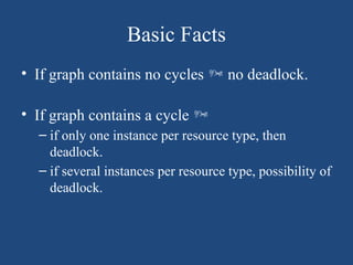
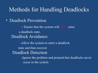
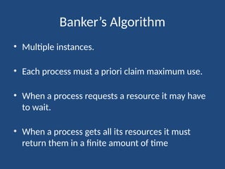
The document elaborates on deadlock in operating systems, detailing its characterization, methods for handling, prevention, avoidance, and detection. It describes a deadlock as a scenario where a set of blocked processes await resources held by each other and outlines the necessary conditions for its occurrence. Additionally, it explains the resource-allocation graph and presents the Banker's algorithm for resource allocation and safe states amidst potential deadlocks.

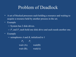
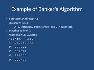
![Steps for Banker’s Algorithm
Let n = number of processes, and m = number of resources types.
• Available: Vector of length m. If available [j] = k, there are k
instances of resource type Rj available.
• Max: n x m matrix. If Max [i,j] = k, then process Pi may request
at most k instances of resource type Rj.
• Allocation: n x m matrix. If Allocation[i,j] = k then Pi is currently
allocated k instances of Rj.
• Need: n x m matrix. If Need[i,j] = k, then Pi may need k more
instances of Rj to complete its task.
Need [i,j] = Max[i,j] – Allocation [i,j].](https://image.slidesharecdn.com/deadlock-241217070106-43f25673/85/Deadlock-in-Operating-SystemSystem-Model-Deadlock-Characterization-19-320.jpg)
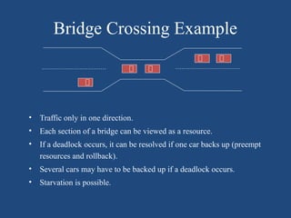
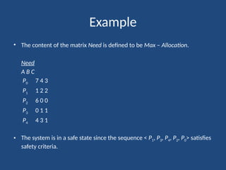
![Resource-Request Algorithm for Process Pi
Request = request vector for process Pi. If Requesti [j] = k then
process Pi wants k instances of resource type Rj.
1. If Requesti Needi go to step 2. Otherwise, raise error condition,
since process has exceeded its maximum claim.
2. If Requesti Available, go to step 3. Otherwise Pi must wait, since
resources are not available.
3. Pretend to allocate requested resources to Pi by modifying the
state as follows:
Available = Available – Request;
Allocationi = Allocationi + Requesti;
Needi = Needi – Requesti;
If safe the resources are allocated to Pi.
If unsafe Pi must wait, and the old resource-allocation state is restored](https://image.slidesharecdn.com/deadlock-241217070106-43f25673/85/Deadlock-in-Operating-SystemSystem-Model-Deadlock-Characterization-20-320.jpg)


![OpenGL Mini Projects With Source Code [ Computer Graphics ]](https://cdn.slidesharecdn.com/ss_thumbnails/newmicrosoftpowerpointpresentation-180330204024-thumbnail.jpg?width=640&height=640&fit=bounds)