Download as PDF, PPTX


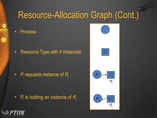


![Data Structures for the Banker’s Algorithm
Let n = number of processes, and m = number of
resources types.
• Available: Vector of length m. If available [j] = k, there are k instances of
resource type Rj available
• Max: n x m matrix. If Max [i,j] = k, then process Pi may request at most k
instances of resource type Rj
• Allocation: n x m matrix. If Allocation[i,j] = k then Pi is currently allocated k
instances of Rj
• Need: n x m matrix. If Need[i,j] = k, then Pi may need k more instances of Rj to
complete its task
Need [i,j] = Max[i,j] – Allocation [i,j]](https://image.slidesharecdn.com/ch7-deadlocks-140116113245-phpapp02/85/Ch7-deadlocks-26-320.jpg)
![Safety Algorithm
1. Let Work and Finish be vectors of length m and n, respectively.
Initialize:
Work = Available
Finish [i] = false for i = 0, 1, …, n- 1
2. Find an i such that both:
(a) Finish [i] = false
(b) Needi Work
If no such i exists, go to step 4
3. Work = Work + Allocationi
Finish[i] = true
go to step 2
4. If Finish [i] == true for all i, then the system is in a safe state](https://image.slidesharecdn.com/ch7-deadlocks-140116113245-phpapp02/85/Ch7-deadlocks-27-320.jpg)
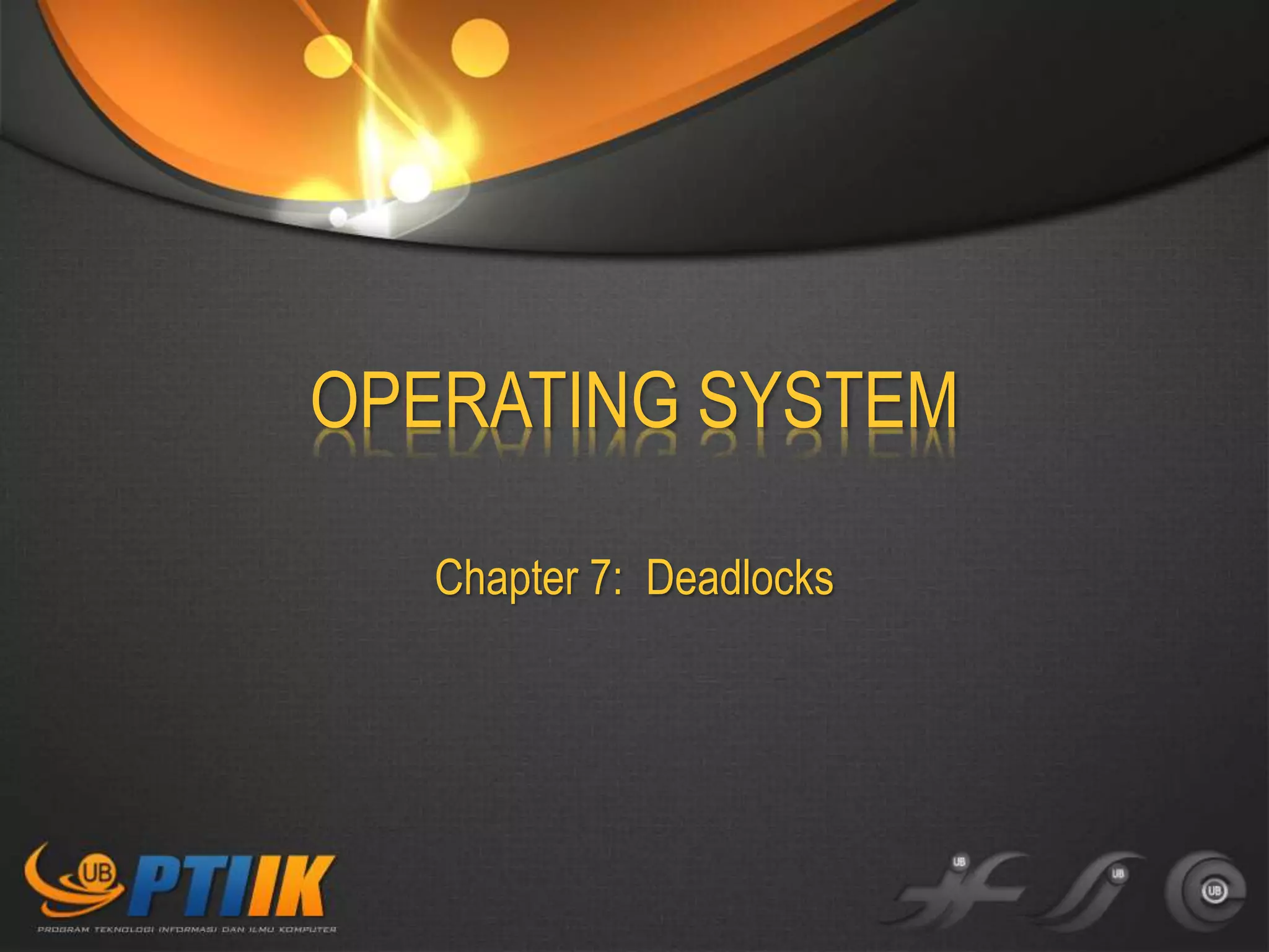
![Resource-Request Algorithm for Process Pi
Request = request vector for process Pi. If Requesti [j] = k
then process Pi wants k instances of resource type Rj
1. If Requesti Needi go to step 2. Otherwise, raise error condition, since
process has exceeded its maximum claim
2. If Requesti Available, go to step 3. Otherwise Pi must wait, since
resources are not available
3. Pretend to allocate requested resources to Pi by modifying the state as
follows:
Available = Available – Request;
Allocationi = Allocationi + Requesti;
Needi = Needi – Requesti;
If safe the resources are allocated to Pi
If unsafe Pi must wait, and the old resource-allocation state is restored](https://image.slidesharecdn.com/ch7-deadlocks-140116113245-phpapp02/85/Ch7-deadlocks-28-320.jpg)

![Several Instances of a Resource Type
• Available: A vector of length m indicates the number of
available resources of each type
• Allocation: An n x m matrix defines the number of
resources of each type currently allocated to each
process
• Request: An n x m matrix indicates the current request
of each process. If Request [i][j] = k, then process Pi is
requesting k more instances of resource type Rj.](https://image.slidesharecdn.com/ch7-deadlocks-140116113245-phpapp02/85/Ch7-deadlocks-35-320.jpg)
![Detection Algorithm
1. Let Work and Finish be vectors of length m and n, respectively
Initialize:
(a) Work = Available
(b) For i = 1,2, …, n, if Allocationi 0, then
Finish[i] = false; otherwise, Finish[i] = true
2. Find an index i such that both:
(a) Finish[i] == false
(b) Requesti Work
If no such i exists, go to step 4](https://image.slidesharecdn.com/ch7-deadlocks-140116113245-phpapp02/85/Ch7-deadlocks-36-320.jpg)
![Detection Algorithm (Cont.)
3. Work = Work + Allocationi
Finish[i] = true
go to step 2
4. If Finish[i] == false, for some i, 1 i n, then the system
is in deadlock state. Moreover, if Finish[i] == false, then
Pi is deadlocked
Algorithm requires an order of O(m x n2) operations to
detect whether the system is in deadlocked state](https://image.slidesharecdn.com/ch7-deadlocks-140116113245-phpapp02/85/Ch7-deadlocks-37-320.jpg)
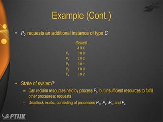
![Example of Detection Algorithm
• Five processes P0 through P4; three resource types
A (7 instances), B (2 instances), and C (6 instances)
• Snapshot at time T0:
Allocation
P0
P1
P2
P3
P4
Request
Available
ABC
010
200
303
211
002
ABC
000
202
000
100
002
ABC
000
• Sequence <P0, P2, P3, P1, P4> will result in Finish[i] = true for all i](https://image.slidesharecdn.com/ch7-deadlocks-140116113245-phpapp02/85/Ch7-deadlocks-38-320.jpg)


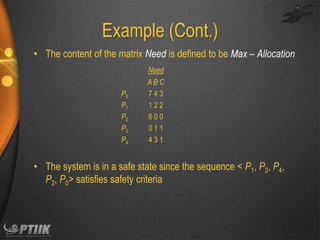
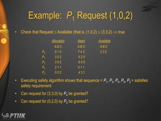
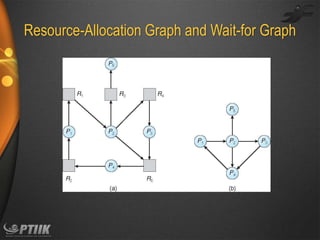
The document discusses deadlocks in operating systems. It defines deadlocks as a situation where a set of concurrent processes are prevented from completing tasks due to circular resource dependencies. The document outlines four conditions required for deadlock and presents methods for handling deadlocks, including prevention, avoidance, detection, and recovery. It provides examples using resource allocation graphs and the banker's algorithm to model processes and resources to ensure the system remains in a safe state to avoid deadlocks.


![Hci [4]interaction](https://cdn.slidesharecdn.com/ss_thumbnails/hci-4interaction-140116110608-phpapp01-thumbnail.jpg?width=640&height=640&fit=bounds)