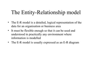
The Entity-Relationship model
•The E-R model is a detailed, logical representation of the
data for an organisation or business area
• It must be flexible enough so that it can be used and
understood in practically any environment where
information is modelled
• The E-R model is usually expressed as an E-R diagram
3.
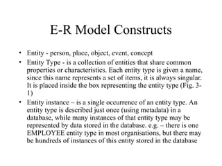
E-R Model Constructs
•Entity - person, place, object, event, concept
• Entity Type - is a collection of entities that share common
properties or characteristics. Each entity type is given a name,
since this name represents a set of items, it is always singular.
It is placed inside the box representing the entity type (Fig. 3-
1)
• Entity instance – is a single occurrence of an entity type. An
entity type is described just once (using metadata) in a
database, while many instances of that entity type may be
represented by data stored in the database. e.g. – there is one
EMPLOYEE entity type in most organisations, but there may
be hundreds of instances of this entity stored in the database
Entity type versussystem input,
output or user
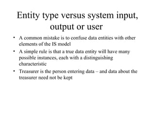
• A common mistake is to confuse data entities with other
elements of the IS model
• A simple rule is that a true data entity will have many
possible instances, each with a distinguishing
characteristic
• Treasurer is the person entering data – and data about the
treasurer need not be kept
6.
Entity type versussystem input,
output or user
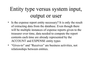
• Is the expense report entity necessary? It is only the result
of extracting data from the database. Even though there
will be multiple instances of expense reports given to the
treasurer over time, data needed to compute the report
contents each time are already represented by the
ACCOUNT and EXPENSE entity types
• “Gives-to” and “Receives” are business activities, not
relationships between entities.
7.
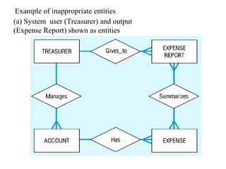
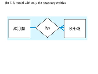
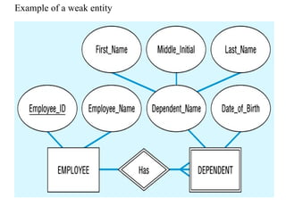
Example of inappropriateentities
(a) System user (Treasurer) and output
(Expense Report) shown as entities
Strong versus Weakentity type
Most of the basic entity types are classified as strong entity
types [Rectangle] – one that exists independently from
other entity types (such as EMPLOYEE)
Always have a unique characteristic (identifier) – an
attribute or combination of attributes that uniquely
distinguish each occurrence of that identity
A weak entity type [[Double Rectangle]] – existence
depends on some other entity type. It has no meaning in
the ER diagram without the entity on which it depends
(such as DEPENDENT)
The entity type on which the weak entity type depends is
called the Identifying owner (or owner for short).
10.
Strong versus Weakentity type
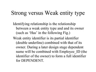
Identifying relationship is the relationship
between a weak entity type and and its owner
(such as ‘Has’ in the following Fig.)
Weak entity identifier is its partial identifier
(double underline) combined with that of its
owner. During a later design stage dependent
name will be combined with Employee_ID (the
identifier of the owner) to form a full identifier
for DEPENDENT.
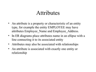
Attributes
• An attributeis a property or characteristic of an entity
type, for example the entity EMPLOYEE may have
attributes Employee_Name and Employee_Address.
• In ER diagrams place attributes name in an ellipse with a
line connecting it to its associated entity
• Attributes may also be associated with relationships
• An attribute is associated with exactly one entity or
relationship
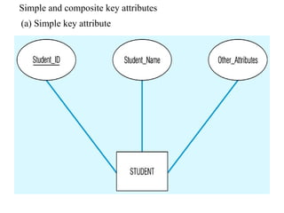
13.
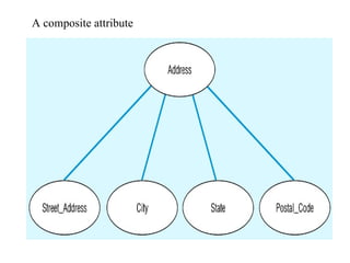
Simple versus composite
attributes(following Fig.)
• Some attributes can be broken down into meaningful
component parts, such as Address, which can be broken
down into Street_Address, City..etc.
• The component attributes may appear above or below the
composite attribute on an ER diagram
• Provide flexibility to users, as can refer to it as a single
unit or to the individual components
• A simple (atomic) attribute is one that cannot be broken
down into smaller components
Single-Valued versus
Multivalued Attribute
•It frequently happens that there is an attribute that may
have more than one value for a given instance, e.g.
EMPLOYEE may have more than one Skill.
• A multivalued attribute is one that may take on more than
one value – it is represented by an ellipse with double lines
16.
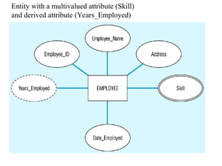
Entity with amultivalued attribute (Skill)
and derived attribute (Years_Employed)
17.
Stored versus DerivedAttributes
• Some attribute values can be calculated or derived from
others
• e.g., if Years_Employed needs to be calculated for
EMPLOYEE, it can be calculated using Date_Employed
and Today's_Date
• A derived attribute is one whose value can be calculated
from related attribute values (plus possibly other data not
in the database)
• A derived attribute is signified by an ellipse with a dashed
line (see previous Fig.)
18.
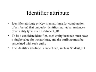
Identifier attribute
• Identifierattribute or Key is an attribute (or combination
of attributes) that uniquely identifies individual instances
of an entity type, such as Student_ID
• To be a candidate identifier, each entity instance must have
a single value for the attribute, and the attribute must be
associated with each entity
• The identifier attribute is underlined, such as Student_ID
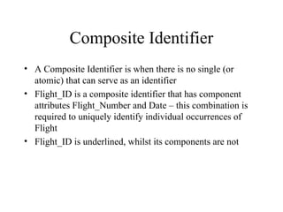
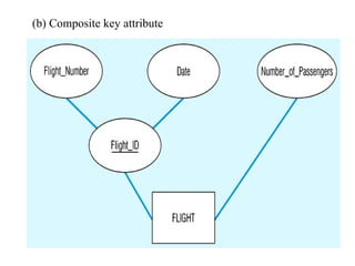
Composite Identifier
• AComposite Identifier is when there is no single (or
atomic) that can serve as an identifier
• Flight_ID is a composite identifier that has component
attributes Flight_Number and Date – this combination is
required to uniquely identify individual occurrences of
Flight
• Flight_ID is underlined, whilst its components are not
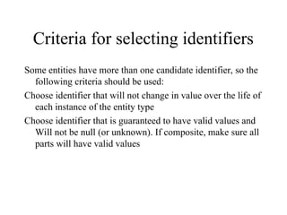
Criteria for selectingidentifiers
Some entities have more than one candidate identifier, so the
following criteria should be used:
Choose identifier that will not change in value over the life of
each instance of the entity type
Choose identifier that is guaranteed to have valid values and
Will not be null (or unknown). If composite, make sure all
parts will have valid values
23.
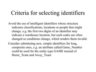
Criteria for selectingidentifiers
Avoid the use of intelligent identifiers whose structure
indicates classifications, locations or people that might
change. e.g. the first two digits of an identifier may
indicate a warehouse location, but such codes are often
changed as conditions change, which renders them invalid.
Consider substituting new, simple identifiers for long,
composite ones, e.g. an attribute called Game_Number
could be used for the entity type GAME instead of
Home_Team and Away_Team
24.
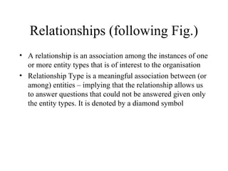
Relationships (following Fig.)
•A relationship is an association among the instances of one
or more entity types that is of interest to the organisation
• Relationship Type is a meaningful association between (or
among) entities – implying that the relationship allows us
to answer questions that could not be answered given only
the entity types. It is denoted by a diamond symbol
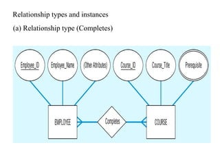
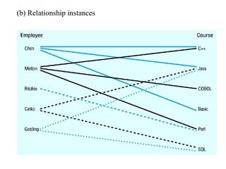
Relationship instance
• Isan association between (or among) entity instances,
where each relationship includes exactly one entity from
each participating entity type.
• For example, in the following figure each line represents a
relationship instance between one employee and one
course, indicating that the employee has completed that
course
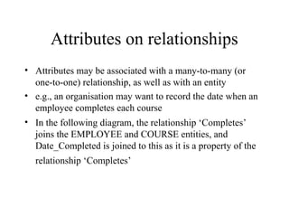
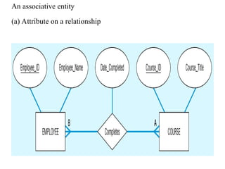
Attributes on relationships
•Attributes may be associated with a many-to-many (or
one-to-one) relationship, as well as with an entity
• e.g., an organisation may want to record the date when an
employee completes each course
• In the following diagram, the relationship ‘Completes’
joins the EMPLOYEE and COURSE entities, and
Date_Completed is joined to this as it is a property of the
relationship ‘Completes’
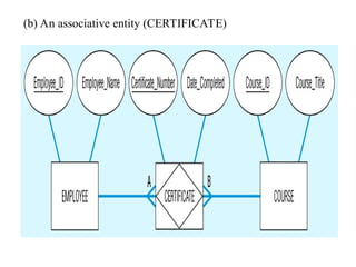
Associative entities
• Thepresence of one or more attributes on a relationship
suggests that the relationship should perhaps be
represented as an entity type
• An associative entity is an entity type that associates the
instances of one or more entity types and contains
attributes that are peculiar to the relationship between
those entity instances.
• The associative entity type CERTIFICATE is represented
with the diamond relationship symbol enclosed within the
entity rectangle
31.
Associative entities
• Thepurpose of this special symbol is to preserve the
information that the entity was initially specified as a
relationship on the ER diagram
• There is no relationship diamond on the line between an
associative entity and a strong entity, because the
associative entity represents the relationship
32.
Associative entities
• Howdo you know when to convert a relationship to an
associative entity type? Four conditions should exist:
• All of the relationships are ‘many’ relationships
• The resulting associative identity type has independent
meaning to end-users, and can preferably be identified
with a single-attribute identifier
33.
Associative entities
• Theassociative entity has one or more attributes in
addition to the identifier
• The associative entity participates in one or more
relationships independent of the entities related in the
associated relationship
• The following figure shows the relationship ‘Completes’
converted to an associative entity type
• A CERTIFICATE is awarded to each EMPLOYEE who
completes a COURSE, each certificate has a
Certificate_Number that serves as the identifier
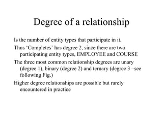
Degree of arelationship
Is the number of entity types that participate in it.
Thus ‘Completes’ has degree 2, since there are two
participating entity types, EMPLOYEE and COURSE
The three most common relationship degrees are unary
(degree 1), binary (degree 2) and ternary (degree 3 –see
following Fig.)
Higher degree relationships are possible but rarely
encountered in practice
36.
Unary relationship
• Isbetween the instances of a single entity type (also called
recursive relationships)
• ‘Is_Married_To’ is a one-to-one relationship between
instances of the PERSON entity type
• ‘Manages’ is a one-to-many relationship between instances
of the EMPLOYEE entity type
37.
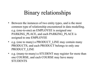
Binary relationships
• Betweenthe instances of two entity types, and is the most
common type of relationship encountered in data modelling.
e.g. (one-to-one) an EMPLOYEE is assigned one
PARKING_PLACE, and each PARKING_PLACE is
assigned to one EMPLOYEE
• e.g. (one to many) a PRODUCT_LINE may contain many
PRODUCTS, and each PRODUCT belongs to only one
PRODUCT_LINE
• e.g. (many-to-many) a STUDENT may register for more than
one COURSE, and each COURSE may have many
STUDENTS
38.
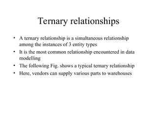
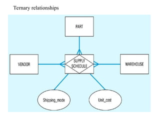
Ternary relationships
• Aternary relationship is a simultaneous relationship
among the instances of 3 entity types
• It is the most common relationship encountered in data
modelling
• The following Fig. shows a typical ternary relationship
• Here, vendors can supply various parts to warehouses
39.
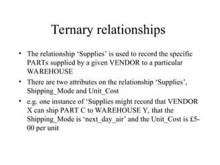
Ternary relationships
• Therelationship ‘Supplies’ is used to record the specific
PARTs supplied by a given VENDOR to a particular
WAREHOUSE
• There are two attributes on the relationship ‘Supplies’,
Shipping_Mode and Unit_Cost
• e.g. one instance of ‘Supplies might record that VENDOR
X can ship PART C to WAREHOUSE Y, that the
Shipping_Mode is ‘next_day_air’ and the Unit_Cost is £5-
00 per unit
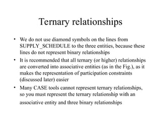
Ternary relationships
• Wedo not use diamond symbols on the lines from
SUPPLY_SCHEDULE to the three entities, because these
lines do not represent binary relationships
• It is recommended that all ternary (or higher) relationships
are converted into associative entities (as in the Fig.), as it
makes the representation of participation constraints
(discussed later) easier
• Many CASE tools cannot represent ternary relationships,
so you must represent the ternary relationship with an
associative entity and three binary relationships
42.
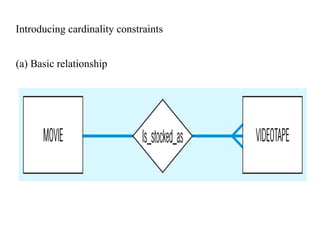
Cardinality constraints
• Thenumber of instances of one entity that can or must be
associated with each instance of another entity.
• If we have two entity types A and B, the cardinality
constraint specifies the number of instances of entity B
that can (or must) be associated with entity A
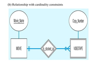
• e.g. a video store may stock more than one VIDEOTAPE
for each MOVIE, this is a ‘one-to-many’ relationship as in
the following Fig.
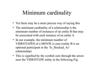
Minimum cardinality
• Yetthere may be a more precise way of saying this
• The minimum cardinality of a relationship is the
minimum number of instances of an entity B that may
be associated with each instance of an entity A
• In our example, the minimum number of
VIDEOTAPES of a MOVIE is zero (entity B is an
optional participant in the ‘Is_Stocked_As’
relationship)
• This is signified by the symbol zero through the arrow
near the VIDEOTAPE entity in the following Fig.
45.
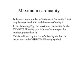
Maximum cardinality
• Isthe maximum number of instances of an entity B that
may be associated with each instance of entity A
• In the following Fig., the maximum cardinality for the
VIDEOTAPE entity type is ‘many’ (an unspecified
number greater than 1)
• This is indicated by the ‘crow’s foot’ symbol on the
arrow next to the VIDEOTAPE entity symbol
46.
Mandatory one cardinality
•Relationships are bi-directional, so there is also
cardinality notation next to the MOVIE entity
• Notice that as the minimum and maximum are both
one, this is called mandatory one cardinality (i.e., each
VIDEOTAPE of a MOVIE must be a copy of exactly
one movie)
• In the following Fig. Some attributes have been added.
VIDEOTAPE is represented as a weak entity because it
cannot exist unless the original owner movie also exists
47.
Mandatory one cardinality
•The identifier of the MOVIE is ‘Movie_Name’
• VIDEOTAPE does not have a unique identifier,
however the partial identifier Copy_Number together
with Movie_Name would uniquely identify an instance
of VIDEOTAPE
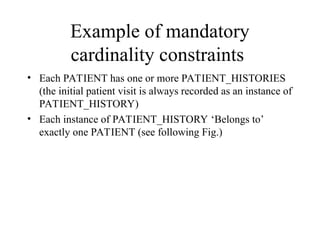
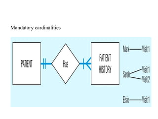
Example of mandatory
cardinalityconstraints
• Each PATIENT has one or more PATIENT_HISTORIES
(the initial patient visit is always recorded as an instance of
PATIENT_HISTORY)
• Each instance of PATIENT_HISTORY ‘Belongs to’
exactly one PATIENT (see following Fig.)
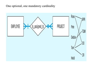
Example of oneoptional, one
mandatory cardinality constraint
• EMPLOYEE Is_Assigned_To PROJECT
• Each PROJECT has at least one EMPLOYEE assigned to
it (some projects have more than one)
• Each EMPLOYEE may or (optionally) may not be
assigned to any existing PROJECT, or may be assigned to
one or more PROJECTs (see following Fig.)
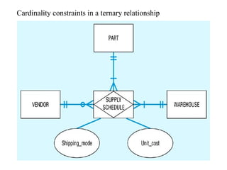
An example usinga ternary
relationship
• PART and WAREHOUSE are mandatory participants in
the relationship, whilst VENDOR is an optional participant
• The cardinality of each of the participating entities is
mandatory one, since each SUPPLY_SCHEDULE
instance must be related to exactly one instance of each of
these participating entity types
54.
An example usinga ternary
relationship
• Each VENDOR can supply many PARTs to any number of
WAREHOUSES, but need not supply any parts
• Each PART can be supplied by any number of VENDORs
to more than one WAREHOUSE, but each part must be
supplied by at least one vendor to a warehouse
• Each WAREHOUSE can be supplied with any number of
PARTS from more than one VENDOR, but each
warehouse must be supplied with at least one part
An example usinga ternary
relationship
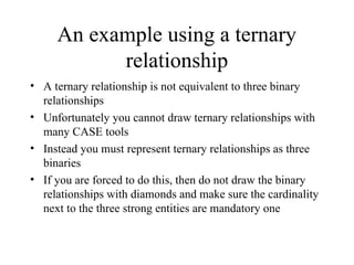
• A ternary relationship is not equivalent to three binary
relationships
• Unfortunately you cannot draw ternary relationships with
many CASE tools
• Instead you must represent ternary relationships as three
binaries
• If you are forced to do this, then do not draw the binary
relationships with diamonds and make sure the cardinality
next to the three strong entities are mandatory one
57.
Modelling time-dependent data
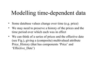
•Some database values change over time (e.g. price)
• We may need to preserve a history of the prices and the
time period over which each was in effect
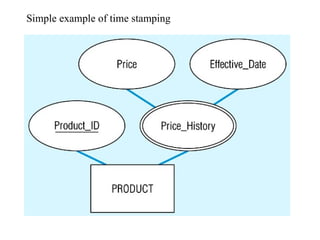
• We can think of a series of prices and the effective date
(see Fig.), giving a (composite) multivalued attribute
Price_History (that has components ‘Price’ and
‘Effective_Date’)
Time stamps
• Aresimply time values associated with a data value
• May be recorded to indicate the time the value was entered
(transaction time), time the value becomes valid or stops
being valid, or the time when critical actions were
performed (such as updates, corrections or audits)
60.
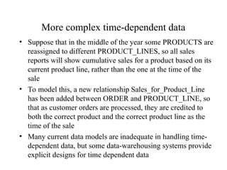
More complex time-dependentdata
• Suppose that in the middle of the year some PRODUCTS are
reassigned to different PRODUCT_LINES, so all sales
reports will show cumulative sales for a product based on its
current product line, rather than the one at the time of the
sale
• To model this, a new relationship Sales_for_Product_Line
has been added between ORDER and PRODUCT_LINE, so
that as customer orders are processed, they are credited to
both the correct product and the correct product line as the
time of the sale
• Many current data models are inadequate in handling time-
dependent data, but some data-warehousing systems provide
explicit designs for time dependent data
62.
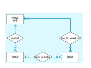
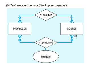
Multiple relationships
• Insome situations an organisation may want to model more
than one relationship between the same entity types
• The following figure shows two relationships between
PROFESSOR and COURSE
• The relationship Is_Qualified associates professors with the
courses they are qualified to teach
• A given course may have more than one person qualified to
teach it, or (optionally) may not have any qualified instructors
(such as a new course)
• Each professor should be qualified to teach at least one course
(we hope!)
63.
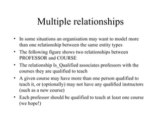
Multiple relationships
• Thesecond relationship in this figure associates professors
with the courses they actually teach during a given
semester (where the maximum cardinality for a given
semester is 4)
• This shows how a fixed constraint (upper or lower) can be
recorded
• The attribute ‘Semester’ (which could be a composite
attribute with components ‘Semester_Name’ and ‘Year’) is
on the relationship Is_Scheduled)
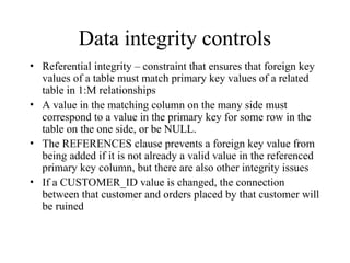
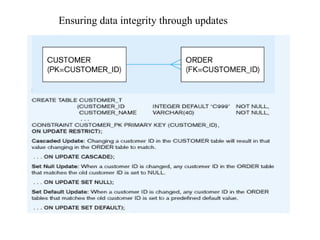
Data integrity controls
•Referential integrity – constraint that ensures that foreign key
values of a table must match primary key values of a related
table in 1:M relationships
• A value in the matching column on the many side must
correspond to a value in the primary key for some row in the
table on the one side, or be NULL.
• The REFERENCES clause prevents a foreign key value from
being added if it is not already a valid value in the referenced
primary key column, but there are also other integrity issues
• If a CUSTOMER_ID value is changed, the connection
between that customer and orders placed by that customer will
be ruined
67.
Data integrity controls
•The REFERENCES clause prevents making such a key in
the foreign value, but not in the primary key value
• Can be handled by asserting that the primary key values
cannot be changed once they are established. In this case,
updates to the customer table will be handled by including
an ON UPDATE RESTRICT clause - so any updates to a
primary key value will be rejected unless no foreign key
references that value in any child table (see Fig.)
• Another solution is to pass the changes through to the child
tables by using ON UPDATE CASCADE
68.
Data integrity controls
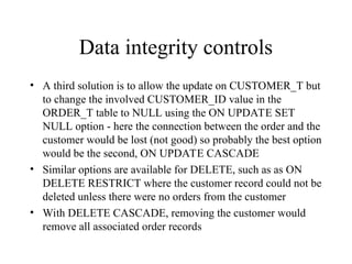
•A third solution is to allow the update on CUSTOMER_T but
to change the involved CUSTOMER_ID value in the
ORDER_T table to NULL using the ON UPDATE SET
NULL option - here the connection between the order and the
customer would be lost (not good) so probably the best option
would be the second, ON UPDATE CASCADE
• Similar options are available for DELETE, such as as ON
DELETE RESTRICT where the customer record could not be
deleted unless there were no orders from the customer
• With DELETE CASCADE, removing the customer would
remove all associated order records
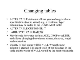
Changing tables
• ALTERTABLE statement allows you to change column
specifications (not in views). e.g. a ‘customer type’
column may be added to the CUSTOMER table:
• ALTER TABLE CUSTOMER_T
• ADD (TYPE VARCHAR(2))
• May include keywords such as ADD, DROP or ALTER
and allows changing the columns names, datatype, length
and constraints
• Usually its null status will be NULL.When the new
column is created, it is added to all of the instances in the
table and the value of NULL would be the most reasonable
71.
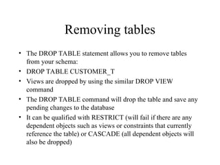
Removing tables
• TheDROP TABLE statement allows you to remove tables
from your schema:
• DROP TABLE CUSTOMER_T
• Views are dropped by using the similar DROP VIEW
command
• The DROP TABLE command will drop the table and save any
pending changes to the database
• It can be qualified with RESTRICT (will fail if there are any
dependent objects such as views or constraints that currently
reference the table) or CASCADE (all dependent objects will
also be dropped)
72.
Removing tables
• Canretain the tables structure but remove
all the data in the table using the
TRUNCATE_TABLE command.
73.
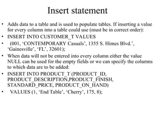
Insert statement
• Addsdata to a table and is used to populate tables. If inserting a value
for every column into a table could use (must be in correct order):
• INSERT INTO CUSTOMER_T VALUES
• (001, ‘CONTEMPORARY Casuals’, 1355 S. Himes Blvd.’,
‘Gainesville’, ‘FL’, 32601);
• When data will not be entered into every column either the value
NULL can be used for the empty fields or we can specify the columns
to which data are to be added:
• INSERT INTO PRODUCT_T (PRODUCT_ID,
PRODUCT_DESCRIPTION,PRODUCT_FINISH,
STANDARD_PRICE, PRODUCT_ON_HAND)
• VALUES (1, ‘End Table’, ‘Cherry’, 175, 8);
74.
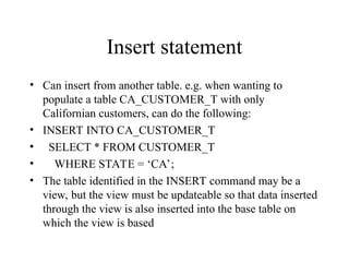
Insert statement
• Caninsert from another table. e.g. when wanting to
populate a table CA_CUSTOMER_T with only
Californian customers, can do the following:
• INSERT INTO CA_CUSTOMER_T
• SELECT * FROM CUSTOMER_T
• WHERE STATE = ‘CA’;
• The table identified in the INSERT command may be a
view, but the view must be updateable so that data inserted
through the view is also inserted into the base table on
which the view is based
75.
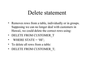
Delete statement
• Removesrows from a table, individually or in groups.
Supposing we can no longer deal with customers in
Hawaii, we could delete the correct rows using:
• DELETE FROM CUSTOMER_T
• WHERE STATE = ‘HI’;
• To delete all rows from a table:
• DELETE FROM CUSTOMER_T;
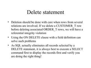
76.
Delete statement
• Deletionshould be done with care when rows from several
relations are involved. If we delete a CUSTOMER_T row
before deleting associated ORDER_T rows, we will have a
referential integrity violation
• Using the ON DELETE clause with a field definition can
solve such problems
• As SQL actually eliminates all records selected by a
DELETE statement, it is always best to execute a SELECT
command first to display the records first and verify you
are doing the right thing!
77.
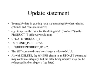
Update statement
• Tomodify data in existing rows we must specify what relation,
columns and rows are involved
• e.g., to update the price for the dining table (Product 7) in the
PRODUCT_T table we would use:
• UPDATE PRODUCT_T
• SET UNIT_PRICE = 775
• WHERE PRODUCT_ID = 7;
• The SET command can also change a value to NULL
• As with DELETE, the WHERE clause in an UPDATE command
may contain a subquery, but the table being updated may not be
referenced in the subquery (see later)
78.
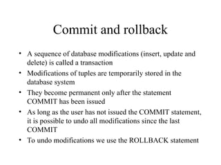
Commit and rollback
•A sequence of database modifications (insert, update and
delete) is called a transaction
• Modifications of tuples are temporarily stored in the
database system
• They become permanent only after the statement
COMMIT has been issued
• As long as the user has not issued the COMMIT statement,
it is possible to undo all modifications since the last
COMMIT
• To undo modifications we use the ROLLBACK statement
79.
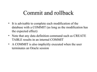
Commit and rollback
•It is advisable to complete each modification of the
database with a COMMIT (as long as the modification has
the expected effect)
• Note that any data definition command such as CREATE
TABLE results in an internal COMMIT
• A COMMIT is also implicitly executed when the user
terminates an Oracle session

![Strong versus Weak entity type
Most of the basic entity types are classified as strong entity
types [Rectangle] – one that exists independently from
other entity types (such as EMPLOYEE)
Always have a unique characteristic (identifier) – an
attribute or combination of attributes that uniquely
distinguish each occurrence of that identity
A weak entity type [[Double Rectangle]] – existence
depends on some other entity type. It has no meaning in
the ER diagram without the entity on which it depends
(such as DEPENDENT)
The entity type on which the weak entity type depends is
called the Identifying owner (or owner for short).](https://image.slidesharecdn.com/ch4erd-250916081403-f21fd399/85/ER-Modeling-in-implementation-with-conceptual-data-model-9-320.jpg)


![Polymer [ बहुलक ] Chemistry Notes PDF - Irfanullah Mehar - JJ Sir Chemistry.pdf](https://cdn.slidesharecdn.com/ss_thumbnails/polymerchemistrynotespdf-irfanullahmehar-jjsirchemistry-260210172118-3f9b37f7-thumbnail.jpg?width=640&height=640&fit=bounds)


