Downloaded 259 times


![Reliability
4. Applications Considered on Reliability
The word reliablity is an abstract term which refers to the degree to
which equipment or components, such as semiconductor devices, are
resistant to failure. Reliability can be and is often measured quantitatively.
Reliability is defined as “whether equipment or components (such as
a semiconductor device) under given conditions perform the same at
the end of a given period as at the beginning.”
2. Reliability Function
Collector Current Ic(A)
Failure Rate (λ)
us
SOA(Safe Operating Area)
Collector-Emitter Voltage Vce(V)
Figure 2 SOA
Initial
Failure
Random or
Chance Failure
Wear-out
Failure
Time (t)
Figure 1 Bath Tub Curve
These three types of failure describe “bathtub curve” shown in
Figure 1. Infant failures can be attributed to trouble in the production
process and can be eliminated by aging befor shipment to customers,
stricter control of the production process and quality control measures.
Semiconductor devices such as transistors, unlike electronic equipment,
take a considerable amount of time to reach the stage where wear-out
failure begins to occur. And, as shown in Figure 1 (b), they also last
much longer than electronic equipment. This shows that the longer they
are used the more stable they actually become.
The reduction that occurs in random failures can be approximated by
Weibull distribution, logarithmic normal distribution, or gamma distribution, but Weibull distribution best expresses the phenomenon that
occurs with transistors.
3. Quantitative Expression of Reliability
While there are many ways to quantitatively express reliability, two
criteria, failure rate and life span, are generally used to define the
reliability of semiconductors such as transistrors.
a) Failure Rate (FR)
Failure rate often refers to instantaneous failures or λ (t). In general
of reliability theory, however, the cumulative failure rate, or Reliability Index, is
r(t)
⋅⋅⋅⋅⋅⋅⋅⋅⋅⋅⋅⋅⋅⋅⋅⋅⋅⋅⋅⋅⋅⋅⋅⋅⋅⋅⋅⋅⋅⋅⋅⋅⋅⋅⋅⋅⋅⋅⋅⋅⋅⋅⋅⋅⋅⋅⋅⋅⋅⋅⋅⋅⋅⋅⋅⋅⋅⋅⋅⋅⋅⋅⋅⋅⋅⋅⋅⋅⋅⋅⋅⋅⋅⋅⋅⋅⋅⋅⋅⋅⋅⋅⋅(1)
N⋅t
Where N = Net quantity used, and
r(t) = Net quantitiy failed after t hours
If we assign t the arbitrary
F⋅R=
F ⋅ R = r × 100 (%/1,000 hours)⋅⋅⋅⋅⋅⋅⋅⋅⋅⋅⋅⋅⋅⋅⋅⋅⋅⋅⋅⋅⋅⋅⋅⋅⋅⋅⋅⋅⋅⋅⋅⋅⋅⋅⋅⋅⋅⋅⋅⋅⋅⋅⋅⋅⋅⋅⋅(2)
N
In situations where the cumulative failure rate is small, failure is expressed in units of one Fit, 10-9 (failures/hours).
b) Life Span(L)
Life Span can be expressed in terms of average lifespan or as Mean
Time Between Failure (MTBF), but assuming that random failure
is shown by the Index Distribution [λ (t) = constant], then Life Span
or L can be shown by the equation
1
L = ⋅ (hours)⋅⋅⋅⋅⋅⋅⋅⋅⋅⋅⋅⋅⋅⋅⋅⋅⋅⋅⋅⋅⋅⋅⋅⋅⋅⋅⋅⋅⋅⋅⋅⋅⋅⋅⋅⋅⋅⋅⋅⋅⋅⋅⋅⋅⋅⋅⋅⋅⋅⋅⋅⋅⋅⋅⋅⋅⋅⋅⋅⋅⋅⋅⋅⋅⋅⋅⋅⋅⋅⋅⋅⋅⋅⋅⋅⋅(3)
F R
6
Loc
Estimation
wn
Semiconductor
Devices
o
akd
Bre
ary wer
Po
bl e
wa
(b)
ond
llo
xA
General Electronic
Equipment or
Components
(a)
S ec
1. Infant failure
2. Random failure
3. Wear-out failure
Ma
In general, there are three types of failure modes in electronic components:
a) The type and specifications of our transistors and semiconductor
devices vary depending on the application that will be required by
their intended use. Customer should, therefore, determine
which type will best suit their purposes.
b) Note that high temperratures or long soldering periods must be avoided during soldering, as heat can be transmitted through external
leads into the interior. This may cause deterioration if the maximum
allowable temperature is exceeded.
c) When using the trasistor
under pulse operation or
Max.Allowable
inductive load, the Safe
Current
Operating Area (SOA) for
the current and voltage must
not be exceeded (Figure 2).
Max.
Allowable
Voltage Vceo(Max)
1. Definition of Reliability
d) The reliability of transistors and semiconductor devices is greatly
affected by the stress of junction temperature. If we accept in general
proceed in the form of Arrhenius equation, the relationship between
the junction temperature Tj and lifespan L can be expressed with
the following empirical formula
n L = A+ B ⋅⋅⋅⋅⋅⋅⋅⋅⋅⋅⋅⋅⋅⋅⋅⋅⋅⋅⋅⋅⋅⋅⋅⋅⋅⋅⋅⋅⋅⋅⋅⋅⋅⋅⋅⋅⋅⋅⋅⋅⋅⋅⋅⋅⋅⋅⋅⋅⋅⋅⋅⋅⋅⋅⋅⋅⋅⋅⋅⋅⋅⋅⋅⋅⋅⋅⋅⋅⋅⋅⋅⋅⋅⋅⋅⋅⋅⋅(4)
Tj
It is, hence, very important to derate the junction temperature to
assure a high reliability rate.
5. Reliability Test
Sanken bases its test methods and conditions on the following
standards. Tests are conducted under these or stricter conditions,
The details of these are shown in Table 1.
• MIL-STD-202F (Test method for electrical and electronic components)
• MIL-STD-750C (Test method for semiconductor equipment)
• JIS C 7021 (Endurance test and environmental test method for
individual semiconductor devices)
• JIS C 7022 (Endurance test and environmental test method for
integrated circuits of semiconductors)
6. Quality Assurance
To ensure high quality and high reliability, quality control and production process control procedures are executed from the receipt of parts
through the entire production process. Our quality assurance system
is shown in Figure 3.](https://image.slidesharecdn.com/datasheetpowertransistorssanken-131218234353-phpapp01/85/Data-sheet-power-transistors-sanken-8-320.jpg)


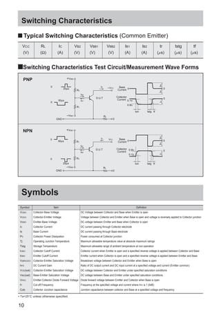


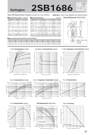


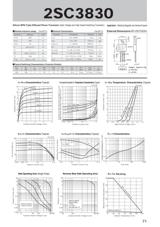


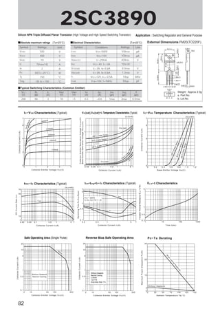


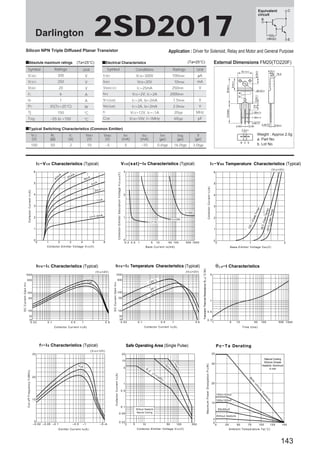


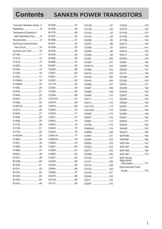
This document is a bulletin from Sanken Electric Co., Ltd. that provides information on their power transistors. It includes a transistor selection guide with charts showing electrical characteristics of various transistor models. It also provides details on individual transistor part numbers, specifications, and applications. The document cautions users to verify the latest information and obtain consent for intended applications of the transistors.