This document provides specifications for the 2SK3484 N-channel MOS field effect transistor (MOSFET) including:
- Electrical characteristics such as on-state resistance, gate cut-off voltage, and input/output capacitances.
- Thermal characteristics such as thermal resistance and power dissipation derating curves.
- Switching characteristics such as turn-on/off delay times and rise/fall times.
- Package drawings and equivalent circuit diagram for the TO-251 and TO-252 packages.
Original N Channel Mosfet 2SK3566 K3566 3566 2.5A 900V TO-220 NewAUTHELECTRONIC
Original N Channel Mosfet 2SK3566 K3566 3566 2.5A 900V TO-220 New
https://authelectronic.com/original-n-channel-mosfet-2sk3566-k3566-3566-2-5a-900v-to-220-new
Original N Channel Mosfet 2SK3566 K3566 3566 2.5A 900V TO-220 NewAUTHELECTRONIC
Original N Channel Mosfet 2SK3566 K3566 3566 2.5A 900V TO-220 New
https://authelectronic.com/original-n-channel-mosfet-2sk3566-k3566-3566-2-5a-900v-to-220-new
Original P-Channel Mosfet NTD2955T4G 2955G 2955 60V 12A TO-252 New On Semico...AUTHELECTRONIC
Original P-Channel Mosfet NTD2955T4G 2955G 2955 60V 12A TO-252 New On Semiconductor
https://authelectronic.com/original-p-channel-mosfet-ntd2955t4g-2955g-2955-60v-12a-to-252-new-on-semiconductor
Original N-Channel Mosfet DN2540 DN2540N5 2540 TO-220 New SupertexAUTHELECTRONIC
Original N-Channel Mosfet DN2540 DN2540N5 2540 TO-220 New Supertex
https://authelectronic.com/original-n-channel-mosfet-dn2540-dn2540n5-2540-to-220-new-supertex
Original N-channel 650 V 0.230 Ohm 12 A MDmesh V Power MOSFET in DPAK DPAK ST...AUTHELECTRONIC
Original N-channel 650 V 0.230 Ohm 12 A MDmesh V Power MOSFET in DPAK DPAK STF16N65M5 16N65M5 16N65 710V 12A TO-220FP New STMicroelectronics
https://authelectronic.com/original-n-channel-650-v-0-230-ohm-12-a-mdmesh-v-power-mosfet-in-dpak-dpak-stf16n65m5-16n65m5-16n65-710v-12a-to-220fp-new-stmicroelectronics
Original Power N-Channel MOSFET FR13N15D FR13N15 13N15 150V 14A TO-252 New In...AUTHELECTRONIC
Original Power N-Channel MOSFET FR13N15D FR13N15 13N15 150V 14A TO-252 New International Rectifier
https://authelectronic.com/original-power-n-channel-mosfet-fr13n15d-fr13n15-13n15-150v-14a-to-252-new-international-rectifier
Original N Channel Mosfet FQD10N60C STD10NM60N 10NM60 10N60 10A 600V TO-252 N...AUTHELECTRONIC
Original N Channel Mosfet FQD10N60C STD10NM60N 10NM60 10N60 10A 600V TO-252 New ST
https://authelectronic.com/original-n-channel-mosfet-fqd10n60c-std10nm60n-10nm60-10n60-10a-600v-to-252-new-st
Original Mosfet IRFB18N50KPBF IRFB18N50K FB18N50K 18N50K 500V 17A TO-220 New ...AUTHELECTRONIC
Original Mosfet IRFB18N50KPBF IRFB18N50K FB18N50K 18N50K 500V 17A TO-220 New International Rectifier
https://authelectronic.com/original-mosfet-irfb18n50kpbf-irfb18n50k-fb18n50k-18n50k-500v-17a-to-220-new-international-rectifier
Original Mosfet IRF4905PBF IRF4905 IRF4905 4905 55V 74A TO-220 New Internatio...AUTHELECTRONIC
Original Mosfet IRF4905PBF IRF4905 IRF4905 4905 55V 74A TO-220 New International Rectifier
https://authelectronic.com/original-mosfet-irf4905pbf-irf4905-irf4905-4905-55v-74a-to-220-new-international-rectifier
Original P Channel Mosfet IRF9Z34 IRF9Z34N IRF9Z34NPBF 9Z34 60V 18A TO 220 NewAUTHELECTRONIC
Original P Channel Mosfet IRF9Z34 IRF9Z34N IRF9Z34NPBF 9Z34 60V 18A TO 220 New
https://authelectronic.com/original-p-channel-mosfet-irf9z34-irf9z34n-irf9z34npbf-9z34-60v-18a-to-220-new
Original N Channel Mosfet T5A50D K5A50D 5A50D TO-220 5A 500V New Toshiba(Repl...AUTHELECTRONIC
Original N Channel Mosfet T5A50D K5A50D 5A50D TO-220 5A 500V New Toshiba(Replacement K10A60D)
https://authelectronic.com/original-n-channel-mosfet-t5a50d-k5a50d-5a50d-to-220-5a-500v-new-toshiba-replacement-k10a60d
Datasheet Layout for Semiconductor CompaniesAyça Little
Engineers have their own visual language which they use to communicate information about their products. Visual aids such as charts, graphs, tables, diagrams, mathematical symbols, detailed product blueprints and engineering drawings are all used to describe the product or application on offer.
It may seem like a cliché, but in many companies around the world, marketing and engineering departments often don't come into contact with each other and when they do they don’t always see eye to eye.
It is important for companies to come up with a system and workflow processes that allow for efficient communication and information sharing between these two departments so that products can be properly described and marketed. Effective use of technical documentation can lead to greater customer engagement and therefore more successful product sales and customer experiences.
Here is a “Semiconductor Datasheet Template “. TDSmaker offer you free Datasheet/ Specsheet/ Techsheet. Visit to ( https://www.tdsmaker.com ) to get start with free template.
Original P-CHANNEL MOSFET IRF5210PBF IRF5210 5210 100V 38A TO-220 New IRAUTHELECTRONIC
Original P-CHANNEL MOSFET IRF5210PBF IRF5210 5210 100V 38A TO-220 New IR
https://authelectronic.com/original-p-channel-mosfet-irf5210pbf-irf5210-5210-100v-38a-to-220-new-ir
Original N Channel Mosfet FQPF12N60 12N60 12A 600V New FairchildAUTHELECTRONIC
Original N Channel Mosfet FQPF12N60 12N60 12A 600V New Fairchild
https://authelectronic.com/original-n-channel-mosfet-fqpf12n60-12n60-12a-600v-new-fairchild
CFD Simulation of By-pass Flow in a HRSG module by R&R Consult.pptxR&R Consult
CFD analysis is incredibly effective at solving mysteries and improving the performance of complex systems!
Here's a great example: At a large natural gas-fired power plant, where they use waste heat to generate steam and energy, they were puzzled that their boiler wasn't producing as much steam as expected.
R&R and Tetra Engineering Group Inc. were asked to solve the issue with reduced steam production.
An inspection had shown that a significant amount of hot flue gas was bypassing the boiler tubes, where the heat was supposed to be transferred.
R&R Consult conducted a CFD analysis, which revealed that 6.3% of the flue gas was bypassing the boiler tubes without transferring heat. The analysis also showed that the flue gas was instead being directed along the sides of the boiler and between the modules that were supposed to capture the heat. This was the cause of the reduced performance.
Based on our results, Tetra Engineering installed covering plates to reduce the bypass flow. This improved the boiler's performance and increased electricity production.
It is always satisfying when we can help solve complex challenges like this. Do your systems also need a check-up or optimization? Give us a call!
Work done in cooperation with James Malloy and David Moelling from Tetra Engineering.
More examples of our work https://www.r-r-consult.dk/en/cases-en/
Immunizing Image Classifiers Against Localized Adversary Attacksgerogepatton
This paper addresses the vulnerability of deep learning models, particularly convolutional neural networks
(CNN)s, to adversarial attacks and presents a proactive training technique designed to counter them. We
introduce a novel volumization algorithm, which transforms 2D images into 3D volumetric representations.
When combined with 3D convolution and deep curriculum learning optimization (CLO), itsignificantly improves
the immunity of models against localized universal attacks by up to 40%. We evaluate our proposed approach
using contemporary CNN architectures and the modified Canadian Institute for Advanced Research (CIFAR-10
and CIFAR-100) and ImageNet Large Scale Visual Recognition Challenge (ILSVRC12) datasets, showcasing
accuracy improvements over previous techniques. The results indicate that the combination of the volumetric
input and curriculum learning holds significant promise for mitigating adversarial attacks without necessitating
adversary training.
About
Indigenized remote control interface card suitable for MAFI system CCR equipment. Compatible for IDM8000 CCR. Backplane mounted serial and TCP/Ethernet communication module for CCR remote access. IDM 8000 CCR remote control on serial and TCP protocol.
• Remote control: Parallel or serial interface.
• Compatible with MAFI CCR system.
• Compatible with IDM8000 CCR.
• Compatible with Backplane mount serial communication.
• Compatible with commercial and Defence aviation CCR system.
• Remote control system for accessing CCR and allied system over serial or TCP.
• Indigenized local Support/presence in India.
• Easy in configuration using DIP switches.
Technical Specifications
Indigenized remote control interface card suitable for MAFI system CCR equipment. Compatible for IDM8000 CCR. Backplane mounted serial and TCP/Ethernet communication module for CCR remote access. IDM 8000 CCR remote control on serial and TCP protocol.
Key Features
Indigenized remote control interface card suitable for MAFI system CCR equipment. Compatible for IDM8000 CCR. Backplane mounted serial and TCP/Ethernet communication module for CCR remote access. IDM 8000 CCR remote control on serial and TCP protocol.
• Remote control: Parallel or serial interface
• Compatible with MAFI CCR system
• Copatiable with IDM8000 CCR
• Compatible with Backplane mount serial communication.
• Compatible with commercial and Defence aviation CCR system.
• Remote control system for accessing CCR and allied system over serial or TCP.
• Indigenized local Support/presence in India.
Application
• Remote control: Parallel or serial interface.
• Compatible with MAFI CCR system.
• Compatible with IDM8000 CCR.
• Compatible with Backplane mount serial communication.
• Compatible with commercial and Defence aviation CCR system.
• Remote control system for accessing CCR and allied system over serial or TCP.
• Indigenized local Support/presence in India.
• Easy in configuration using DIP switches.
Sachpazis:Terzaghi Bearing Capacity Estimation in simple terms with Calculati...Dr.Costas Sachpazis
Terzaghi's soil bearing capacity theory, developed by Karl Terzaghi, is a fundamental principle in geotechnical engineering used to determine the bearing capacity of shallow foundations. This theory provides a method to calculate the ultimate bearing capacity of soil, which is the maximum load per unit area that the soil can support without undergoing shear failure. The Calculation HTML Code included.
Overview of the fundamental roles in Hydropower generation and the components involved in wider Electrical Engineering.
This paper presents the design and construction of hydroelectric dams from the hydrologist’s survey of the valley before construction, all aspects and involved disciplines, fluid dynamics, structural engineering, generation and mains frequency regulation to the very transmission of power through the network in the United Kingdom.
Author: Robbie Edward Sayers
Collaborators and co editors: Charlie Sims and Connor Healey.
(C) 2024 Robbie E. Sayers
Cosmetic shop management system project report.pdfKamal Acharya
Buying new cosmetic products is difficult. It can even be scary for those who have sensitive skin and are prone to skin trouble. The information needed to alleviate this problem is on the back of each product, but it's thought to interpret those ingredient lists unless you have a background in chemistry.
Instead of buying and hoping for the best, we can use data science to help us predict which products may be good fits for us. It includes various function programs to do the above mentioned tasks.
Data file handling has been effectively used in the program.
The automated cosmetic shop management system should deal with the automation of general workflow and administration process of the shop. The main processes of the system focus on customer's request where the system is able to search the most appropriate products and deliver it to the customers. It should help the employees to quickly identify the list of cosmetic product that have reached the minimum quantity and also keep a track of expired date for each cosmetic product. It should help the employees to find the rack number in which the product is placed.It is also Faster and more efficient way.
NO1 Uk best vashikaran specialist in delhi vashikaran baba near me online vas...Amil Baba Dawood bangali
Contact with Dawood Bhai Just call on +92322-6382012 and we'll help you. We'll solve all your problems within 12 to 24 hours and with 101% guarantee and with astrology systematic. If you want to take any personal or professional advice then also you can call us on +92322-6382012 , ONLINE LOVE PROBLEM & Other all types of Daily Life Problem's.Then CALL or WHATSAPP us on +92322-6382012 and Get all these problems solutions here by Amil Baba DAWOOD BANGALI
#vashikaranspecialist #astrologer #palmistry #amliyaat #taweez #manpasandshadi #horoscope #spiritual #lovelife #lovespell #marriagespell#aamilbabainpakistan #amilbabainkarachi #powerfullblackmagicspell #kalajadumantarspecialist #realamilbaba #AmilbabainPakistan #astrologerincanada #astrologerindubai #lovespellsmaster #kalajaduspecialist #lovespellsthatwork #aamilbabainlahore#blackmagicformarriage #aamilbaba #kalajadu #kalailam #taweez #wazifaexpert #jadumantar #vashikaranspecialist #astrologer #palmistry #amliyaat #taweez #manpasandshadi #horoscope #spiritual #lovelife #lovespell #marriagespell#aamilbabainpakistan #amilbabainkarachi #powerfullblackmagicspell #kalajadumantarspecialist #realamilbaba #AmilbabainPakistan #astrologerincanada #astrologerindubai #lovespellsmaster #kalajaduspecialist #lovespellsthatwork #aamilbabainlahore #blackmagicforlove #blackmagicformarriage #aamilbaba #kalajadu #kalailam #taweez #wazifaexpert #jadumantar #vashikaranspecialist #astrologer #palmistry #amliyaat #taweez #manpasandshadi #horoscope #spiritual #lovelife #lovespell #marriagespell#aamilbabainpakistan #amilbabainkarachi #powerfullblackmagicspell #kalajadumantarspecialist #realamilbaba #AmilbabainPakistan #astrologerincanada #astrologerindubai #lovespellsmaster #kalajaduspecialist #lovespellsthatwork #aamilbabainlahore #Amilbabainuk #amilbabainspain #amilbabaindubai #Amilbabainnorway #amilbabainkrachi #amilbabainlahore #amilbabaingujranwalan #amilbabainislamabad
Original N-Channel Mosfet 2SK3484 3484 16A 100V TO-252 New Renesas Electronics
1. The information in this document is subject to change without notice. Before using this document, please
confirm that this is the latest version.
Not all products and/or types are available in every country. Please check with an NEC Electronics
sales representative for availability and additional information.
MOS FIELD EFFECT TRANSISTOR
2SK3484
SWITCHING
N-CHANNEL POWER MOS FET
DATA SHEET
Document No. D15069EJ2V0DS00 (2nd edition)
Date Published August 2004 NS CP(K)
Printed in Japan
The mark shows major revised points.
2002
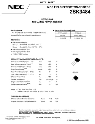
DESCRIPTION
The 2SK3484 is N-channel MOS Field Effect Transistor
designed for high current switching applications.
FEATURES
• Low on-state resistance
RDS(on)1 = 125 mΩ MAX. (VGS = 10 V, ID = 8 A)
RDS(on)2 = 148 mΩ MAX. (VGS = 4.5 V, ID = 8 A)
• Low Ciss: Ciss = 900 pF TYP.
• Built-in gate protection diode
• TO-251/TO-252 package
ABSOLUTE MAXIMUM RATINGS (TA = 25°C)
Drain to Source Voltage (VGS = 0 V) VDSS 100 V
Gate to Source Voltage (VDS = 0 V) VGSS ±20 V
Drain Current (DC) (TC = 25°C) ID(DC) ±16 A
Drain Current (pulse)
Note1
ID(pulse) ±22 A
Total Power Dissipation (TC = 25°C) PT1 30 W
Total Power Dissipation (TA = 25°C) PT2 1.0 W
Channel Temperature Tch 150 °C
Storage Temperature Tstg –55 to +150 °C
Single Avalanche Current
Note2
IAS 10 A
Single Avalanche Energy
Note2
EAS 10 mJ
Notes 1. PW ≤ 10 µs, Duty Cycle ≤ 1%
2. Starting Tch = 25°C, VDD = 50 V, RG = 25 Ω, VGS = 20 → 0 V
THERMAL RESISTANCE
Channel to Case Thermal Resistance Rth(ch-C) 4.17 °C/W
Channel to Ambient Thermal Resistance Rth(ch-A) 125 °C/W
(TO-251)
(TO-252)
ORDERING INFORMATION
PART NUMBER PACKAGE
2SK3484 TO-251 (MP-3)
2SK3484-Z TO-252 (MP-3Z)
www.DataSheet4U.com
2. Data Sheet D15069EJ2V0DS2
2SK3484
ELECTRICAL CHARACTERISTICS (TA = 25°C)
CHARACTERISTICS SYMBOL TEST CONDITIONS MIN. TYP. MAX. UNIT
Zero Gate Voltage Drain Current IDSS VDS = 100 V, VGS = 0 V 10 µA
Gate Leakage Current IGSS VGS = ±20 V, VDS = 0 V ±10 µA
Gate Cut-off Voltage VGS(off) VDS = 10 V, ID = 1 mA 1.5 2.0 2.5 V
Forward Transfer Admittance
Note
| yfs | VDS = 10 V, ID = 8 A 4.7 9.5 S
Drain to Source On-state Resistance
Note
RDS(on)1 VGS = 10 V, ID = 8 A 100 125 mΩ
RDS(on)2 VGS = 4.5 V, ID = 8 A 110 148 mΩ
Input Capacitance Ciss VDS = 10 V 900 pF
Output Capacitance Coss VGS = 0 V 110 pF
Reverse Transfer Capacitance Crss f = 1 MHz 50 pF
Turn-on Delay Time td(on) VDD = 50 V, ID = 8 A 9.0 ns
Rise Time tr VGS = 10 V 5.0 ns
Turn-off Delay Time td(off) RG = 0 Ω 30 ns
Fall Time tf 4.0 ns
Total Gate Charge QG VDD = 80 V 20 nC
Gate to Source Charge QGS VGS = 10 V 3.0 nC
Gate to Drain Charge QGD ID = 16 A 5.0 nC
Body Diode Forward Voltage
Note
VF(S-D) IF = 16 A, VGS = 0 V 1.0 V
Reverse Recovery Time trr IF = 16 A, VGS = 0 V 60 ns
Reverse Recovery Charge Qrr di/dt = 100 A/ µs 122 nC
Note Pulsed
TEST CIRCUIT 1 AVALANCHE CAPABILITY
RG = 25 Ω
50 Ω
PG.
L
VDD
VGS = 20 → 0 V
BVDSS
IAS
ID
VDS
Starting Tch
VDD
D.U.T.
TEST CIRCUIT 3 GATE CHARGE
TEST CIRCUIT 2 SWITCHING TIME
PG.
RG
0
VGS
D.U.T.
RL
VDD
τ = 1 sµ
Duty Cycle ≤ 1%
VGS
Wave Form
ID
Wave Form
VGS
10%
90%
VGS
10%0
ID
90%
90%
td(on) tr td(off) tf
10%
τ
ID
0
ton toff
PG. 50 Ω
D.U.T.
RL
VDD
IG = 2 mA
www.DataSheet4U.com
3. Data Sheet D15069EJ2V0DS 3
2SK3484
TYPICAL CHARACTERISTICS (TA = 25°C)
TC - Case Temperature - ˚C
PT-TotalPowerDissipation-W
0 8020 40 60 100 140120 160
TOTAL POWER DISSIPATION vs.
CASE TEMPERATURE
50
40
30
20
10
0
DERATING FACTOR OF FORWARD BIAS
SAFE OPERATING AREA
TC - Case Temperature - ˚C
dT-PercentageofRatedPower-%
0 4020 60 100 14080 120 160
120
100
80
60
40
20
PW - Pulse Width - s
TRANSIENT THERMAL RESISTANCE vs. PULSE WIDTH
rth(t)-TransientThermalResistance-˚C/W
10
0.01
0.1
1
100
1000
1 m 10 m 100 m 1 10 100 1000
Single Pulse
10 100
Rth(ch-C) = 4.17˚C/W
µ µ
Rth(ch-A) = 125˚C/W
FORWARD BIAS SAFE OPERATING AREA
VDS - Drain to Source Voltage - V
ID-DrainCurrent-A
10
1
0.1
100
0.1
1 10 100
TC = 25˚C
Single Pulse
1000
10
m
s
ID(pulse)
ID(DC)
1
m
s
100
µs10
µs
RDS(on)
Lim
ited
(atVG
S
=
10
V)
PowerDissipation
Lim
ited
DC
www.DataSheet4U.com
4. Data Sheet D15069EJ2V0DS4
2SK3484
DRAIN TO SOURCE ON-STATE
RESISTANCE vs. DRAIN CURRENT
ID - Drain Current - A
RDS(on)-DraintoSourceOn-stateResistance-mΩ
10.1
250
200
150
100
50
0
10 100
Pulsed
VGS = 4.5 V
10 V
GATE CUT-OFF VOLTAGE vs.
CHANNEL TEMPERATURE
Tch - Channel Temperature - ˚C
VGS(off)-GateCut-offVoltage-V
1
2
3
4
−50 0 50 100 150
0
VDS = 10 V
ID = 1 mA
FORWARD TRANSFER ADMITTANCE vs.
DRAIN CURRENT
ID - Drain Current - A
|yfs|-ForwardTransferAdmittance-S
0.01 0.1 1
10
100
10 100
0.1
0.01
1
Pulsed
TA = 150˚C
75˚C
25˚C
−40˚C
VDS = 10 V
DRAIN TO SOURCE ON-STATE RESISTANCE vs.
GATE TO SOURCE VOLTAGE
VGS - Gate to Source Voltage - V
RDS(on)-DraintoSourceOn-stateResistance-mΩ
5 10 15 20
200
150
100
50
0
8 A
ID = 16 A
Pulsed
DRAIN CURRENT vs.
DRAIN TO SOURCE VOLTAGE
VDS - Drain to Source Voltage - V
ID-DrainCurrent-A
2 3 410
VGS =10 V
4.5 V
25
20
15
10
5
0
Pulsed
FORWARD TRANSFER CHARACTERISTICS
VGS - Gate to Source Voltage - V
ID-DrainCurrent-A
1 2 3 4 5
1
0.01
10
1
0.1
100
TA = −40˚C
25˚C
75˚C
150˚C
Pulsed
VDS = 10 V
www.DataSheet4U.com
5. Data Sheet D15069EJ2V0DS 5
2SK3484
SWITCHING CHARACTERISTICS
ID - Drain Current - A
td(on),tr,td(off),tf-SwitchingTime-ns
10
1
10.1
100
1000
10 100
tf
tr
td(on)
td(off)
VDD = 50 V
VGS = 10 V
RG = 0 Ω
CAPACITANCE vs.
DRAIN TO SOURCE VOLTAGE
VDS - Drain to Source Voltage - V
Ciss,Coss,Crss-Capacitance-pF
10
0.01 0.1
100
1000
10000
1 10 100
Ciss
VGS = 0 V
f = 1 MHz
Coss
Crss
DRAIN TO SOURCE ON-STATE RESISTANCE vs.
CHANNEL TEMPERATURE
Tch - Channel Temperature - ˚C
RDS(on)-DraintoSourceOn-stateResistance-mΩ
−50 0 50 100 150
300
200
100
0
10 V
VGS = 4.5 V
ID = 8 A
Pulsed
SOURCE TO DRAIN DIODE
FORWARD VOLTAGE
1
ISD-DiodeForwardCurrent-A
0 1.5
VSD - Source to Drain Voltage - V
0.5
Pulsed
0.01
0.1
1
10
100
0 V
VGS = 10 V
REVERSE RECOVERY TIME vs.
DRAIN CURRENT
IF - Drain Current - A
trr-ReverseRecoveryTime-ns
di/dt = 100 A/ s
VGS = 0 V
1
0.1
10
1 10 100
1000
100
µ
DYNAMIC INPUT/OUTPUT CHARACTERISTICS VGS-GatetoDrainVoltage-V
QG - Gate Charge - nC
VDS-DraintoSourceVoltage-V
5 10 15 20 25
100
80
60
40
20
0
VDS
VGS
VDD = 80 V
50 V
20 V
ID = 16 A
10
8
6
4
2
0
www.DataSheet4U.com
6. Data Sheet D15069EJ2V0DS6
2SK3484
SINGLE AVALANCHE CURRENT vs.
INDUCTIVE LOAD
L - Inductive Load - mH
IAS-SingleAvalancheCurrent-A
1
10
100
1 10
VDD = 50V
RG = 25 Ω
VGS = 20→0 V
Startimg Tch = 25˚C
IAS = 10 A
0.01 0.1
0.1
EAS =10mJ
SINGLE AVALANCHE ENERGY
DERATING FACTOR
Starting Tch - Starting Channel Temperature - ˚C
EnergyDeratingFactor-%
25 50 75 100
160
140
120
100
80
60
40
20
0
125 150
VDD = 50 V
RG = 25 Ω
VGS = 20 → 0 V
IAS ≤ 10 A
www.DataSheet4U.com
7. Data Sheet D15069EJ2V0DS 7
2SK3484
PACKAGE DRAWINGS (Unit: mm)
1) TO-251 (MP-3) 2) TO-252 (MP-3Z)
1. Gate
2. Drain
3. Source
4. Fin (Drain)
21 3
6.5 ±0.2
5.0 ±0.2
4
1.5−0.1
+0.2
5.5±0.27.0MIN.
13.7MIN.
2.32.3
0.75
0.5 ±0.1
2.3 ±0.2
1.6±0.2
1.1 ±0.2
0.5 −0.1
+0.2
0.5 −0.1
+0.2
1. Gate
2. Drain
3. Source
4. Fin (Drain)
1 2 3
4
6.5 ±0.2
5.0 ±0.2
4.3MAX.0.8
2.3 2.3
0.9
MAX.
5.5±0.2
10.0MAX.
2.0
MIN.
1.5−0.1
+0.2
2.3 ±0.2
0.5 ±0.1
0.8
MAX.
0.8
1.0MIN.
1.8TYP.
0.7
1.1 ±0.2
EQUIVALENT CIRCUIT
Source
Body
Diode
Gate
Protection
Diode
Gate
Drain
Remark The diode connected between the gate and source of the transistor serves as a protector against ESD.
When this device actually used, an additional protection circuit is externally required if a voltage exceeding
the rated voltage may be applied to this device.
www.DataSheet4U.com
8. 2SK3484
The information in this document is current as of August, 2004. The information is subject to
change without notice. For actual design-in, refer to the latest publications of NEC Electronics data
sheets or data books, etc., for the most up-to-date specifications of NEC Electronics products. Not
all products and/or types are available in every country. Please check with an NEC Electronics sales
representative for availability and additional information.
No part of this document may be copied or reproduced in any form or by any means without the prior
written consent of NEC Electronics. NEC Electronics assumes no responsibility for any errors that may
appear in this document.
NEC Electronics does not assume any liability for infringement of patents, copyrights or other intellectual
property rights of third parties by or arising from the use of NEC Electronics products listed in this document
or any other liability arising from the use of such products. No license, express, implied or otherwise, is
granted under any patents, copyrights or other intellectual property rights of NEC Electronics or others.
Descriptions of circuits, software and other related information in this document are provided for illustrative
purposes in semiconductor product operation and application examples. The incorporation of these
circuits, software and information in the design of a customer's equipment shall be done under the full
responsibility of the customer. NEC Electronics assumes no responsibility for any losses incurred by
customers or third parties arising from the use of these circuits, software and information.
While NEC Electronics endeavors to enhance the quality, reliability and safety of NEC Electronics products,
customers agree and acknowledge that the possibility of defects thereof cannot be eliminated entirely. To
minimize risks of damage to property or injury (including death) to persons arising from defects in NEC
Electronics products, customers must incorporate sufficient safety measures in their design, such as
redundancy, fire-containment and anti-failure features.
NEC Electronics products are classified into the following three quality grades: "Standard", "Special" and
"Specific".
The "Specific" quality grade applies only to NEC Electronics products developed based on a customer-
designated "quality assurance program" for a specific application. The recommended applications of an NEC
Electronics product depend on its quality grade, as indicated below. Customers must check the quality grade of
each NEC Electronics product before using it in a particular application.
"Standard": Computers, office equipment, communications equipment, test and measurement equipment, audio
and visual equipment, home electronic appliances, machine tools, personal electronic equipment
and industrial robots.
"Special": Transportation equipment (automobiles, trains, ships, etc.), traffic control systems, anti-disaster
systems, anti-crime systems, safety equipment and medical equipment (not specifically designed
for life support).
"Specific": Aircraft, aerospace equipment, submersible repeaters, nuclear reactor control systems, life
support systems and medical equipment for life support, etc.
The quality grade of NEC Electronics products is "Standard" unless otherwise expressly specified in NEC
Electronics data sheets or data books, etc. If customers wish to use NEC Electronics products in applications
not intended by NEC Electronics, they must contact an NEC Electronics sales representative in advance to
determine NEC Electronics' willingness to support a given application.
(Note)
(1) "NEC Electronics" as used in this statement means NEC Electronics Corporation and also includes its
majority-owned subsidiaries.
(2) "NEC Electronics products" means any product developed or manufactured by or for NEC Electronics (as
defined above).
•
•
•
•
•
•
M8E 02. 11-1
www.DataSheet4U.com