Downloaded 443 times
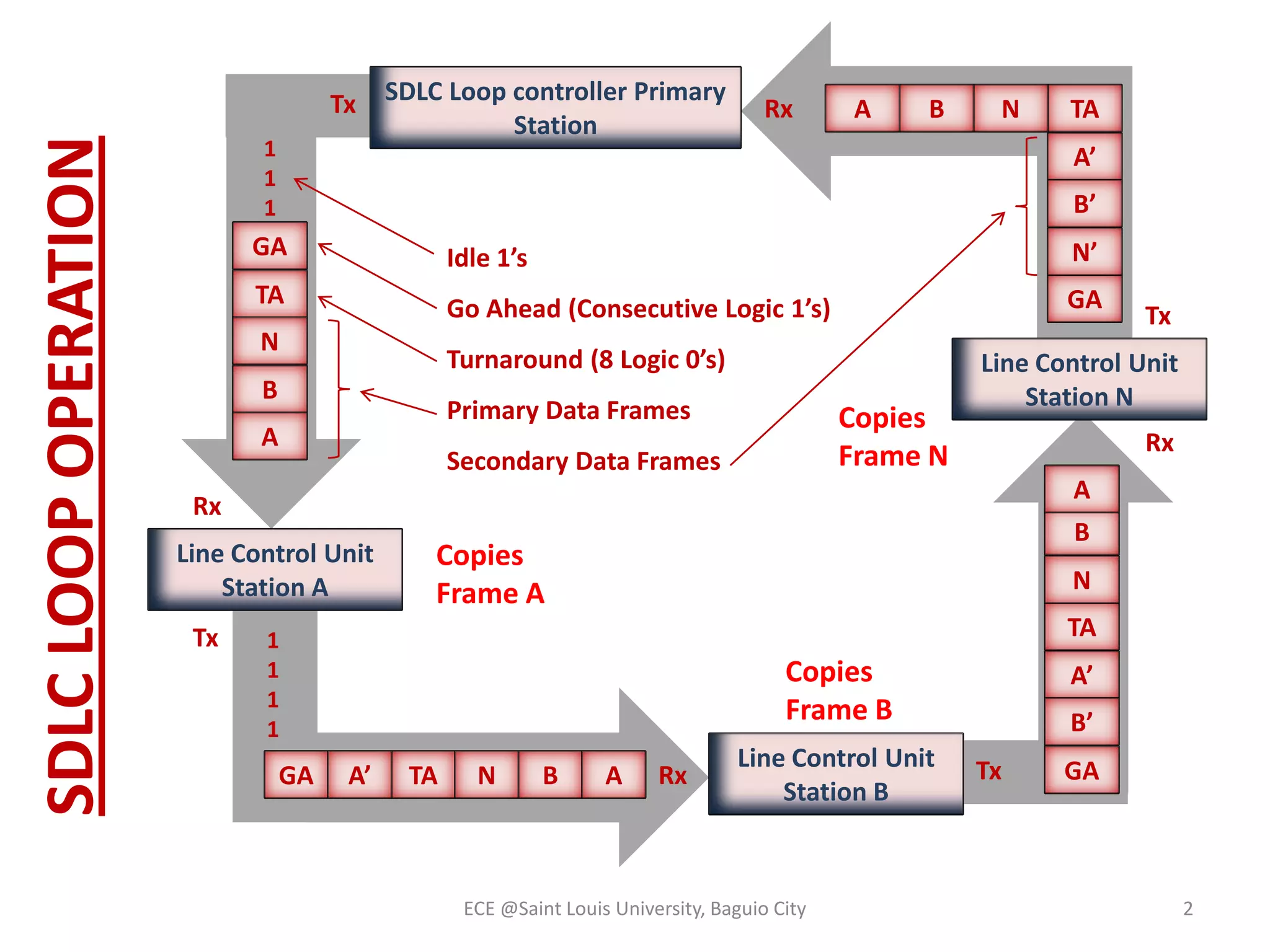
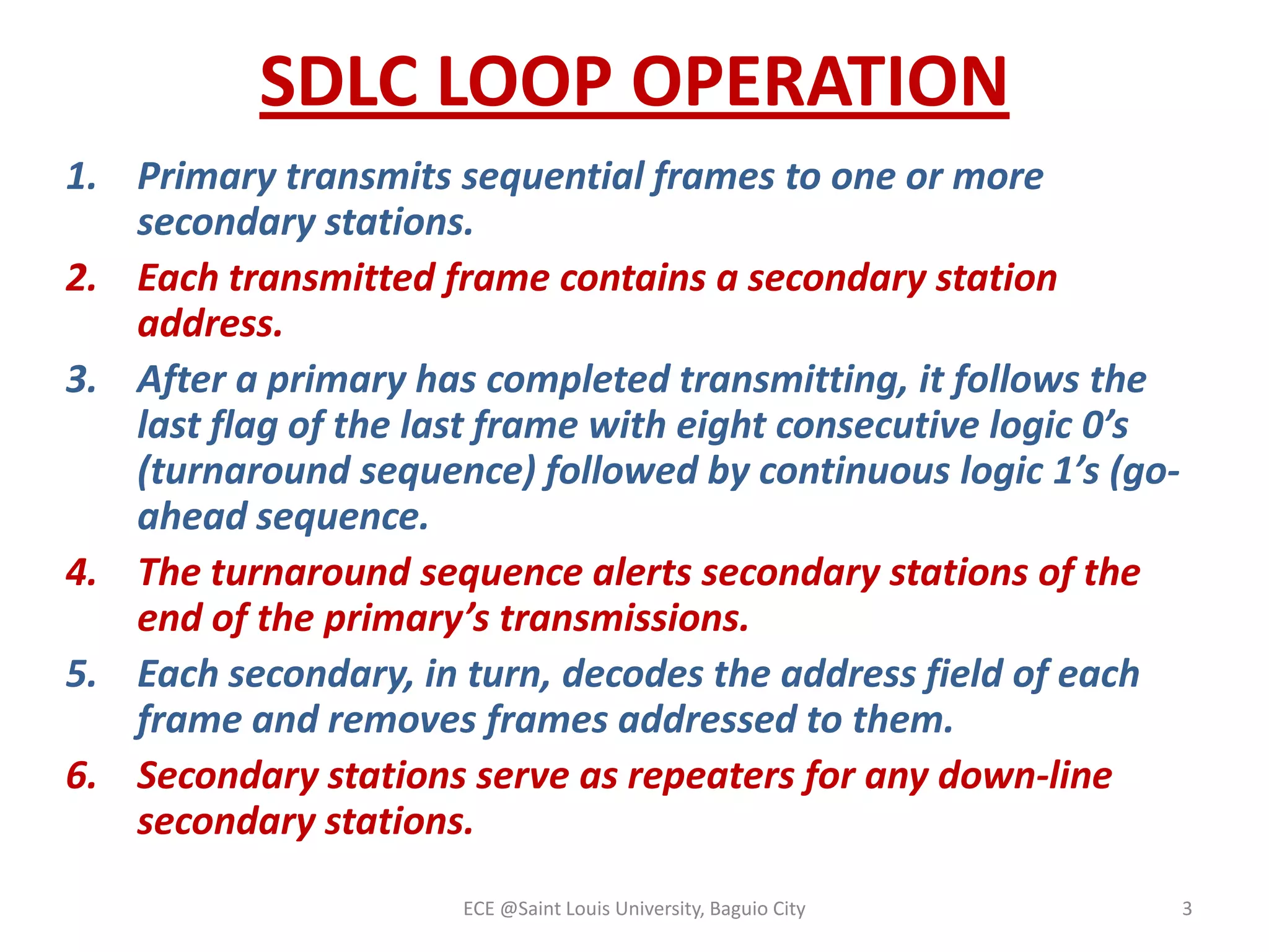
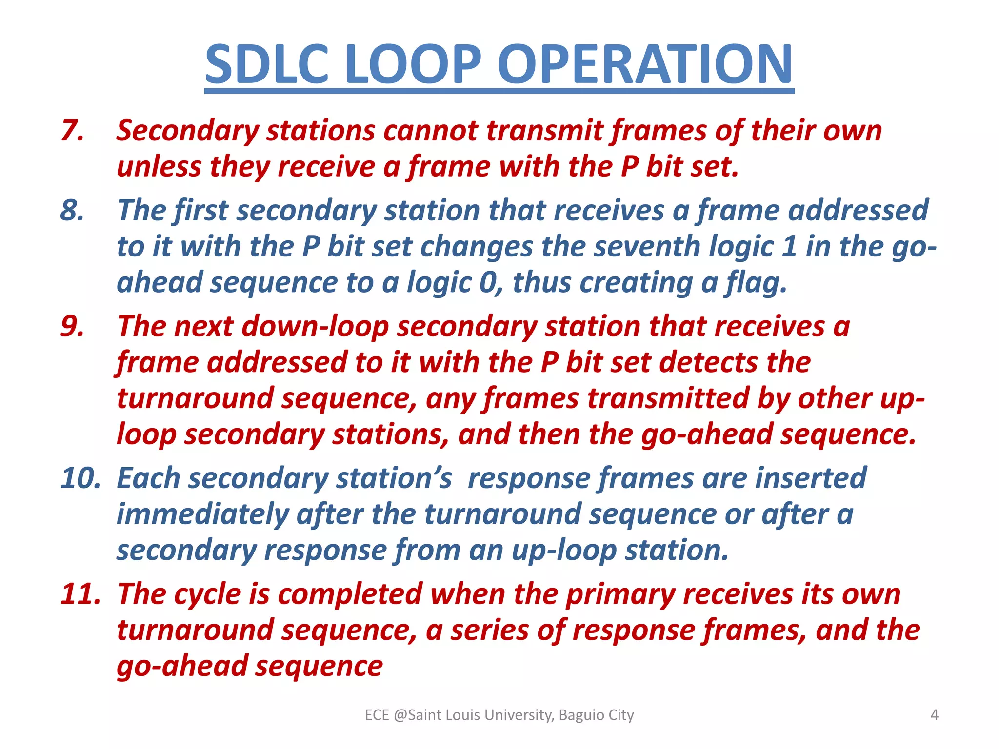
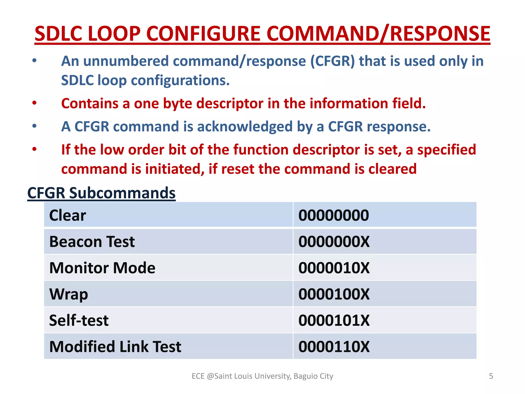
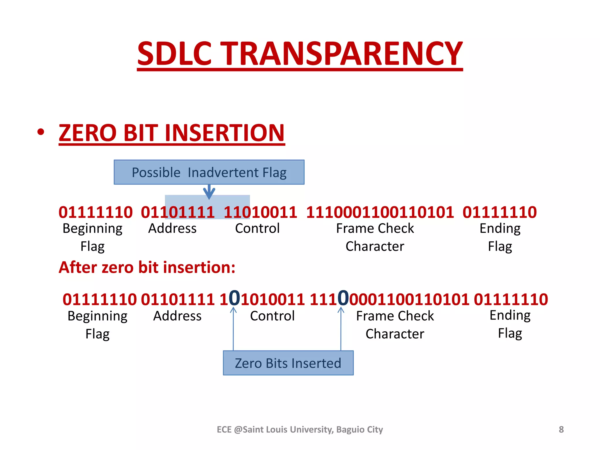

The document details the operations of the Synchronous Data Link Control (SDLC) loop, including management of primary and secondary station communications, frame transmission protocols, and command-response configurations. It also covers error correction methods such as zero-bit insertion for transparency and emergency response mechanisms, as well as the High-Level Data Link Control (HDLC) standards that extend SDLC capabilities. Various operational modes of HDLC, including Asynchronous Response Mode and Asynchronous Balanced Mode, are also described.