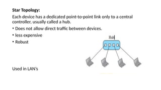
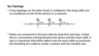
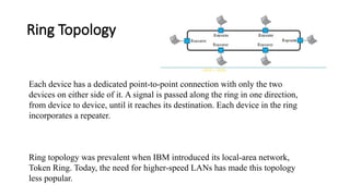
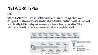
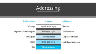
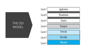
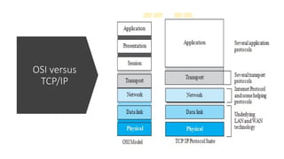
DATA
COMMUNICATIONS
DATA - refers to information presented in whatever form
is agreed upon by the parties creating and using the data.
COMMUNICATION- Exchange of data between two
devices via some form of transmission medium such as a
wire cable.
Four fundamental characteristics:
1. Delivery
2. Accuracy
3. Timeliness
4. Jitter.
1. Delivery - The system must deliver data to the correct destination.
Data must be received by the intended device or user and only by
that device or user.
2. Accuracy - The system must deliver the data accurately. Data that
have been altered in transmission and left uncorrected are unusable.
3. Timeliness - The system must deliver data in a timely manner. Data
delivered late are useless.
4. Jitter - Jitter refers to the variation in the packet arrival time. It is the
uneven delay in the delivery of audio or video packets.
COMPONENTS
Message. The message is the information (data) to be communicated. Popular
forms of information include text, numbers, pictures, audio, and video.
Sender. The sender is the device that sends the data message. It can be a
computer, workstation, telephone handset, video camera, and so on.
Receiver. The receiver is the device that receives the message. It can be a
computer, workstation, telephone handset, television, and so on.
Transmission medium. The transmission medium is the physical path by which a message
travels from sender to receiver. Protocol. A protocol is a set of rules that govern data
communications. It represents an agreement between the communicating devices.
DATA REPRESENTATION
1. Text - In data communications, text is represented as a bit pattern, a
sequence of bits (0s or 1s). Different sets of bit patterns have been
designed to represent text symbols. Each set is called a code, and the
process of representing symbols is called coding.
2. Numbers - Numbers are also represented by bit patterns. However, a code
such as ASCII is not used to represent numbers; the number is directly
converted to a binary number to simplify mathematical operations.
3. Images - Images are also represented by bit patterns. In its simplest form,
an image is composed of a matrix of pixels (picture elements), where each
pixel is a small dot. The size of the pixel depends on the resolution. For
example, an image can be divided into 1000 pixels or 10,000 pixels.
There are several methods to represent color images.
• One method is called RGB, so called because each color is made of a
combination of three primary colors: red, green, and blue. The
intensity of each color is measured, and a bit pattern is assigned to it.
• Another method is called YCM, in which a color is made of a
combination of three other primary colors: yellow, cyan, and magenta.
4. Audio- refers to the recording or broadcasting of sound or music.
Audio is by nature different from text, numbers, or images. It is
continuous, not discrete.
5. Video - Video refers to the recording or broadcasting of a picture or
movie. Video can either be produced as a continuous entity (e.g., by a
TV camera), or it can be a combination of images, each a discrete entity,
arranged to convey the idea of motion.
Data Flow
NETWORKS
• A network is the interconnection of a set of devices capable of
communication.
• Device can be a host such as a large computer, desktop, laptop,
workstation, cellular phone, or security system.
• It can also be a connecting device such as a router, which connects
the network to other networks, a switch, which connects devices
together, a modem (modulator-demodulator), which changes the
form of data, and so on.
• Connected using wired or wireless transmission media such as cable
or air. When we connect two computers at home using a plug-and-
play router, we have created a network, although very small.
Network Criteria
• Performance - Measured with transit time and response time.
1. Transit time is the amount of time required for a message to travel from one
device to another.
2. Response time is the elapsed time between an inquiry and a response. The
performance of a network depends on a number of factors
• Reliability- Network reliability is measured by the frequency of failure, the time it
takes a link to recover from a failure, and the network’s robustness in a
catastrophe.
• Security - Network security issues include protecting data from unauthorized
access, protecting data from damage and development, and implementing policies
and procedures for recovery from breaches and data losses.
PHYSICAL STRUCTURES
A network is two or more devices connected through links. A link is a communications pathway that
transfers data from one device to another. For visualization purposes, it is simplest to imagine any
link as a line drawn between two points. For communication to occur, two devices must be
connected in some way to the same link at the same time. There are two possible types of
connections: point-to point and multipoint.
Point to Point:
Multipoint
Physical Topology
The term physical topology refers to the way in which a network is laid out
physically. Two or more devices connect to a link; two or more links form a
topology. There are four basic topologies:
• Mesh
• Star
• Bus
• Ring.
Mesh Topology:
Every device has a dedicated point-to-point link to every other device
• Each connection can carry its own data load, thus eliminating the
traffic problems that can occur when links must be shared by multiple
devices.
• Robust
• Gives privacy or security
Connection of telephone regional offices in which each regional office
needs to be connected to every other regional office.
Star Topology:
Each device has a dedicated point-to-point link only to a central
controller, usually called a hub.
• Does not allow direct traffic between devices.
• less expensive
• Robust
Used in LAN’s
Bus Topology:
• A bus topology, on the other hand, is multipoint. One long cable acts
as a backbone to link all the devices in a network.
• Nodes are connected to the bus cable by drop lines and taps. A drop
line is a connection running between the device and the main cable. A
tap is a connector that either splices into the main cable or punctures
the sheathing of a cable to create a contact with the metallic core.
Ring Topology
Each device has a dedicated point-to-point connection with only the two
devices on either side of it. A signal is passed along the ring in one direction,
from device to device, until it reaches its destination. Each device in the ring
incorporates a repeater.
Ring topology was prevalent when IBM introduced its local-area network,
Token Ring. Today, the need for higher-speed LANs has made this topology
less popular.
NETWORK TYPES
LAN
When LANs were used in isolation (which is rare today), they were
designed to allow resources to be shared between the hosts. As we will
see shortly, LANs today are connected to each other and to WANs
(discussed next) to create communication at a wider level.
WAN
• A wide area network (WAN) is also an interconnection of devices
capable of communication.
• WAN has a wider geographical span, spanning a town, a state, a
country, or even the world. A LAN interconnects hosts; a WAN
interconnects connecting devices such as switches, routers, or
modems.
• A LAN is normally privately owned by the organization that uses it; a
WAN is normally created and run by communication companies and
leased by an organization that uses it. We see two distinct examples
of WANs today: point-to-point WANs and switched WANs.
Point-to-Point WAN
A point-to-point WAN is a network that connects two communicating
devices through a trans- mission media (cable or air). We will see
examples of these WANs when we discuss how to connect the
networks to one another.
Switched WAN
• A switched WAN is a network with more than two ends. A switched
WAN, as we will see shortly, is used in the backbone of global
communication today. We can say that a switched WAN is a
combination of several point-to-point WANs that are connected by
switches..
Internetwork
When two or more networks are connected, they make an
internetwork, or internet. As an example, assume that an
organization has two offices, one on the east coast and the other on
the west coast.
Switching
• An internet is a switched network in which a switch connects at least
two links together. A switch needs to forward data from a network to
another network when required.
Circuit-Switched Network
Packet-Switched Network
In a computer network, the
communication between the two
ends is done in blocks of data
called packets. This allows us to
make the switches function for
both storing and forwarding
because a packet is an
independent entity that can be
stored and sent later.
The Internet
Backbones and provider
networks are also called
Internet Service Providers
(ISPs). The backbones are
often referred to as
international ISPs; the
provider networks are often
referred to as national or
regional ISPs.
PROTOCOL LAYERING
A single-layer protocol
A three-layer protocol
Principles of Protocol Layering
First Principle
The first principle dictates that if we want bidirectional communication,
we need to make each layer so that it is able to perform two opposite
tasks, one in each direction. For example, the third layer task is to listen
(in one direction) and talk (in the other direction). The second layer
needs to be able to encrypt and decrypt. The first layer needs to send
and receive mail.
Second Principle
The second principle that we need to follow in protocol layering is that
the two objects under each layer at both sites should be identical. For
example, the object under layer 3 at both sites should be a plaintext
letter. The object under layer 2 at both sites should be a cipher text
letter. The object under layer 1 at both sites should be a piece of mail.
Logical Connections
TCP/IP PROTOCOL SUITE
Layered Architecture
• The router is involved in
only three layers; there
is no transport or
application layer in a
router as long as the
router is used only for
routing.
• A link-layer switch in a
link, however, is
involved only in two
layers, data-link and
physical.
Layers in the TCP/IP Protocol Suite
Description of Each Layer
• Physical Layer
• Data-link Layer
• Network Layer
• Transport Layer
• Application Layer
Physical Layer
• Responsible for carrying individual bits in a frame across the link.
Although the physical layer is the lowest level in the TCP/IP protocol
suite, the communication between two devices at the physical layer is
still a logical communication because there is another, hidden layer,
the transmission media, under the physical layer.
• Two devices are connected by a transmission medium (cable or air).
Data Link Layer
• An internet is made up of several links (LANs and WANs) connected by
routers. There may be several overlapping sets of links that a datagram
can travel from the host to the destination.
• The routers are responsible for choosing the best links. However, when
the next link to travel is determined by the router, the data-link layer is
responsible for taking the datagram and moving it across the link.
• TCP/IP does not define any specific protocol for the data-link layer. It
supports all the standard and proprietary protocols. Any protocol that
can take the datagram and carry it through the link suffices for the
network layer. The data-link layer takes a datagram and encapsulates it
in a packet called a frame.
Network Layer
• The network layer is responsible for creating a connection between
the source computer and the destination computer. The
communication at the network layer is host-to-host.
• The network layer is responsible for host-to-host communication and
routing the packet through possible routes.
• The network layer in the Internet includes the main protocol, Internet
Protocol (IP), that defines the format of the packet, called a datagram
at the network layer. IP also defines the format and the structure of
addresses used in this layer
Transport Layer
• The logical connection at the transport layer is also end-to-end.
• The transport layer at the source host gets the message from the
application layer, encapsulates it in a transport- layer packet (called a
segment or a user datagram in different protocols) and sends it,
through the logical (imaginary) connection, to the transport layer at
the destination host.
• In other words, the transport layer is responsible for giving services to
the application layer: to get a message from an application program
running on the source host and deliver it to the corresponding
application program on the destination host.
Application Layer
• The Hypertext Transfer Protocol (HTTP) is a vehicle for accessing the World Wide
Web (WWW).
• The Simple Mail Transfer Protocol (SMTP) is the main protocol used in electronic
mail (e-mail) service. The File Transfer Protocol (FTP) is used for transferring files
from one host to another.
• The Terminal Network (TELNET) and Secure Shell (SSH) are used for accessing a site
remotely. The Simple Network Management Protocol (SNMP) is used by an
administrator to manage the Internet at global and local levels.
• The Domain Name System (DNS) is used by other protocols to find the network-layer
address of a computer.
• The Internet Group Management Protocol (IGMP) is used to collect membership in a
group.
Encapsulation and Decapsulation
Addressing
Multiplexing
Demultiplexing
THE OSI
MODEL
OSI versus
TCP/IP
Lack of OSI Model’s Success
• First, OSI was completed when TCP/IP was fully in place and a lot of time
and money had been spent on the suite; changing it would cost a lot.
• Second, some layers in the OSI model were never fully defined.
For example, although the services provided by the presentation and the
session layers were listed in the document, actual protocols for these two
layers were not fully defined, nor were they fully described, and the
corresponding software was not fully developed.
Third, when OSI was implemented by an organization in a different
application, it did not show a high enough level of performance to entice the
Internet authority to switch from the TCP/IP protocol suite to the OSI model

Data communications module 1 for ece students

  • 1.
    DATA COMMUNICATIONS DATA - refersto information presented in whatever form is agreed upon by the parties creating and using the data. COMMUNICATION- Exchange of data between two devices via some form of transmission medium such as a wire cable. Four fundamental characteristics: 1. Delivery 2. Accuracy 3. Timeliness 4. Jitter.
  • 2.
    1. Delivery -The system must deliver data to the correct destination. Data must be received by the intended device or user and only by that device or user. 2. Accuracy - The system must deliver the data accurately. Data that have been altered in transmission and left uncorrected are unusable. 3. Timeliness - The system must deliver data in a timely manner. Data delivered late are useless. 4. Jitter - Jitter refers to the variation in the packet arrival time. It is the uneven delay in the delivery of audio or video packets.
  • 3.
    COMPONENTS Message. The messageis the information (data) to be communicated. Popular forms of information include text, numbers, pictures, audio, and video. Sender. The sender is the device that sends the data message. It can be a computer, workstation, telephone handset, video camera, and so on. Receiver. The receiver is the device that receives the message. It can be a computer, workstation, telephone handset, television, and so on. Transmission medium. The transmission medium is the physical path by which a message travels from sender to receiver. Protocol. A protocol is a set of rules that govern data communications. It represents an agreement between the communicating devices.
  • 4.
    DATA REPRESENTATION 1. Text- In data communications, text is represented as a bit pattern, a sequence of bits (0s or 1s). Different sets of bit patterns have been designed to represent text symbols. Each set is called a code, and the process of representing symbols is called coding. 2. Numbers - Numbers are also represented by bit patterns. However, a code such as ASCII is not used to represent numbers; the number is directly converted to a binary number to simplify mathematical operations. 3. Images - Images are also represented by bit patterns. In its simplest form, an image is composed of a matrix of pixels (picture elements), where each pixel is a small dot. The size of the pixel depends on the resolution. For example, an image can be divided into 1000 pixels or 10,000 pixels.
  • 5.
    There are severalmethods to represent color images. • One method is called RGB, so called because each color is made of a combination of three primary colors: red, green, and blue. The intensity of each color is measured, and a bit pattern is assigned to it. • Another method is called YCM, in which a color is made of a combination of three other primary colors: yellow, cyan, and magenta. 4. Audio- refers to the recording or broadcasting of sound or music. Audio is by nature different from text, numbers, or images. It is continuous, not discrete. 5. Video - Video refers to the recording or broadcasting of a picture or movie. Video can either be produced as a continuous entity (e.g., by a TV camera), or it can be a combination of images, each a discrete entity, arranged to convey the idea of motion.
  • 6.
  • 7.
    NETWORKS • A networkis the interconnection of a set of devices capable of communication. • Device can be a host such as a large computer, desktop, laptop, workstation, cellular phone, or security system. • It can also be a connecting device such as a router, which connects the network to other networks, a switch, which connects devices together, a modem (modulator-demodulator), which changes the form of data, and so on. • Connected using wired or wireless transmission media such as cable or air. When we connect two computers at home using a plug-and- play router, we have created a network, although very small.
  • 8.
    Network Criteria • Performance- Measured with transit time and response time. 1. Transit time is the amount of time required for a message to travel from one device to another. 2. Response time is the elapsed time between an inquiry and a response. The performance of a network depends on a number of factors • Reliability- Network reliability is measured by the frequency of failure, the time it takes a link to recover from a failure, and the network’s robustness in a catastrophe. • Security - Network security issues include protecting data from unauthorized access, protecting data from damage and development, and implementing policies and procedures for recovery from breaches and data losses.
  • 9.
    PHYSICAL STRUCTURES A networkis two or more devices connected through links. A link is a communications pathway that transfers data from one device to another. For visualization purposes, it is simplest to imagine any link as a line drawn between two points. For communication to occur, two devices must be connected in some way to the same link at the same time. There are two possible types of connections: point-to point and multipoint. Point to Point:
  • 10.
    Multipoint Physical Topology The termphysical topology refers to the way in which a network is laid out physically. Two or more devices connect to a link; two or more links form a topology. There are four basic topologies: • Mesh • Star • Bus • Ring.
  • 11.
    Mesh Topology: Every devicehas a dedicated point-to-point link to every other device • Each connection can carry its own data load, thus eliminating the traffic problems that can occur when links must be shared by multiple devices. • Robust • Gives privacy or security Connection of telephone regional offices in which each regional office needs to be connected to every other regional office.
  • 12.
    Star Topology: Each devicehas a dedicated point-to-point link only to a central controller, usually called a hub. • Does not allow direct traffic between devices. • less expensive • Robust Used in LAN’s
  • 13.
    Bus Topology: • Abus topology, on the other hand, is multipoint. One long cable acts as a backbone to link all the devices in a network. • Nodes are connected to the bus cable by drop lines and taps. A drop line is a connection running between the device and the main cable. A tap is a connector that either splices into the main cable or punctures the sheathing of a cable to create a contact with the metallic core.
  • 14.
    Ring Topology Each devicehas a dedicated point-to-point connection with only the two devices on either side of it. A signal is passed along the ring in one direction, from device to device, until it reaches its destination. Each device in the ring incorporates a repeater. Ring topology was prevalent when IBM introduced its local-area network, Token Ring. Today, the need for higher-speed LANs has made this topology less popular.
  • 15.
    NETWORK TYPES LAN When LANswere used in isolation (which is rare today), they were designed to allow resources to be shared between the hosts. As we will see shortly, LANs today are connected to each other and to WANs (discussed next) to create communication at a wider level.
  • 16.
    WAN • A widearea network (WAN) is also an interconnection of devices capable of communication. • WAN has a wider geographical span, spanning a town, a state, a country, or even the world. A LAN interconnects hosts; a WAN interconnects connecting devices such as switches, routers, or modems. • A LAN is normally privately owned by the organization that uses it; a WAN is normally created and run by communication companies and leased by an organization that uses it. We see two distinct examples of WANs today: point-to-point WANs and switched WANs.
  • 17.
    Point-to-Point WAN A point-to-pointWAN is a network that connects two communicating devices through a trans- mission media (cable or air). We will see examples of these WANs when we discuss how to connect the networks to one another.
  • 18.
    Switched WAN • Aswitched WAN is a network with more than two ends. A switched WAN, as we will see shortly, is used in the backbone of global communication today. We can say that a switched WAN is a combination of several point-to-point WANs that are connected by switches..
  • 19.
    Internetwork When two ormore networks are connected, they make an internetwork, or internet. As an example, assume that an organization has two offices, one on the east coast and the other on the west coast.
  • 20.
    Switching • An internetis a switched network in which a switch connects at least two links together. A switch needs to forward data from a network to another network when required. Circuit-Switched Network
  • 21.
    Packet-Switched Network In acomputer network, the communication between the two ends is done in blocks of data called packets. This allows us to make the switches function for both storing and forwarding because a packet is an independent entity that can be stored and sent later.
  • 22.
    The Internet Backbones andprovider networks are also called Internet Service Providers (ISPs). The backbones are often referred to as international ISPs; the provider networks are often referred to as national or regional ISPs.
  • 23.
    PROTOCOL LAYERING A single-layerprotocol A three-layer protocol
  • 24.
    Principles of ProtocolLayering First Principle The first principle dictates that if we want bidirectional communication, we need to make each layer so that it is able to perform two opposite tasks, one in each direction. For example, the third layer task is to listen (in one direction) and talk (in the other direction). The second layer needs to be able to encrypt and decrypt. The first layer needs to send and receive mail. Second Principle The second principle that we need to follow in protocol layering is that the two objects under each layer at both sites should be identical. For example, the object under layer 3 at both sites should be a plaintext letter. The object under layer 2 at both sites should be a cipher text letter. The object under layer 1 at both sites should be a piece of mail.
  • 25.
  • 26.
  • 27.
    • The routeris involved in only three layers; there is no transport or application layer in a router as long as the router is used only for routing. • A link-layer switch in a link, however, is involved only in two layers, data-link and physical.
  • 28.
    Layers in theTCP/IP Protocol Suite
  • 30.
    Description of EachLayer • Physical Layer • Data-link Layer • Network Layer • Transport Layer • Application Layer
  • 31.
    Physical Layer • Responsiblefor carrying individual bits in a frame across the link. Although the physical layer is the lowest level in the TCP/IP protocol suite, the communication between two devices at the physical layer is still a logical communication because there is another, hidden layer, the transmission media, under the physical layer. • Two devices are connected by a transmission medium (cable or air).
  • 32.
    Data Link Layer •An internet is made up of several links (LANs and WANs) connected by routers. There may be several overlapping sets of links that a datagram can travel from the host to the destination. • The routers are responsible for choosing the best links. However, when the next link to travel is determined by the router, the data-link layer is responsible for taking the datagram and moving it across the link. • TCP/IP does not define any specific protocol for the data-link layer. It supports all the standard and proprietary protocols. Any protocol that can take the datagram and carry it through the link suffices for the network layer. The data-link layer takes a datagram and encapsulates it in a packet called a frame.
  • 33.
    Network Layer • Thenetwork layer is responsible for creating a connection between the source computer and the destination computer. The communication at the network layer is host-to-host. • The network layer is responsible for host-to-host communication and routing the packet through possible routes. • The network layer in the Internet includes the main protocol, Internet Protocol (IP), that defines the format of the packet, called a datagram at the network layer. IP also defines the format and the structure of addresses used in this layer
  • 34.
    Transport Layer • Thelogical connection at the transport layer is also end-to-end. • The transport layer at the source host gets the message from the application layer, encapsulates it in a transport- layer packet (called a segment or a user datagram in different protocols) and sends it, through the logical (imaginary) connection, to the transport layer at the destination host. • In other words, the transport layer is responsible for giving services to the application layer: to get a message from an application program running on the source host and deliver it to the corresponding application program on the destination host.
  • 35.
    Application Layer • TheHypertext Transfer Protocol (HTTP) is a vehicle for accessing the World Wide Web (WWW). • The Simple Mail Transfer Protocol (SMTP) is the main protocol used in electronic mail (e-mail) service. The File Transfer Protocol (FTP) is used for transferring files from one host to another. • The Terminal Network (TELNET) and Secure Shell (SSH) are used for accessing a site remotely. The Simple Network Management Protocol (SNMP) is used by an administrator to manage the Internet at global and local levels. • The Domain Name System (DNS) is used by other protocols to find the network-layer address of a computer. • The Internet Group Management Protocol (IGMP) is used to collect membership in a group.
  • 36.
  • 37.
  • 38.
  • 39.
  • 40.
  • 41.
  • 42.
    Lack of OSIModel’s Success • First, OSI was completed when TCP/IP was fully in place and a lot of time and money had been spent on the suite; changing it would cost a lot. • Second, some layers in the OSI model were never fully defined. For example, although the services provided by the presentation and the session layers were listed in the document, actual protocols for these two layers were not fully defined, nor were they fully described, and the corresponding software was not fully developed. Third, when OSI was implemented by an organization in a different application, it did not show a high enough level of performance to entice the Internet authority to switch from the TCP/IP protocol suite to the OSI model