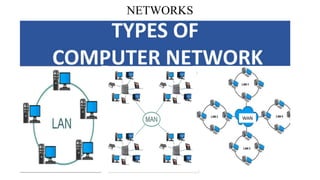
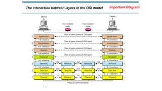
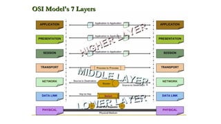
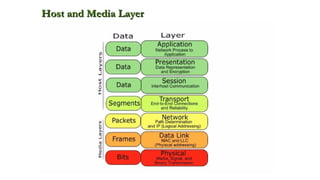
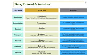
RajaRajeswari College of Engineering
DEPARTMENT OF COMPUTER SCIENCE AND ENGINEERING
Affiliated to Visvesvaraya Technological University “Jnana Sangama”, Belgaum – 560 018
Department of MCA
Prof. Shreedhar Kumbhar
Subject Name: “Computer Networks”
Subject Code: “22MCA14”
“Module-1”
Semester: I
DATA COMMUNICATIONS
1-1 DATA COMMUNICATIONS
The term telecommunication means communication at a
distance. The word data refers to information presented in
whatever form is agreed upon by the parties creating and
using the data.
Data communications are the exchange of data between
two devices via some form of transmission medium such as
a wire cable or wireless.
1. Delivery → Correct destination
2. Accuracy → Accurate data
3. Timelines → Real-time transmission
4. Jitter → Uneven delay
1.3
Figure 1.1 Five components of data communication
Components
Data Representation
Data Flow
Topics discussed in this section:
Components
2
1
3
4
5
1.4
DATA COMMUNICATIONS
DATA COMMUNICATIONS
DATA COMMUNICATIONS
Data Representation:
• Information today comes in different forms such as text, numbers, images, audio, and
video.
1) Text: Character data is composed of letters, symbols, and numerals.
• Examples of character data include your name, address.
• Character data is commonly referred to as “text.”
• The ASCII code for an uppercase A is 1000001.
DATA COMMUNICATIONS
ASCII values of Characters:
DATA COMMUNICATIONS
• 2) Numbers: Numeric data consists of numbers that can be used in arithmetic operations.
• Digital devices represent numeric data using the binary number system, also called base 2.
• The binary number system only has two digits: 0 and 1.
• No numeral like 2 exists in the system, so the number “two” is represented in binary as 10
(pronounced “one zero”).
DATA COMMUNICATIONS
DATA COMMUNICATIONS
3) Images are also represented by bit patterns. In its simplest form, an image is composed of a matrix of pixels
(picture elements), where each pixel is a small dot.
• The size of the pixel depends on the resolution. For example, an image can be divided into 1000 pixels or 10,000
pixels.
• In the second case, there is a better representation of the image (better resolution), but more memory is needed to
store the image.
• There are several methods to represent color images. One method is called RGB, so called because each color is made
of a combination of three primary colors: red, green, and blue.
DATA COMMUNICATIONS
NETWORKS
1-2 NETWORKS
A network is a set of devices (nodes) connected by
communication links. A node can be a computer, printer, or
any other device capable of sending and/or receiving data
generated by other nodes on the network.
1.14
NETWORKS
NETWORKS
1) Simplex In simplex mode, the communication is unidirectional, as on a one-way street.
• Only one of the two devices on a link can transmit; the other can only receive.
• Keyboards and traditional monitors are examples of simplex devices.
• The keyboard can only introduce input; the monitor can only accept output.
NETWORKS
2) Half-Duplex In half-duplex mode, each station can both transmit and receive, but not at the same time.
• When one device is sending, the other can only receive, and vice versa.
• In a half-duplex transmission, the entire capacity of a channel is taken over by whichever of the two devices
is transmitting at the time.
• Walkie-talkies and CB (citizens band) radios are both half-duplex systems.
• The half-duplex mode is used in cases where there is no need for communication in both directions at the
same time; the entire capacity of the channel can be utilized for each direction.
NETWORKS
3) full-duplex : both stations can transmit and receive simultaneously.
• In full-duplex mode, signals going in one direction share the capacity of the link with signals going in the other
direction.
• This sharing can occur in two ways: Either the link must contain two physically separate transmission paths.
• one for sending and the other for receiving; or the capacity of the channel is divided between signals
travelling in both directions.
• One common example of full-duplex communication is the telephone network.
Types of connections
 Point to point
 A dedicated link is provided
between two devices
 Multipoint
 More than two specific devices
share a single link
1.19
NETWORKS
NETWORKS
NETWORKS
NETWORKS
NETWORKS
NETWORKS
NETWORKS
NETWORKS
NETWORKS
NETWORKS
NETWORKS
NETWORKS
NETWORKS
NETWORKS
NETWORKS
NETWORKS
NETWORKS
NETWORKS
NETWORKS
NETWORKS
NETWORKS
NETWORKS
NETWORKS
NETWORKS
NETWORKS
NETWORKS
NETWORKS
NETWORKS
NETWORKS
NETWORKS
NETWORKS
NETWORKS
NETWORKS
NETWORKS
NETWORKS
NETWORKS
NETWORKS
Categories of Networks
1) Local Area Network :(LAN) is usually privately owned and links the devices in a single office,
building, or campus.
• LAN can be as simple as two PCs and a printer in someone's home office; or it can extend
throughout a company and include audio and video peripherals.
• Currently, LAN size is limited to a few kilometers. LANs are designed to allow resources to be
shared between personal computers or workstations.
NETWORKS
Local Area Network
NETWORKS
• 2) Metropolitan area network (MAN): is a network with a size between a LAN and a WAN.
• It normally covers the area inside a town or a city.
• It is designed for customers who need a high- speed connectivity, normally to the Internet, and
have endpoints spread over a city or part of city.
• A good example of a MAN is the part of the telephone company network that can provide a
high-speed DSL line to the customer.
NETWORKS
NETWORKS
3) Wide Area Network :A wide area network (WAN) provides long-distance transmission of data, image, audio, and video information
over large geographic areas that may comprise a country, a continent, or even the whole world.
• We normally refer to the first as a switched WAN and to the second as a point-to-point WAN.
• The switched WAN connects the end systems, which usually comprise a router (internet-working connecting device) that
connects to another LAN or WAN.
• The point-to-point WAN is normally a line leased from a telephone or cable TV provider that connects a home computer or a
small LAN to an Internet service provider (ISP). This type of WAN is often used to provide Internet access.
WANs: a switched WAN and a point-to-point WAN
1.61
A heterogeneous network made of four WANs and two LANs
Interconnection of Networks: internet
1.62
THE INTERNET
The Internet has changed many aspects of our daily lives. It
has affected the way we do business as well as the way we
spend our leisure time. The Internet is a communication
system that has brought a wealth of information to our
fingertips and organized it for our use.
A Brief History → ARPANET
• 1967 ACM
• 1969 UCLA, UCSB, SRI, UoU
• 1972 TCP
The Internet Today (ISPs)
Topics discussed in this section:
1.63
Hierarchical organization of the Internet
1.64
PROTOCOLS AND STANDARDS
protocols and standards.
Protocol is synonymous with rule.
Standards are agreed-upon rules.
1.65
PROTOCOLS AND STANDARDS
Protocols
• Syntax → format of the data
• Semantics → meaning of each section
• Timing → when data should be sent and how fast.
Standards
• De facto → by fact (not approved as a standard)
• De jure → by Law (approved)
1.66
PROTOCOLS AND STANDARDS
Standards Organizations
• International Organization for Standardization (ISO)
• International Telecommunication Union - Telecommunication
Standards (ITU-T)
• American National Standards Institute (ANSI)
• Institute of Electrical and Electronics Engineers (IEEE)
• Electronic Industries Association (EIA)
LAYERED TASKS
 A network model is a layered architecture
 Task broken into subtasks
 Implemented separately in layers in stack
 Functions need in both systems
 Peer layers communicate
 Protocol:
 A set of rules that governs data communication
 It represents an agreement between the communicating devices
1.68
Tasks involved in sending a letter
Sender, Receiver, and Carrier
Hierarchy (services)
Topics discussed in this section:
1.69
Seven layers of the OSI model
Layered Architecture
Layers
Layer 7. Application
Layer 6. Presentation
Layer 5. Session
Layer 4. Transport
Layer 3. Network
Layer 2. Data Link
Layer 1. Physical Sender
Receiver
1.71
Layered Architecture
 A layered model
 Each layer performs a subset of the required
communication functions
 Each layer relies on the next lower layer to perform
more primitive functions
 Each layer provides services to the next higher layer
 Changes in one layer should not require changes in
other layers
 The processes on each machine at a given layer are
called peer-to-peer process
1.72
 Communication must move downward through the layers on
the sending device, over the communication channel, and
upward to the receiving device
 Each layer in the sending device adds its own information to
the message it receives from the layer just above it and passes
the whole package to the layer just below it
 At the receiving device, the message is unwrapped layer by
layer, with each process receiving and removing the data
meant for it
PEER – TO – PEER PROCESS
1.73
PEER – TO – PEER PROCESS
 The passing of the data and network information down
through the layers of the sending device and backup through
the layers of the receiving device is made possible by interface
between each pair of adjacent layers
 Interface defines what information and services a layer must
provide for the layer above it.
1.74
The interaction between layers in the OSI model
1.75
An exchange using the OSI model
1.76
The interaction between layers in the OSI model
1.78
Important Diagram
Hop-to-hop delivery
1.84
EXTRA SLIDE
Example 1
In following Figure a node with physical address 10 sends a frame to a node
with physical address 87. The two nodes are connected by a link. At the data
link level this frame contains physical addresses in the header. These are the
only addresses needed. The rest of the header contains other information
needed at this level. The trailer usually contains extra bits needed for error
detection
1.85
EXTRA SLIDE
Source-to-destination delivery
1.87
EXTRA SLIDE
Reliable process-to-process delivery of a message
1.89
EXTRA SLIDE
Summary of layers
OSI Model
Data
unit
Layer Function
User
support
layers
Data
7. Application Network process to application
6. Presentation Data representation and encryption
5. Session Inter-host communication
User
Network
Segment 4. Transport End-to-end connections and reliability
Network
support
layers
Packet 3. Network
Path determination and logical
addressing
Frame 2. Data Link Physical addressing
Bit 1. Physical Media, signal and binary transmission
Sender
Receiver
TCP/IP PROTOCOL SUITE
TCP/IP and OSI model
OSI
Model
TCP/IP
Model
ADDRESSING
ADDRESSING
Four levels of addresses are used in an internet
employing the TCP/IP protocols: physical, logical,
port, and specific.
Physical Addresses
Logical Addresses
Port Addresses
Specific Addresses
Topics discussed in this section:
Addresses in TCP/IP
Relationship of layers and addresses in TCP/IP
Physical addresses are imprinted on the
NIC. Most local-area networks (Ethernet)
use a 48-bit (6-byte) physical address written
as 12 hexadecimal digits; every byte (2
hexadecimal digits) is separated by a colon.
Physical Address
Example:
07:01:02:01:2C:4B
A 6-byte (12 hexadecimal digits) physical
address.
The physical addresses in the datagram may change
from hop to hop.
• known also as the MAC address
• Is the address of a node as defined by its
LAN or WAN
• It is included in the frame used by data link
layer
Physical Address
The physical addresses will change from hop to hop,
but the logical addresses usually remain the same.
 IP addresses are necessary for universal
communications that are independent of physical
network.
 No two host address on the internet can have the
same IP address
 IP addresses in the Internet are 32-bit address that
uniquely define a host.
Logical Address
Port address is a 16-bit address represented by one decimal
number ranged from (0-65535) to choose a process among
multiple processes on the destination host.
 Destination port number is needed for delivery.
 Source port number is needed for receiving a reply as an
acknowledgments.
In TCP/IP , a 16-bit port address represented
as one single number. Example: 753
The physical addresses change from hop to hop,
but the logical and port addresses usually remain the same.
Port addresses
Port addresses
Computer Network Module 1 (Complete).pptx

Computer Network Module 1 (Complete).pptx

  • 1.
    RajaRajeswari College ofEngineering DEPARTMENT OF COMPUTER SCIENCE AND ENGINEERING Affiliated to Visvesvaraya Technological University “Jnana Sangama”, Belgaum – 560 018 Department of MCA Prof. Shreedhar Kumbhar Subject Name: “Computer Networks” Subject Code: “22MCA14” “Module-1” Semester: I
  • 2.
  • 3.
    1-1 DATA COMMUNICATIONS Theterm telecommunication means communication at a distance. The word data refers to information presented in whatever form is agreed upon by the parties creating and using the data. Data communications are the exchange of data between two devices via some form of transmission medium such as a wire cable or wireless. 1. Delivery → Correct destination 2. Accuracy → Accurate data 3. Timelines → Real-time transmission 4. Jitter → Uneven delay 1.3
  • 4.
    Figure 1.1 Fivecomponents of data communication Components Data Representation Data Flow Topics discussed in this section: Components 2 1 3 4 5 1.4
  • 5.
  • 6.
  • 7.
    DATA COMMUNICATIONS Data Representation: •Information today comes in different forms such as text, numbers, images, audio, and video. 1) Text: Character data is composed of letters, symbols, and numerals. • Examples of character data include your name, address. • Character data is commonly referred to as “text.” • The ASCII code for an uppercase A is 1000001.
  • 8.
  • 9.
    DATA COMMUNICATIONS • 2)Numbers: Numeric data consists of numbers that can be used in arithmetic operations. • Digital devices represent numeric data using the binary number system, also called base 2. • The binary number system only has two digits: 0 and 1. • No numeral like 2 exists in the system, so the number “two” is represented in binary as 10 (pronounced “one zero”).
  • 10.
  • 11.
    DATA COMMUNICATIONS 3) Imagesare also represented by bit patterns. In its simplest form, an image is composed of a matrix of pixels (picture elements), where each pixel is a small dot. • The size of the pixel depends on the resolution. For example, an image can be divided into 1000 pixels or 10,000 pixels. • In the second case, there is a better representation of the image (better resolution), but more memory is needed to store the image. • There are several methods to represent color images. One method is called RGB, so called because each color is made of a combination of three primary colors: red, green, and blue.
  • 12.
  • 13.
  • 14.
    1-2 NETWORKS A networkis a set of devices (nodes) connected by communication links. A node can be a computer, printer, or any other device capable of sending and/or receiving data generated by other nodes on the network. 1.14
  • 15.
  • 16.
    NETWORKS 1) Simplex Insimplex mode, the communication is unidirectional, as on a one-way street. • Only one of the two devices on a link can transmit; the other can only receive. • Keyboards and traditional monitors are examples of simplex devices. • The keyboard can only introduce input; the monitor can only accept output.
  • 17.
    NETWORKS 2) Half-Duplex Inhalf-duplex mode, each station can both transmit and receive, but not at the same time. • When one device is sending, the other can only receive, and vice versa. • In a half-duplex transmission, the entire capacity of a channel is taken over by whichever of the two devices is transmitting at the time. • Walkie-talkies and CB (citizens band) radios are both half-duplex systems. • The half-duplex mode is used in cases where there is no need for communication in both directions at the same time; the entire capacity of the channel can be utilized for each direction.
  • 18.
    NETWORKS 3) full-duplex :both stations can transmit and receive simultaneously. • In full-duplex mode, signals going in one direction share the capacity of the link with signals going in the other direction. • This sharing can occur in two ways: Either the link must contain two physically separate transmission paths. • one for sending and the other for receiving; or the capacity of the channel is divided between signals travelling in both directions. • One common example of full-duplex communication is the telephone network.
  • 19.
    Types of connections Point to point  A dedicated link is provided between two devices  Multipoint  More than two specific devices share a single link 1.19
  • 20.
  • 21.
  • 22.
  • 23.
  • 24.
  • 25.
  • 26.
  • 27.
  • 28.
  • 29.
  • 30.
  • 31.
  • 32.
  • 33.
  • 34.
  • 35.
  • 36.
  • 37.
  • 38.
  • 39.
  • 40.
  • 41.
  • 42.
  • 43.
  • 44.
  • 45.
  • 46.
  • 47.
  • 48.
  • 49.
  • 50.
  • 51.
  • 52.
  • 53.
  • 54.
  • 55.
  • 56.
    NETWORKS Categories of Networks 1)Local Area Network :(LAN) is usually privately owned and links the devices in a single office, building, or campus. • LAN can be as simple as two PCs and a printer in someone's home office; or it can extend throughout a company and include audio and video peripherals. • Currently, LAN size is limited to a few kilometers. LANs are designed to allow resources to be shared between personal computers or workstations.
  • 57.
  • 58.
    NETWORKS • 2) Metropolitanarea network (MAN): is a network with a size between a LAN and a WAN. • It normally covers the area inside a town or a city. • It is designed for customers who need a high- speed connectivity, normally to the Internet, and have endpoints spread over a city or part of city. • A good example of a MAN is the part of the telephone company network that can provide a high-speed DSL line to the customer.
  • 59.
  • 60.
    NETWORKS 3) Wide AreaNetwork :A wide area network (WAN) provides long-distance transmission of data, image, audio, and video information over large geographic areas that may comprise a country, a continent, or even the whole world. • We normally refer to the first as a switched WAN and to the second as a point-to-point WAN. • The switched WAN connects the end systems, which usually comprise a router (internet-working connecting device) that connects to another LAN or WAN. • The point-to-point WAN is normally a line leased from a telephone or cable TV provider that connects a home computer or a small LAN to an Internet service provider (ISP). This type of WAN is often used to provide Internet access.
  • 61.
    WANs: a switchedWAN and a point-to-point WAN 1.61
  • 62.
    A heterogeneous networkmade of four WANs and two LANs Interconnection of Networks: internet 1.62
  • 63.
    THE INTERNET The Internethas changed many aspects of our daily lives. It has affected the way we do business as well as the way we spend our leisure time. The Internet is a communication system that has brought a wealth of information to our fingertips and organized it for our use. A Brief History → ARPANET • 1967 ACM • 1969 UCLA, UCSB, SRI, UoU • 1972 TCP The Internet Today (ISPs) Topics discussed in this section: 1.63
  • 64.
  • 65.
    PROTOCOLS AND STANDARDS protocolsand standards. Protocol is synonymous with rule. Standards are agreed-upon rules. 1.65
  • 66.
    PROTOCOLS AND STANDARDS Protocols •Syntax → format of the data • Semantics → meaning of each section • Timing → when data should be sent and how fast. Standards • De facto → by fact (not approved as a standard) • De jure → by Law (approved) 1.66
  • 67.
    PROTOCOLS AND STANDARDS StandardsOrganizations • International Organization for Standardization (ISO) • International Telecommunication Union - Telecommunication Standards (ITU-T) • American National Standards Institute (ANSI) • Institute of Electrical and Electronics Engineers (IEEE) • Electronic Industries Association (EIA)
  • 68.
    LAYERED TASKS  Anetwork model is a layered architecture  Task broken into subtasks  Implemented separately in layers in stack  Functions need in both systems  Peer layers communicate  Protocol:  A set of rules that governs data communication  It represents an agreement between the communicating devices 1.68
  • 69.
    Tasks involved insending a letter Sender, Receiver, and Carrier Hierarchy (services) Topics discussed in this section: 1.69
  • 71.
    Seven layers ofthe OSI model Layered Architecture Layers Layer 7. Application Layer 6. Presentation Layer 5. Session Layer 4. Transport Layer 3. Network Layer 2. Data Link Layer 1. Physical Sender Receiver 1.71
  • 72.
    Layered Architecture  Alayered model  Each layer performs a subset of the required communication functions  Each layer relies on the next lower layer to perform more primitive functions  Each layer provides services to the next higher layer  Changes in one layer should not require changes in other layers  The processes on each machine at a given layer are called peer-to-peer process 1.72
  • 73.
     Communication mustmove downward through the layers on the sending device, over the communication channel, and upward to the receiving device  Each layer in the sending device adds its own information to the message it receives from the layer just above it and passes the whole package to the layer just below it  At the receiving device, the message is unwrapped layer by layer, with each process receiving and removing the data meant for it PEER – TO – PEER PROCESS 1.73
  • 74.
    PEER – TO– PEER PROCESS  The passing of the data and network information down through the layers of the sending device and backup through the layers of the receiving device is made possible by interface between each pair of adjacent layers  Interface defines what information and services a layer must provide for the layer above it. 1.74
  • 75.
    The interaction betweenlayers in the OSI model 1.75
  • 76.
    An exchange usingthe OSI model 1.76
  • 78.
    The interaction betweenlayers in the OSI model 1.78 Important Diagram
  • 84.
  • 85.
    Example 1 In followingFigure a node with physical address 10 sends a frame to a node with physical address 87. The two nodes are connected by a link. At the data link level this frame contains physical addresses in the header. These are the only addresses needed. The rest of the header contains other information needed at this level. The trailer usually contains extra bits needed for error detection 1.85 EXTRA SLIDE
  • 87.
  • 89.
    Reliable process-to-process deliveryof a message 1.89 EXTRA SLIDE
  • 93.
    Summary of layers OSIModel Data unit Layer Function User support layers Data 7. Application Network process to application 6. Presentation Data representation and encryption 5. Session Inter-host communication User Network Segment 4. Transport End-to-end connections and reliability Network support layers Packet 3. Network Path determination and logical addressing Frame 2. Data Link Physical addressing Bit 1. Physical Media, signal and binary transmission Sender Receiver
  • 94.
  • 96.
    TCP/IP and OSImodel OSI Model TCP/IP Model
  • 111.
  • 112.
    ADDRESSING Four levels ofaddresses are used in an internet employing the TCP/IP protocols: physical, logical, port, and specific. Physical Addresses Logical Addresses Port Addresses Specific Addresses Topics discussed in this section:
  • 113.
  • 114.
    Relationship of layersand addresses in TCP/IP
  • 115.
    Physical addresses areimprinted on the NIC. Most local-area networks (Ethernet) use a 48-bit (6-byte) physical address written as 12 hexadecimal digits; every byte (2 hexadecimal digits) is separated by a colon. Physical Address Example: 07:01:02:01:2C:4B A 6-byte (12 hexadecimal digits) physical address.
  • 116.
    The physical addressesin the datagram may change from hop to hop. • known also as the MAC address • Is the address of a node as defined by its LAN or WAN • It is included in the frame used by data link layer Physical Address
  • 117.
    The physical addresseswill change from hop to hop, but the logical addresses usually remain the same.  IP addresses are necessary for universal communications that are independent of physical network.  No two host address on the internet can have the same IP address  IP addresses in the Internet are 32-bit address that uniquely define a host. Logical Address
  • 118.
    Port address isa 16-bit address represented by one decimal number ranged from (0-65535) to choose a process among multiple processes on the destination host.  Destination port number is needed for delivery.  Source port number is needed for receiving a reply as an acknowledgments. In TCP/IP , a 16-bit port address represented as one single number. Example: 753 The physical addresses change from hop to hop, but the logical and port addresses usually remain the same. Port addresses
  • 119.