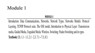
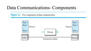
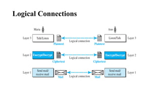
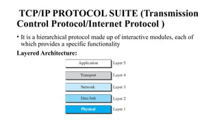
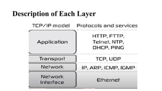
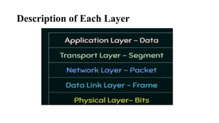
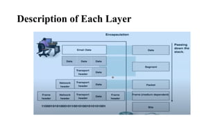
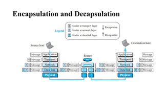
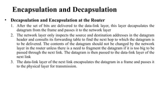
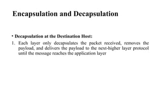
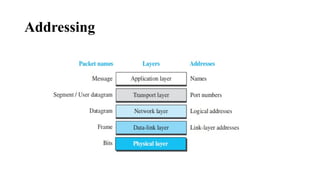
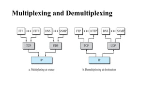
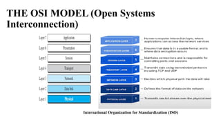
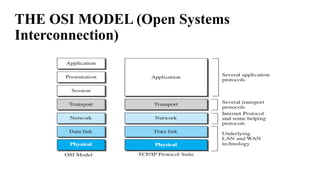
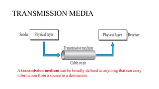
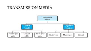
COMPUTER NETWORKS
(BCS502)
Swathy J
Asst. Professor CSE
Cambridge Institute of Technology
Textbook
• Behrouz A. Forouzan, Data Communications and Networking, 5th
Edition, Tata McGraw-Hill,2013
Reference Books:
1. Larry L. Peterson and Bruce S. Davie: Computer Networks – A
Systems Approach, 4th Edition, Elsevier, 2019.
2. Nader F. Mir: Computer and Communication Networks, 2nd
Edition, Pearson Education, 2015.
3. William Stallings, Data and Computer Communication 10th
Edition, Pearson Education, Inc., 2014
Module 1
Data Communications
• Data communications are the exchange of data between two devices via some
form of transmission medium such as a wire cable
• Four fundamental characteristics of Data Communication are:
1. Delivery: The system must deliver data to the correct destination.
2. Accuracy: The system must deliver the data accurately.
3. Timeliness:
• The system must deliver data in a timely manner.
• Data delivered late are useless.
• In the case of video and audio, timely delivery means delivering data as they are produced, in the same
order that they are produced, and without significant delay. This kind of delivery is called real-time
transmission.
4. Jitter:
• Jitter refers to the variation in the packet arrival time.
• For example, let us assume that video packets are sent every 30 ms. If some of the packets arrive
with 30-ms delay and others with 40-ms delay, an uneven quality in the video is the result.
Data Communications- Components
Data Communications- Components(Contd...)
1. Message: The message is the information (data) to be communicated. Popular
forms of information include text, numbers, audio, and video.
2. Sender: The sender is the device that sends the data message. It can be a
computer, workstation etc
3. Receiver: The receiver is the device that receives the message. It can be a
computer, workstation etc.
4. Transmission medium: The transmission medium is the physical path by which
a message travels from sender to receiver. Some examples of transmission media
include twisted-pair wire, coaxial cable, fiber-optic cable, and radio waves.
5. Protocol: A protocol is a set of rules that govern data communications. Without
a protocol, two devices may be connected but not communicating
Data Communications- Data Representation
1. Text:
• Text is represented as a bit pattern, a sequence of bits (0s or 1s)
• Different sets of bit patterns have been designed to represent text symbols. Each set is
called a code, and the process of representing symbols is called coding.
2. Numbers:
• Numbers are also represented by bit patterns and the number is directly converted to a
binary number.
Data Communications- Data Representation
3. Images:
• Images are also represented by bit patterns
• In its simplest form, an image is composed of a matrix of pixels (picture elements), where
each pixel is a small dot. The size of the pixel depends on the resolution
• After an image is divided into pixels, each pixel is assigned a bit pattern.
• If the image made only on black and-white dots (0 or 1)
• In the case of Gray scale
• black pixel - 00
• dark gray pixel- 01
• light gray pixel- 10
• white pixel -11
Data Communications- Data Representation
• RGB : Each color is made of a combination of three primary colors: red,
green, and blue
• YCM : color is made of a combination of three other primary colors: yellow,
cyan, and magenta
4. Video:
• Video refers to the recording or broadcasting of a picture or movie
• It may be a continuous entity or combination of images, arranged to convey the idea of motion
5. Audio :
• Audio refers to the recording or broadcasting of sound or music.
• It is continuous, not discrete
Data Communications-Data Flow
• Simplex :
• Half-duplex
Data Communications-Data Flow
• Full duplex
NETWORKS
• A network is the interconnection of a set of devices capable of
communication
• Device can be a host or node : large computer, desktop, laptop,
workstation, cellular phone, or security system etc
NETWORKS
• Connecting device :
• Router- which connects the network to other networks
• Switch- which connects devices together
• Modem (modulator-demodulator)- which changes the form of data
• Devices in a network are connected using wired or wireless transmission
media such as cable or air
NETWORKS - Network Criteria
• A Network must be able to meet a certain number of criteria
1. Performance
• It measures based on transit time and response time
• Performance is often evaluated by two networking metrics: throughput and delay
⮚ Throughput:Number of bits transmitted in per second
⮚ Delay: time taken to transmit data
2. Reliability
• Reliable networking ensures that data is transmitted accurately, in order, and without
errors between devices or systems.
3. Security
• Protecting data from unauthorized access, protecting data from damage,
development.
NETWORKS -Types of Connection
Types of connection describe the way devices communicate with each other over
a network
• Point-to-Point
• Multipoint or Multidrop
NETWORKS -Types of Connection
• Point-to-Point
• Multipoint or Multidrop
– Dedicated link between two devices
– The entire capacity of the channel is reserved
– Eg., Microwave link, TV remote control
– More than two devices share a single link
– Capacity of the channel is either
• Spatially shared: Devices can use the link simultaneously
• Timeshare: Users must take turns
NETWORKS -Physical Topology
• Physical Topology : Physical arrangement of devices (nodes) in a
network and how they are interconnected.
❖ Four basic topologies:
❖ Mesh Topology
⮚ Find the number of physical links in a fully connected mesh network with n node is n (n – 1)
Advantages:
1. Eliminating the traffic problem
2. Robust- A network to maintain its performance and functionality despite failures, errors, or unpredictable
conditions
3. Privacy or security
4. Fault identification and fault isolation
Disadvantages:
5. Amount of cabling and the number of I/O ports
6. Installation and reconnection
7. Hardware required to connect each link is expensive
NETWORKS -Physical Topology
❖ Star Topology
A hub is a basic networking device used to
connect multiple computers or devices
• Advantages:
1. less expensive than a mesh topology, easy to install and
reconfigure and less cabling needed
2. If one link fails, only that link is affected
• Disadvantage
1. The dependency of the whole topology on one single point,
the hub. If the hub goes down, the whole system is dead.
NETWORKS -Physical Topology
❖Bus Topology
❖ Long cable acts as a backbone to link all the devices in a network
network
• Traditional Ethernet LANs
NETWORKS -Physical Topology
• Advantages:
1. Ease of installation , bus uses less cabling than mesh or
star topologies
• Disadvantage
1. Reconnection and fault isolation
2. Fault or break in the bus cable stops all transmission
3. The damaged area reflects signals back in the direction of
origin, creating noise in both directions - cable damage leads to
signal reflection because the signals are no longer properly terminated at the broken point.
This reflected signal causes noise and collisions, disrupting the entire network's
communication.
❖Ring Topology
• Advantages:
1. A ring is relatively easy to install and reconfigure
2. To add or delete a device requires changing only two
connections.
• Disadvantage
1. Unidirectional traffic
2. A break in the ring (such as a disabled station) can disable
the entire network
This weakness can be solved by using a dual ring or a
switch capable of closing off the break
Network Types- LAN ( Local Area Network)
⮚ In the past, all hosts in a network were connected
through a common cable, which meant that a packet
sent from one host to another was received by all
hosts
⮚ The intended recipient kept the packet; the others
dropped the packet
⮚ Most LANs use a smart connecting switch, which is
able to recognize the destination address of the
packet and guide the packet to its destination
without sending it to all other hosts
Network Types- WAN ( Wide Area Network)
• WAN has a wide geographical span,
spanning a town, a state, a country, or
even the world
• WAN interconnects connecting devices
such as switches, routers, or modems.
• WANs today:
• Point-to-point WANs- Establishes a dedicated and
direct connection between two devices like router,switched etc
• Switched WANs -Uses a shared infrastructure, where
multiple devices or sites are connected through switching
nodes.
point-to-point WAN
Switched WAN
1.27
Network Types- Switching
• Video: https://youtu.be/G7n8thqwO2c?si=iCY9Kk0ECXcPnLAc
• Switching refers to the process of selecting the path that data will take
across a network to reach its destination
• A switch needs to forward data from a network to another network when
required
Two types of switched networks are,
• Circuit-Switched Network
• Packet-Switched Network
• In a circuit-switched network, a dedicated connection, called a circuit, is
always available between the two end systems; the switch can only make it
active or inactive.
Circuit-Switched Network
• Circuit switching was very common in telephone networks in the
past, today we are using packet switching for telephone network
Circuit-Switched Network
• In a computer network, the communication between the two ends is done in
blocks of data called packets.
or
• Packets are small units of data that are transmitted over a network
• A router in a packet-switched network has a queue that can store and
forward the packet.
Packet-Switched Network
1.32
The
Internet
• “Network of networks”
• This phrase highlights how the Internet is not a single network but a
vast, interconnected system of smaller networks (like local area
networks or LANs, wide area networks or WANs, and others) that work
together to form a global communication infrastructure.
1.33
The Internet today
1. Customer Networks:
These are individual networks belonging to users or organizations (e.g., home users,
businesses, educational institutions). These networks rely on Internet service providers
(ISPs) for access to the wider Internet
2. Provider Networks: Provider networks manage traffic between customer networks
and core infrastructure like Internet backbones.
3. Backbones: The backbone represents the core infrastructure of the Internet. These are
high-capacity networks that carry large amounts of traffic across long distances, such as
between cities or countries.
4. Peering points are locations where different networks (such as provider networks and
backbone networks) connect and exchange traffic. These points help ensure that data can
flow efficiently between different networks without bottlenecks.
1.34
The Internet today
Accessing the Internet
• The Internet today is an internetwork that allows any user to become part of it. The user,
however, needs to be physically connected to an ISP. The physical connection is normally
done through a point-to-point WAN.
Using Telephone Networks
• Dial-up service: The first solution is to add to the telephone line a modem that converts
data to voice. The software installed on the computer dials the ISP and imitates making a
telephone connection.
• DSL Service (Digital Subscriber Line): Since the advent of the Internet, some telephone
companies have upgraded their telephone lines to provide higher speed Internet services to
residences or small businesses.
1-42
Using Cable Networks
• More and more residents over the last two decades have begun using cable TV services instead of
antennas to receive TV broadcasting
• The cable companies have been upgrading their cable networks and connecting to the Internet. A
residence or a small business can be connected to the Internet by using this service
• It provides a higher speed connection, but the speed varies depending on the number of neighbors
that use the same cable
Using Wireless Networks
• With the growing wireless WAN access, a household or a small business can be connected to the Internet
through a wireless WAN
Accessing the Internet(Cont…)
Direct Connection to the Internet
•A large organization or a large corporation can itself become a local ISP and be connected to
the Internet
•This can be done if the organization or the corporation leases a high-speed WAN from a
carrier provider and connects itself to a regional ISP
• For example, a large university with several campuses can create an internetwork
and then connect the internetwork to the Internet
Accessing the Internet(Cont…)
PROTOCOL LAYERING
• When communication is simple, we may need only one simple protocol;
when the communication is complex, we may need to divide the task
between different layers, in which case we need a protocol at each layer
Scenarios:
First Scenario:
PROTOCOL LAYERING
• Second Scenario :
Principles of Protocol Layering
• First Principle :
• The first principle dictates that if we want bidirectional communication, we need to make
each layer so that it is able to perform two opposite tasks, one in each direction.
• Example: The third layer task is to listen (in one direction) and talk (in the other
direction). The second layer needs to be able to encrypt and decrypt. The first layer
needs to send and receive mail
• Second Principle :
• The second principle that we need to follow in protocol layering is that the two objects
under each layer at both sites should be identical
• Example : Under layer 3 at both sites should be a plaintext letter. The object under
layer 2 at both sites should be a ciphertext letter. The object under layer 1 at both
sites should be a piece of mail
Logical Connections
TCP/IP PROTOCOL SUITE (Transmission
Control Protocol/Internet Protocol )
• It is a hierarchical protocol made up of interactive modules, each of
which provides a specific functionality
Layered Architecture:
Description of Each Layer
Application Layer:
• Communication at the application layer is between two processes (two programs running at this layer).
• To communicate, a process sends a request to the other process and receives a response.
• Process-to-process communication is the duty of the application layer.
• Web browser (client) communicating with a web server (server) is an example of process-to-process
communication.
• Protocols:
• Hypertext Transfer Protocol (HTTP) - Accessing the World Wide Web (WWW)
• Simple Mail Transfer Protocol (SMTP) - Electronic mail (e-mail) service
• File Transfer Protocol (FTP) - Used for transferring files from one host to another
• Terminal Network (TELNET) and Secure Shell (SSH) - Accessing a site remotely
• Simple Network Man_x0002_agement Protocol (SNMP) - Used by an administrator to
manage the Internet at global and local levels
• Domain Name System (DNS) : Used by other protocols to find the network-layer address of a
computer
• Internet Group Management Protocol (IGMP) :Used to collect membership in a group
Description of Each Layer
• Transport Layer:Data-segment or a user datagram
• The transport layer at the source host gets the message from the
application layer, encapsulates it in a transport layer packet and send
Description of Each Layer
• Protocol:
• Transmission Control Protocol (TCP) - Connection-oriented protocol that first
establishes a logical connection between transport layers at two hosts before
transferring data.
• It is a Reliable communication
• TCP provides :
• Flow control
• Error Control
• congestion control
Description of Each Layer
• Protocol:
• User Datagram Protocol (UDP) :
• Connectionless protocol that transmits user datagrams without first
creating a logical connection
• UDP does not provide
• flow, error, or congestion control
• Stream Control Transmission Protocol (SCTP)
• Designed to respond to new applications that are emerging in
the multimedia
Description of Each Layer
Network Layer: (Finding Optimal Path)-Data:Fragments if the size of the
packet is very large
Creating a connection between the source computer and the destination
computer
• Communication at the network layer is host-to-host
• Several routers from the source to the destination, the routers in the path are
responsible for choosing the best route for each packet
• Protocols :
• Internet Protocol (IP) : IP is used to “address” each device in that network
• IP is also responsible for routing a packet from its source to its destination
• Internet Control Message Protocol (ICMP) : Helps IP to report some problems when
routing a packet
• Internet Group Management Protocol (IGMP) : Helps IP in multitasking
Description of Each Layer
• Protocols :
• Dynamic Host Configuration Protocol (DHCP) : Helps IP to get the network-layer
address for a host
• Address Resolution Protocol (ARP): Helps IP to find the MAC Address(Media
Access Control ) of a host or a router
Data-link Layer:
• The data-link layer takes a datagram and encapsulates it in a packet called a frame
1. A header (which includes the source and destination MAC addresses)
2. The payload (the fragment of the datagram)
3. A trailer (which often includes error-checking data like CRC).
• TCP/IP does not define any specific protocol for the data-link layer.
Description of Each Layer
• Physical Layer:
• Physical layer is responsible for carrying individual bits in a frame across
the link
• Bits received in a frame from the data-link layer are trans_x0002_formed
and sent through the transmission media
Description of Each Layer
Encapsulation and Decapsulation
• Encapsulation at the Source Host:
1. At the application layer, the data to be exchanged is referred to as a message. A message
normally does not contain any header or trailer, but if it does, we refer to the whole as the
message. The message is passed to the transport layer
2. The transport layer takes the message as the payload, the load that the transportlayer
should take care of. It adds the transport layer header to the payload, which contains the
identifiers of the source and destination application programs that want to
communicate plus some more information that is needed for the end-to-end delivery of
the message, such as information needed for flow, error control, or congestion control.
The result is the transport-layer packet, which is called the segment (in TCP) and the
user datagram (in UDP). The transport layer then passes the packet to the network layer.
Encapsulation and Decapsulation
• Encapsulation at the Source Host:
3. The network layer takes the transport-layer packet as data or payload and adds its
own header to the payload. The header contains the addresses of the source and
destination hosts and some more information used for error checking of the
header, fragmentation information, and so on. The result is the network-layer
packet, called a datagram. The network layer then passes the packet to the data-link
layer.
4. The data-link layer takes the network-layer packet as data or payload and adds its
own header, which contains the link-layer addresses of the host or the next hop
(the router). The result is the link-layer packet, which is called a frame. The frame is
passed to the physical layer for transmission.
Encapsulation and Decapsulation
• Decapsulation and Encapsulation at the Router
1. After the set of bits are delivered to the data-link layer, this layer decapsulates the
datagram from the frame and passes it to the network layer
2. The network layer only inspects the source and destination addresses in the datagram
header and consults its forwarding table to find the next hop to which the datagram is
to be delivered. The contents of the datagram should not be changed by the network
layer in the router unless there is a need to fragment the datagram if it is too big to be
passed through the next link. The datagram is then passed to the data-link layer of the
next link
3. The data-link layer of the next link encapsulates the datagram in a frame and passes it
to the physical layer for transmission.
Encapsulation and Decapsulation
• Decapsulation at the Destination Host:
1. Each layer only decapsulates the packet received, removes the
payload, and delivers the payload to the next-higher layer protocol
until the message reaches the application layer
Addressing
Multiplexing and Demultiplexing
THE OSI MODEL (Open Systems
Interconnection)
International Organization for Standardization (ISO)
THE OSI MODEL (Open Systems
Interconnection)
THE OSI MODEL (Open Systems
Interconnection)
• Presentation: Translation,Compression and Encryption
• Session layer:Authentication and security and session management
Lack of OSI Model’s Success
1. OSI was completed when TCP/IP was fully in place and a lot of time and money
had been spent on the suite; changing it would cost a lot.
2. Some layers in the OSI model were never fully defined.
For example, although the services provided by the presentation and the
session layers were listed in the document, actual protocols for these two layers
were not fully defined, nor were they fully described, and the corresponding
software was not fully developed.
3. when OSI was implemented by an organization in a different application, it
did not show a high enough level of performance to entice the Internet authority to
switch from the TCP/IP protocol suite to the OSI model.
TRANSMISSION MEDIA
A transmission medium can be broadly defined as anything that can carry
information from a source to a destination.
TRANSMISSION MEDIA
TRANSMISSION MEDIA-GUIDED MEDIA
• Types of Guided Media:
• Twisted-pair cable
• Coaxial cable
• Fiber-optic cable
• Twisted-Pair Cable:
• A twisted pair consists of two conductors (normally copper), each with its own
plastic insulation, twisted together
Unshielded Versus Shielded Twisted-Pair
Cable
Unshielded Versus Shielded Twisted-Pair
Cable
Unshielded Twisted-Pair Cable -Categories
Unshielded Twisted-Pair Cable-
Connectors
RJ - Registered Jack
Unshielded Twisted-Pair Cable-
Connectors
Twisted-Pair Cable- Performance
Attenuation -loss of signal power during
transmission over a distance.
Twisted-Pair Cable -Applications
• Twisted-pair cables are used in telephone lines to provide voice and data
channels
Guided Media - Coaxial Cable
Guided Media - Coaxial Cable - Standards
Guided Media - Coaxial Cable -
Connectors
• To connect coaxial cable to devices,
we need coaxial connectors
• Most common type of connector is
Bayonet Neill-Concelman (BNC)
Guided Media - Coaxial Cable -
Connectors
BNC T
BNC Connector
BNC Terminator
Guided Media - Coaxial Cable -
Performance
• Coaxial cable has a much higher
bandwidth the signal weakens
rapidly and requires the frequent
use of repeaters
Guided Media - Coaxial Cable -
Applications
• Coaxial cable was widely used in analog telephone networks where a
single coaxial network could carry 10,000 voice signals
• Digital telephone networks where a single coaxial cable could carry
digital data up to 600 Mbps
• Cable TV networks also use coaxial cables.
• Traditional Ethernet LANs
• Coaxial cable in telephone networks has largely been replaced today
with fiberoptic cable.
Guided Media - Fiber- Optic Cable
• Fiber-optic cable is made of glass
or plastic and transmits signals in
the form of light
• Light travels in a straight line as
long as it is moving through a
single uniform substance
• If a ray of light traveling through
one substance suddenly enters
another substance(of a different
density), the ray changes
direction
Guided Media - Fiber- Optic Cable
• I - Angle of incidence
Fiber- Optic Cable - Propagation Modes
Fiber- Optic Cable - Fiber Size
Fiber-Optic Cable Connectors
• Subscriber channel (SC) connector -
• Used for cable TV
• uses a push/pull locking system
• Straight-tip (ST) connector
• used for connecting cable to
networking devices
• uses a bayonet locking system and is
more reliable than SC
• MT-RJ is a connector that is the same
size as RJ45
Fiber-Optic Cable - Applications
• Fiber-optic cable is often found in backbone networks because its wide
bandwidth is cost-effective
• Cable TV companies use a combination of optical fiber and coaxial cable
• Local-area networks such as 100Base-FX network(Fast Ethernet) and
1000Base-X Gigabit Ethernet also use fiber-optic cable
Fiber-Optic Cable - Advantages
□Higher bandwidth: Fiber-optic cable can support higher bandwidths (and hence data
rates) than either twisted-pair or coaxial cable. Currently, data rates and bandwidth
utilization over fiber-optic cable are limited not by the medium but by the signal
generation and reception technology available
□Less signal attenuation: Fiber-optic transmission distance is significantly greater than
that of other guided media. A signal can run for 50 km without requiring regeneration.
We need repeaters every 5 km for coaxial or twisted-pair cable
□Immunity to electromagnetic interference: Electromagnetic noise cannot affect fiber-
optic cables.
□ Resistance to corrosive materials : Glass is more resistant to corrosive materials than
copper. Light weight. Fiber-optic cables are much lighter than copper cables.
□Greater immunity to tapping: Fiber-optic cables are more immune to tapping than
copper cables. Copper cables create antenna effects that can easily be tapped.
Fiber-Optic Cable - Disadvantages
□Installation and maintenance: Fiber-optic cable is a relatively new
technology. Its installation and maintenance require expertise that is not
yet available everywhere
□Unidirectional light propagation: Propagation of light is
unidirectional. If we need bidirectional communication, two fibers are
needed.
□ Cost : The cable and the interfaces are relatively more expensive than
those of other guided media. If the demand for bandwidth is not high,
often the use of optical fiber cannot be justified.
Fiber-Optic Cable - Performance
UNGUIDED MEDIA: WIRELESS
• Unguided medium transport electromagnetic waves without using
a physical conductor
Types are:
• Radio Waves
• Microwaves
• Infrared
UNGUIDED MEDIA: WIRELESS
Electromagnetic spectrum for wireless communication
UNGUIDED MEDIA: WIRELESS
• Unguided signals can travel from the source to the destination in several
ways • Ground propagation: radio waves travel through the lowest
portion of the atmosphere
• Sky propagation: higher-frequency radio waves radiate upward
into the ionosphere where they are reflected back to earth
• line-of-sight propagation: very high-frequency signals are
transmitted in straight lines directly from antenna to antenna
• Very high-frequency signals are transmitted in straight
lines directly from antenna to antenna
• Antennas must be directional, facing each other, and
either tall enough or close enough together not to be
affected by the curvature of the earth
UNGUIDED MEDIA: Bands
UNGUIDED MEDIA: Radio Waves
• Waves ranging in frequencies between 3 kHz and 1 GHz
• Radio waves, particularly those of low and medium frequencies, can
penetrate wall
Omnidirectional Antenna:
UNGUIDED MEDIA: Radio Waves
• Antenna transmits radio waves, they are propagated in all directions
• Sending and receiving antennas do not have to be aligned
• Sending antenna sends waves that can be received by any receiving
antenna
Applications:
Radio waves are used for multicast communications, such as radio
and television
UNGUIDED MEDIA: Microwaves
• Frequencies between 1 and 300 GHz
• Microwaves are unidirectional
• Sending and receiving antennas need to be aligned
• Very high-frequency microwaves cannot penetrate walls. This
characteristic can be a disadvantage if receivers are inside buildings
• High data rate is possible
UNGUIDED MEDIA: Microwaves
• Unidirectional Antenna:
Applications:
Microwaves are used for unicast communication such as cellular telephones,
satellite networks, and wireless LANs
UNGUIDED MEDIA: Infrared
• Frequencies from 300 GHz to 400 THz can be used for short-range
communication
• Having high frequencies, cannot penetrate walls
Advantages:
• A short-range communication system in one room cannot be affected
by another system in the next room
• We use our infrared remote control, we do not interfere with the use
of the remote by our neighbors.
UNGUIDED MEDIA: Infrared
• Disadvantages:
We cannot use infrared waves outside a building because the sun’s
rays contain infrared waves that can interfere with the communication.
Applications:
Infrared signals can be used for short-range communication in a
closed area using line-of-sight propagation
Switching: Packet Switching and its types
• Packet Switching: If the message is going to pass through a packet-
switched network, it needs to be divided into packets of fixed or
variable size
• In packet switching, there is no resource allocation for a packet. This
means that there is no reserved bandwidth on the links, and there is no
scheduled processing time for each packet. Resources are allocated
on demand
• The allocation is done on a first come, first-served basis
Packet Switching and its types
● When a router receives a packet, no matter what the source or
destination is, the packet must wait if there are other packets
being processed
● For example, if we do not have a reservation at a restaurant, we
might have to wait.
Packet Switching and its types
• Two types of Packet Switchings are
• Datagram Networks
• Virtual-Circuit Networks
1. Datagram Networks:
● In a datagram network, each packet is treated independently of all
others. Even if a packet is part of a multipacket transmission, the
network treats it as though it existed alone. Packets in this approach
are referred to as datagrams.
● Datagram switching is normally done at the network layer.
Packet Switching -Datagram Networks
/connectionless network
Datagram Network
• Packets may also be lost or dropped because of a lack of resources
• Every packet in a datagram network carries a header that contains,
among other information, the destination address of the packet
• The datagram networks are sometimes referred to as connectionless
networks
Routing Table
Routing Table
● A router in a datagram network uses a routing table that is based on the
destination address
● The routing tables are dynamic and are updated periodically. The
destination addresses and the corresponding forwarding output ports are
recorded in the tables.
• When the router receives the packet, this destination address is
examined; the routing table is consulted to find the corresponding port
through which the packet should be forwarded.
Datagram Network
• Efficiency
• The efficiency of a datagram network is better than that of a circuit-switched
network; resources are allocated only when there are packets to be transferred.
•Delay
The packet travels through two Routers. There are three transmission times
(3T), three propagation delays (slopes 3τ of the lines), and two waiting
times (w1+ w2). We ignore the processing time in each router.
The total delay is
Total delay = 3T + 3τ + w1 + w2
2. Virtual-Circuit Networks:
A virtual-circuit network is a cross between a circuit-switched network and a
datagram network. It has some characteristics of both.
1. As in a datagram network, data are packetized and each packet carries an
address in the header.
2. As in a circuit-switched network, all packets follow the same path
established during the connection.
3. A virtual-circuit network is normally implemented in the data-link layer,
while a circuit-switched network is implemented in the physical layer and
a datagram network in the network layer.
Virtual-Circuit Networks:
● It has three phases:
1. Setup Phase:
2. Data transfer phase
3. Teardown phases
● Setup phase: the source and destination use their global addresses to help
switches make table entries for the connection.
● Data Transfer Phase:Here the actual data transfer take place
● Teardown phase: The source and destination inform the switches to
delete the corresponding entry
Addressing
Global Addressing:
● A source or a destination needs to have a global address—an address that
can be unique in the scope of the network or internationally if the network
is part of an international network.
● Global address in virtual-circuit networks is used only to create a virtual-
circuit identifier
Virtual-Circuit Identifier:
● The identifier that is actually used for data transfer is called the virtual-
circuit identifier (VCI) or the label
● Small number that has only switch scope; it is used by a frame between two
Virtual-Circuit Networks:
Virtual-Circuit Networks: Setup Phase
• For example, suppose source A needs to create a virtual circuit to B.
Two steps are required: the setup request and the acknowledgment.
Setup Request:
Virtual-Circuit Networks: Setup request
Virtual-Circuit Networks: Setup Phase
1. Source A sends a setup frame to switch 1.
2. Switch 1 receives the setup request frame. It knows that a frame going
from A to B goes out through port 3 For the moment, assume that it
knows the output port. The switch creates an entry in its table for this
virtual circuit, but it is only able to fill three of the four columns. The
switch assigns the incoming port (1) and chooses an available incoming
VCI (14). It does not yet know the outgoing VCI, which will be found
during the acknowledgment step. The switch then forwards the frame
through port 3 to switch 2.
3. Switch 3 receives the setup request frame. Again, three columns are
completed: incoming port (2), incoming VCI (22), and outgoing port
(3).
Virtual-Circuit Networks: Setup Phase
4. Switch 2 receives the setup request frame. The same events happen
here as at switch 1; three columns of the table are completed: in this
case, incoming port (1), incoming VCI (66), and outgoing port (2).
5. Switch 3 receives the setup request frame. Again, three columns are
completed: incoming port (2), incoming VCI (22), and outgoing port
(3).
6. Destination B receives the setup frame, and if it is ready to receive
frames from A, it assigns a VCI to the incoming frames that come from
A, in this case 77. This VCI lets the destination know that the frames
come from A, and not other sources.
Virtual-Circuit Networks: Acknowledgment
Phase
Virtual-Circuit Networks: Acknowledgment
Phase
1. The destination sends an acknowledgment to switch 3. The
acknowledgment carries the global source and destination addresses so
the switch knows which entry in the table is to be completed. The frame
also carries VCI 77, chosen by the destination as the incoming VCI for
frames from A. Switch 3 uses this VCI to complete the outgoing VCI
column for this entry. Note that 77 is the incoming VCI for destination
B, but the outgoing VCI for switch 3.
2. Switch 3 sends an acknowledgment to switch 2 that contains its
incoming VCI in the table, chosen in the previous step. Switch 2 uses
this as the outgoing VCI in the table.
3. Switch 2 sends an acknowledgment to switch 1 that contains its
incoming VCI in the table, chosen in the previous step. Switch 1 uses
this as the outgoing VCI in the table
Virtual-Circuit Networks: Acknowledgment
Phase
4. Finally switch 1 sends an acknowledgment to source A that contains
its incoming VCI in the table, chosen in the previous step.
5. The source uses this as the outgoing VCI for the data frames to be
sent to destination B.
Virtual-Circuit Networks:Data Transfer
Phase
Virtual-Circuit Networks:Data Transfer
Phase
Virtual-Circuit Networks:Tear DownPhase
● In this phase, source A, after sending all frames to B, sends a special frame called
a teardown request. Destination B responds with a teardown confirmation frame.
All switches delete the corresponding entry from their tables
Efficiency:
In virtual-circuit switching, all packets belonging to the same source and destination
travel the same path, but the packets may arrive at the destination with different
delays if resource allocation is on demand.
Delay in Virtual-Circuit Networks:
Virtual-Circuit Networks:Tear Downphase
Virtual-Circuit Networks:Tear DownPhase
Total delay = 3T + 3τ + setup delay + teardown delay
Thank You

Computer networrs (VTU 22-scheme) first module full PPT.

  • 1.
    COMPUTER NETWORKS (BCS502) Swathy J Asst.Professor CSE Cambridge Institute of Technology
  • 2.
    Textbook • Behrouz A.Forouzan, Data Communications and Networking, 5th Edition, Tata McGraw-Hill,2013 Reference Books: 1. Larry L. Peterson and Bruce S. Davie: Computer Networks – A Systems Approach, 4th Edition, Elsevier, 2019. 2. Nader F. Mir: Computer and Communication Networks, 2nd Edition, Pearson Education, 2015. 3. William Stallings, Data and Computer Communication 10th Edition, Pearson Education, Inc., 2014
  • 3.
  • 4.
    Data Communications • Datacommunications are the exchange of data between two devices via some form of transmission medium such as a wire cable • Four fundamental characteristics of Data Communication are: 1. Delivery: The system must deliver data to the correct destination. 2. Accuracy: The system must deliver the data accurately. 3. Timeliness: • The system must deliver data in a timely manner. • Data delivered late are useless. • In the case of video and audio, timely delivery means delivering data as they are produced, in the same order that they are produced, and without significant delay. This kind of delivery is called real-time transmission. 4. Jitter: • Jitter refers to the variation in the packet arrival time. • For example, let us assume that video packets are sent every 30 ms. If some of the packets arrive with 30-ms delay and others with 40-ms delay, an uneven quality in the video is the result.
  • 5.
  • 6.
    Data Communications- Components(Contd...) 1.Message: The message is the information (data) to be communicated. Popular forms of information include text, numbers, audio, and video. 2. Sender: The sender is the device that sends the data message. It can be a computer, workstation etc 3. Receiver: The receiver is the device that receives the message. It can be a computer, workstation etc. 4. Transmission medium: The transmission medium is the physical path by which a message travels from sender to receiver. Some examples of transmission media include twisted-pair wire, coaxial cable, fiber-optic cable, and radio waves. 5. Protocol: A protocol is a set of rules that govern data communications. Without a protocol, two devices may be connected but not communicating
  • 7.
    Data Communications- DataRepresentation 1. Text: • Text is represented as a bit pattern, a sequence of bits (0s or 1s) • Different sets of bit patterns have been designed to represent text symbols. Each set is called a code, and the process of representing symbols is called coding. 2. Numbers: • Numbers are also represented by bit patterns and the number is directly converted to a binary number.
  • 8.
    Data Communications- DataRepresentation 3. Images: • Images are also represented by bit patterns • In its simplest form, an image is composed of a matrix of pixels (picture elements), where each pixel is a small dot. The size of the pixel depends on the resolution • After an image is divided into pixels, each pixel is assigned a bit pattern. • If the image made only on black and-white dots (0 or 1) • In the case of Gray scale • black pixel - 00 • dark gray pixel- 01 • light gray pixel- 10 • white pixel -11
  • 9.
    Data Communications- DataRepresentation • RGB : Each color is made of a combination of three primary colors: red, green, and blue • YCM : color is made of a combination of three other primary colors: yellow, cyan, and magenta 4. Video: • Video refers to the recording or broadcasting of a picture or movie • It may be a continuous entity or combination of images, arranged to convey the idea of motion 5. Audio : • Audio refers to the recording or broadcasting of sound or music. • It is continuous, not discrete
  • 10.
    Data Communications-Data Flow •Simplex : • Half-duplex
  • 11.
  • 12.
    NETWORKS • A networkis the interconnection of a set of devices capable of communication • Device can be a host or node : large computer, desktop, laptop, workstation, cellular phone, or security system etc
  • 13.
    NETWORKS • Connecting device: • Router- which connects the network to other networks • Switch- which connects devices together • Modem (modulator-demodulator)- which changes the form of data • Devices in a network are connected using wired or wireless transmission media such as cable or air
  • 14.
    NETWORKS - NetworkCriteria • A Network must be able to meet a certain number of criteria 1. Performance • It measures based on transit time and response time • Performance is often evaluated by two networking metrics: throughput and delay ⮚ Throughput:Number of bits transmitted in per second ⮚ Delay: time taken to transmit data 2. Reliability • Reliable networking ensures that data is transmitted accurately, in order, and without errors between devices or systems. 3. Security • Protecting data from unauthorized access, protecting data from damage, development.
  • 15.
    NETWORKS -Types ofConnection Types of connection describe the way devices communicate with each other over a network • Point-to-Point • Multipoint or Multidrop
  • 16.
    NETWORKS -Types ofConnection • Point-to-Point • Multipoint or Multidrop – Dedicated link between two devices – The entire capacity of the channel is reserved – Eg., Microwave link, TV remote control – More than two devices share a single link – Capacity of the channel is either • Spatially shared: Devices can use the link simultaneously • Timeshare: Users must take turns
  • 17.
    NETWORKS -Physical Topology •Physical Topology : Physical arrangement of devices (nodes) in a network and how they are interconnected. ❖ Four basic topologies: ❖ Mesh Topology ⮚ Find the number of physical links in a fully connected mesh network with n node is n (n – 1)
  • 18.
    Advantages: 1. Eliminating thetraffic problem 2. Robust- A network to maintain its performance and functionality despite failures, errors, or unpredictable conditions 3. Privacy or security 4. Fault identification and fault isolation Disadvantages: 5. Amount of cabling and the number of I/O ports 6. Installation and reconnection 7. Hardware required to connect each link is expensive NETWORKS -Physical Topology
  • 19.
    NETWORKS -Physical Topology ❖Star Topology A hub is a basic networking device used to connect multiple computers or devices
  • 20.
    • Advantages: 1. lessexpensive than a mesh topology, easy to install and reconfigure and less cabling needed 2. If one link fails, only that link is affected • Disadvantage 1. The dependency of the whole topology on one single point, the hub. If the hub goes down, the whole system is dead. NETWORKS -Physical Topology
  • 21.
    ❖Bus Topology ❖ Longcable acts as a backbone to link all the devices in a network network • Traditional Ethernet LANs NETWORKS -Physical Topology
  • 22.
    • Advantages: 1. Easeof installation , bus uses less cabling than mesh or star topologies • Disadvantage 1. Reconnection and fault isolation 2. Fault or break in the bus cable stops all transmission 3. The damaged area reflects signals back in the direction of origin, creating noise in both directions - cable damage leads to signal reflection because the signals are no longer properly terminated at the broken point. This reflected signal causes noise and collisions, disrupting the entire network's communication.
  • 23.
  • 24.
    • Advantages: 1. Aring is relatively easy to install and reconfigure 2. To add or delete a device requires changing only two connections. • Disadvantage 1. Unidirectional traffic 2. A break in the ring (such as a disabled station) can disable the entire network This weakness can be solved by using a dual ring or a switch capable of closing off the break
  • 25.
    Network Types- LAN( Local Area Network) ⮚ In the past, all hosts in a network were connected through a common cable, which meant that a packet sent from one host to another was received by all hosts ⮚ The intended recipient kept the packet; the others dropped the packet ⮚ Most LANs use a smart connecting switch, which is able to recognize the destination address of the packet and guide the packet to its destination without sending it to all other hosts
  • 26.
    Network Types- WAN( Wide Area Network) • WAN has a wide geographical span, spanning a town, a state, a country, or even the world • WAN interconnects connecting devices such as switches, routers, or modems. • WANs today: • Point-to-point WANs- Establishes a dedicated and direct connection between two devices like router,switched etc • Switched WANs -Uses a shared infrastructure, where multiple devices or sites are connected through switching nodes. point-to-point WAN Switched WAN
  • 27.
    1.27 Network Types- Switching •Video: https://youtu.be/G7n8thqwO2c?si=iCY9Kk0ECXcPnLAc • Switching refers to the process of selecting the path that data will take across a network to reach its destination • A switch needs to forward data from a network to another network when required Two types of switched networks are, • Circuit-Switched Network • Packet-Switched Network
  • 28.
    • In acircuit-switched network, a dedicated connection, called a circuit, is always available between the two end systems; the switch can only make it active or inactive. Circuit-Switched Network • Circuit switching was very common in telephone networks in the past, today we are using packet switching for telephone network
  • 29.
  • 30.
    • In acomputer network, the communication between the two ends is done in blocks of data called packets. or • Packets are small units of data that are transmitted over a network • A router in a packet-switched network has a queue that can store and forward the packet. Packet-Switched Network
  • 31.
  • 32.
    1.32 The Internet • “Network ofnetworks” • This phrase highlights how the Internet is not a single network but a vast, interconnected system of smaller networks (like local area networks or LANs, wide area networks or WANs, and others) that work together to form a global communication infrastructure.
  • 33.
  • 34.
    1. Customer Networks: Theseare individual networks belonging to users or organizations (e.g., home users, businesses, educational institutions). These networks rely on Internet service providers (ISPs) for access to the wider Internet 2. Provider Networks: Provider networks manage traffic between customer networks and core infrastructure like Internet backbones. 3. Backbones: The backbone represents the core infrastructure of the Internet. These are high-capacity networks that carry large amounts of traffic across long distances, such as between cities or countries. 4. Peering points are locations where different networks (such as provider networks and backbone networks) connect and exchange traffic. These points help ensure that data can flow efficiently between different networks without bottlenecks. 1.34 The Internet today
  • 35.
    Accessing the Internet •The Internet today is an internetwork that allows any user to become part of it. The user, however, needs to be physically connected to an ISP. The physical connection is normally done through a point-to-point WAN. Using Telephone Networks • Dial-up service: The first solution is to add to the telephone line a modem that converts data to voice. The software installed on the computer dials the ISP and imitates making a telephone connection. • DSL Service (Digital Subscriber Line): Since the advent of the Internet, some telephone companies have upgraded their telephone lines to provide higher speed Internet services to residences or small businesses. 1-42
  • 36.
    Using Cable Networks •More and more residents over the last two decades have begun using cable TV services instead of antennas to receive TV broadcasting • The cable companies have been upgrading their cable networks and connecting to the Internet. A residence or a small business can be connected to the Internet by using this service • It provides a higher speed connection, but the speed varies depending on the number of neighbors that use the same cable Using Wireless Networks • With the growing wireless WAN access, a household or a small business can be connected to the Internet through a wireless WAN Accessing the Internet(Cont…)
  • 37.
    Direct Connection tothe Internet •A large organization or a large corporation can itself become a local ISP and be connected to the Internet •This can be done if the organization or the corporation leases a high-speed WAN from a carrier provider and connects itself to a regional ISP • For example, a large university with several campuses can create an internetwork and then connect the internetwork to the Internet Accessing the Internet(Cont…)
  • 38.
    PROTOCOL LAYERING • Whencommunication is simple, we may need only one simple protocol; when the communication is complex, we may need to divide the task between different layers, in which case we need a protocol at each layer Scenarios: First Scenario:
  • 39.
  • 40.
    Principles of ProtocolLayering • First Principle : • The first principle dictates that if we want bidirectional communication, we need to make each layer so that it is able to perform two opposite tasks, one in each direction. • Example: The third layer task is to listen (in one direction) and talk (in the other direction). The second layer needs to be able to encrypt and decrypt. The first layer needs to send and receive mail • Second Principle : • The second principle that we need to follow in protocol layering is that the two objects under each layer at both sites should be identical • Example : Under layer 3 at both sites should be a plaintext letter. The object under layer 2 at both sites should be a ciphertext letter. The object under layer 1 at both sites should be a piece of mail
  • 41.
  • 42.
    TCP/IP PROTOCOL SUITE(Transmission Control Protocol/Internet Protocol ) • It is a hierarchical protocol made up of interactive modules, each of which provides a specific functionality Layered Architecture:
  • 43.
    Description of EachLayer Application Layer: • Communication at the application layer is between two processes (two programs running at this layer). • To communicate, a process sends a request to the other process and receives a response. • Process-to-process communication is the duty of the application layer. • Web browser (client) communicating with a web server (server) is an example of process-to-process communication. • Protocols: • Hypertext Transfer Protocol (HTTP) - Accessing the World Wide Web (WWW) • Simple Mail Transfer Protocol (SMTP) - Electronic mail (e-mail) service • File Transfer Protocol (FTP) - Used for transferring files from one host to another • Terminal Network (TELNET) and Secure Shell (SSH) - Accessing a site remotely • Simple Network Man_x0002_agement Protocol (SNMP) - Used by an administrator to manage the Internet at global and local levels • Domain Name System (DNS) : Used by other protocols to find the network-layer address of a computer • Internet Group Management Protocol (IGMP) :Used to collect membership in a group
  • 44.
    Description of EachLayer • Transport Layer:Data-segment or a user datagram • The transport layer at the source host gets the message from the application layer, encapsulates it in a transport layer packet and send
  • 45.
    Description of EachLayer • Protocol: • Transmission Control Protocol (TCP) - Connection-oriented protocol that first establishes a logical connection between transport layers at two hosts before transferring data. • It is a Reliable communication • TCP provides : • Flow control • Error Control • congestion control
  • 46.
    Description of EachLayer • Protocol: • User Datagram Protocol (UDP) : • Connectionless protocol that transmits user datagrams without first creating a logical connection • UDP does not provide • flow, error, or congestion control • Stream Control Transmission Protocol (SCTP) • Designed to respond to new applications that are emerging in the multimedia
  • 47.
    Description of EachLayer Network Layer: (Finding Optimal Path)-Data:Fragments if the size of the packet is very large Creating a connection between the source computer and the destination computer • Communication at the network layer is host-to-host • Several routers from the source to the destination, the routers in the path are responsible for choosing the best route for each packet • Protocols : • Internet Protocol (IP) : IP is used to “address” each device in that network • IP is also responsible for routing a packet from its source to its destination • Internet Control Message Protocol (ICMP) : Helps IP to report some problems when routing a packet • Internet Group Management Protocol (IGMP) : Helps IP in multitasking
  • 48.
    Description of EachLayer • Protocols : • Dynamic Host Configuration Protocol (DHCP) : Helps IP to get the network-layer address for a host • Address Resolution Protocol (ARP): Helps IP to find the MAC Address(Media Access Control ) of a host or a router Data-link Layer: • The data-link layer takes a datagram and encapsulates it in a packet called a frame 1. A header (which includes the source and destination MAC addresses) 2. The payload (the fragment of the datagram) 3. A trailer (which often includes error-checking data like CRC). • TCP/IP does not define any specific protocol for the data-link layer.
  • 49.
    Description of EachLayer • Physical Layer: • Physical layer is responsible for carrying individual bits in a frame across the link • Bits received in a frame from the data-link layer are trans_x0002_formed and sent through the transmission media
  • 50.
  • 51.
  • 52.
  • 53.
  • 54.
  • 55.
    Encapsulation and Decapsulation •Encapsulation at the Source Host: 1. At the application layer, the data to be exchanged is referred to as a message. A message normally does not contain any header or trailer, but if it does, we refer to the whole as the message. The message is passed to the transport layer 2. The transport layer takes the message as the payload, the load that the transportlayer should take care of. It adds the transport layer header to the payload, which contains the identifiers of the source and destination application programs that want to communicate plus some more information that is needed for the end-to-end delivery of the message, such as information needed for flow, error control, or congestion control. The result is the transport-layer packet, which is called the segment (in TCP) and the user datagram (in UDP). The transport layer then passes the packet to the network layer.
  • 56.
    Encapsulation and Decapsulation •Encapsulation at the Source Host: 3. The network layer takes the transport-layer packet as data or payload and adds its own header to the payload. The header contains the addresses of the source and destination hosts and some more information used for error checking of the header, fragmentation information, and so on. The result is the network-layer packet, called a datagram. The network layer then passes the packet to the data-link layer. 4. The data-link layer takes the network-layer packet as data or payload and adds its own header, which contains the link-layer addresses of the host or the next hop (the router). The result is the link-layer packet, which is called a frame. The frame is passed to the physical layer for transmission.
  • 57.
    Encapsulation and Decapsulation •Decapsulation and Encapsulation at the Router 1. After the set of bits are delivered to the data-link layer, this layer decapsulates the datagram from the frame and passes it to the network layer 2. The network layer only inspects the source and destination addresses in the datagram header and consults its forwarding table to find the next hop to which the datagram is to be delivered. The contents of the datagram should not be changed by the network layer in the router unless there is a need to fragment the datagram if it is too big to be passed through the next link. The datagram is then passed to the data-link layer of the next link 3. The data-link layer of the next link encapsulates the datagram in a frame and passes it to the physical layer for transmission.
  • 58.
    Encapsulation and Decapsulation •Decapsulation at the Destination Host: 1. Each layer only decapsulates the packet received, removes the payload, and delivers the payload to the next-higher layer protocol until the message reaches the application layer
  • 59.
  • 60.
  • 61.
    THE OSI MODEL(Open Systems Interconnection) International Organization for Standardization (ISO)
  • 62.
    THE OSI MODEL(Open Systems Interconnection)
  • 63.
    THE OSI MODEL(Open Systems Interconnection) • Presentation: Translation,Compression and Encryption • Session layer:Authentication and security and session management Lack of OSI Model’s Success 1. OSI was completed when TCP/IP was fully in place and a lot of time and money had been spent on the suite; changing it would cost a lot. 2. Some layers in the OSI model were never fully defined. For example, although the services provided by the presentation and the session layers were listed in the document, actual protocols for these two layers were not fully defined, nor were they fully described, and the corresponding software was not fully developed. 3. when OSI was implemented by an organization in a different application, it did not show a high enough level of performance to entice the Internet authority to switch from the TCP/IP protocol suite to the OSI model.
  • 64.
    TRANSMISSION MEDIA A transmissionmedium can be broadly defined as anything that can carry information from a source to a destination.
  • 65.
  • 66.
    TRANSMISSION MEDIA-GUIDED MEDIA •Types of Guided Media: • Twisted-pair cable • Coaxial cable • Fiber-optic cable • Twisted-Pair Cable: • A twisted pair consists of two conductors (normally copper), each with its own plastic insulation, twisted together
  • 67.
    Unshielded Versus ShieldedTwisted-Pair Cable
  • 68.
    Unshielded Versus ShieldedTwisted-Pair Cable
  • 69.
  • 70.
  • 71.
  • 72.
    Twisted-Pair Cable- Performance Attenuation-loss of signal power during transmission over a distance.
  • 73.
    Twisted-Pair Cable -Applications •Twisted-pair cables are used in telephone lines to provide voice and data channels
  • 74.
    Guided Media -Coaxial Cable
  • 75.
    Guided Media -Coaxial Cable
  • 76.
    Guided Media -Coaxial Cable - Standards
  • 77.
    Guided Media -Coaxial Cable - Connectors • To connect coaxial cable to devices, we need coaxial connectors • Most common type of connector is Bayonet Neill-Concelman (BNC)
  • 78.
    Guided Media -Coaxial Cable - Connectors BNC T BNC Connector BNC Terminator
  • 79.
    Guided Media -Coaxial Cable - Performance • Coaxial cable has a much higher bandwidth the signal weakens rapidly and requires the frequent use of repeaters
  • 80.
    Guided Media -Coaxial Cable - Applications • Coaxial cable was widely used in analog telephone networks where a single coaxial network could carry 10,000 voice signals • Digital telephone networks where a single coaxial cable could carry digital data up to 600 Mbps • Cable TV networks also use coaxial cables. • Traditional Ethernet LANs • Coaxial cable in telephone networks has largely been replaced today with fiberoptic cable.
  • 81.
    Guided Media -Fiber- Optic Cable • Fiber-optic cable is made of glass or plastic and transmits signals in the form of light • Light travels in a straight line as long as it is moving through a single uniform substance • If a ray of light traveling through one substance suddenly enters another substance(of a different density), the ray changes direction
  • 82.
    Guided Media -Fiber- Optic Cable • I - Angle of incidence
  • 83.
    Fiber- Optic Cable- Propagation Modes
  • 84.
    Fiber- Optic Cable- Fiber Size
  • 85.
    Fiber-Optic Cable Connectors •Subscriber channel (SC) connector - • Used for cable TV • uses a push/pull locking system • Straight-tip (ST) connector • used for connecting cable to networking devices • uses a bayonet locking system and is more reliable than SC • MT-RJ is a connector that is the same size as RJ45
  • 86.
    Fiber-Optic Cable -Applications • Fiber-optic cable is often found in backbone networks because its wide bandwidth is cost-effective • Cable TV companies use a combination of optical fiber and coaxial cable • Local-area networks such as 100Base-FX network(Fast Ethernet) and 1000Base-X Gigabit Ethernet also use fiber-optic cable
  • 87.
    Fiber-Optic Cable -Advantages □Higher bandwidth: Fiber-optic cable can support higher bandwidths (and hence data rates) than either twisted-pair or coaxial cable. Currently, data rates and bandwidth utilization over fiber-optic cable are limited not by the medium but by the signal generation and reception technology available □Less signal attenuation: Fiber-optic transmission distance is significantly greater than that of other guided media. A signal can run for 50 km without requiring regeneration. We need repeaters every 5 km for coaxial or twisted-pair cable □Immunity to electromagnetic interference: Electromagnetic noise cannot affect fiber- optic cables. □ Resistance to corrosive materials : Glass is more resistant to corrosive materials than copper. Light weight. Fiber-optic cables are much lighter than copper cables. □Greater immunity to tapping: Fiber-optic cables are more immune to tapping than copper cables. Copper cables create antenna effects that can easily be tapped.
  • 88.
    Fiber-Optic Cable -Disadvantages □Installation and maintenance: Fiber-optic cable is a relatively new technology. Its installation and maintenance require expertise that is not yet available everywhere □Unidirectional light propagation: Propagation of light is unidirectional. If we need bidirectional communication, two fibers are needed. □ Cost : The cable and the interfaces are relatively more expensive than those of other guided media. If the demand for bandwidth is not high, often the use of optical fiber cannot be justified.
  • 89.
  • 90.
    UNGUIDED MEDIA: WIRELESS •Unguided medium transport electromagnetic waves without using a physical conductor Types are: • Radio Waves • Microwaves • Infrared
  • 91.
    UNGUIDED MEDIA: WIRELESS Electromagneticspectrum for wireless communication
  • 92.
    UNGUIDED MEDIA: WIRELESS •Unguided signals can travel from the source to the destination in several ways • Ground propagation: radio waves travel through the lowest portion of the atmosphere • Sky propagation: higher-frequency radio waves radiate upward into the ionosphere where they are reflected back to earth • line-of-sight propagation: very high-frequency signals are transmitted in straight lines directly from antenna to antenna • Very high-frequency signals are transmitted in straight lines directly from antenna to antenna • Antennas must be directional, facing each other, and either tall enough or close enough together not to be affected by the curvature of the earth
  • 93.
  • 94.
    UNGUIDED MEDIA: RadioWaves • Waves ranging in frequencies between 3 kHz and 1 GHz • Radio waves, particularly those of low and medium frequencies, can penetrate wall Omnidirectional Antenna:
  • 95.
    UNGUIDED MEDIA: RadioWaves • Antenna transmits radio waves, they are propagated in all directions • Sending and receiving antennas do not have to be aligned • Sending antenna sends waves that can be received by any receiving antenna Applications: Radio waves are used for multicast communications, such as radio and television
  • 96.
    UNGUIDED MEDIA: Microwaves •Frequencies between 1 and 300 GHz • Microwaves are unidirectional • Sending and receiving antennas need to be aligned • Very high-frequency microwaves cannot penetrate walls. This characteristic can be a disadvantage if receivers are inside buildings • High data rate is possible
  • 97.
    UNGUIDED MEDIA: Microwaves •Unidirectional Antenna: Applications: Microwaves are used for unicast communication such as cellular telephones, satellite networks, and wireless LANs
  • 98.
    UNGUIDED MEDIA: Infrared •Frequencies from 300 GHz to 400 THz can be used for short-range communication • Having high frequencies, cannot penetrate walls Advantages: • A short-range communication system in one room cannot be affected by another system in the next room • We use our infrared remote control, we do not interfere with the use of the remote by our neighbors.
  • 99.
    UNGUIDED MEDIA: Infrared •Disadvantages: We cannot use infrared waves outside a building because the sun’s rays contain infrared waves that can interfere with the communication. Applications: Infrared signals can be used for short-range communication in a closed area using line-of-sight propagation
  • 100.
    Switching: Packet Switchingand its types • Packet Switching: If the message is going to pass through a packet- switched network, it needs to be divided into packets of fixed or variable size • In packet switching, there is no resource allocation for a packet. This means that there is no reserved bandwidth on the links, and there is no scheduled processing time for each packet. Resources are allocated on demand • The allocation is done on a first come, first-served basis
  • 101.
    Packet Switching andits types ● When a router receives a packet, no matter what the source or destination is, the packet must wait if there are other packets being processed ● For example, if we do not have a reservation at a restaurant, we might have to wait.
  • 102.
    Packet Switching andits types • Two types of Packet Switchings are • Datagram Networks • Virtual-Circuit Networks 1. Datagram Networks: ● In a datagram network, each packet is treated independently of all others. Even if a packet is part of a multipacket transmission, the network treats it as though it existed alone. Packets in this approach are referred to as datagrams. ● Datagram switching is normally done at the network layer.
  • 103.
    Packet Switching -DatagramNetworks /connectionless network
  • 104.
    Datagram Network • Packetsmay also be lost or dropped because of a lack of resources • Every packet in a datagram network carries a header that contains, among other information, the destination address of the packet • The datagram networks are sometimes referred to as connectionless networks
  • 105.
  • 106.
    Routing Table ● Arouter in a datagram network uses a routing table that is based on the destination address ● The routing tables are dynamic and are updated periodically. The destination addresses and the corresponding forwarding output ports are recorded in the tables. • When the router receives the packet, this destination address is examined; the routing table is consulted to find the corresponding port through which the packet should be forwarded.
  • 107.
    Datagram Network • Efficiency •The efficiency of a datagram network is better than that of a circuit-switched network; resources are allocated only when there are packets to be transferred. •Delay
  • 108.
    The packet travelsthrough two Routers. There are three transmission times (3T), three propagation delays (slopes 3τ of the lines), and two waiting times (w1+ w2). We ignore the processing time in each router. The total delay is Total delay = 3T + 3τ + w1 + w2
  • 109.
    2. Virtual-Circuit Networks: Avirtual-circuit network is a cross between a circuit-switched network and a datagram network. It has some characteristics of both. 1. As in a datagram network, data are packetized and each packet carries an address in the header. 2. As in a circuit-switched network, all packets follow the same path established during the connection. 3. A virtual-circuit network is normally implemented in the data-link layer, while a circuit-switched network is implemented in the physical layer and a datagram network in the network layer.
  • 110.
    Virtual-Circuit Networks: ● Ithas three phases: 1. Setup Phase: 2. Data transfer phase 3. Teardown phases ● Setup phase: the source and destination use their global addresses to help switches make table entries for the connection. ● Data Transfer Phase:Here the actual data transfer take place ● Teardown phase: The source and destination inform the switches to delete the corresponding entry
  • 111.
    Addressing Global Addressing: ● Asource or a destination needs to have a global address—an address that can be unique in the scope of the network or internationally if the network is part of an international network. ● Global address in virtual-circuit networks is used only to create a virtual- circuit identifier Virtual-Circuit Identifier: ● The identifier that is actually used for data transfer is called the virtual- circuit identifier (VCI) or the label ● Small number that has only switch scope; it is used by a frame between two
  • 112.
  • 113.
  • 114.
    Virtual-Circuit Networks: SetupPhase • For example, suppose source A needs to create a virtual circuit to B. Two steps are required: the setup request and the acknowledgment. Setup Request:
  • 115.
  • 116.
    Virtual-Circuit Networks: SetupPhase 1. Source A sends a setup frame to switch 1. 2. Switch 1 receives the setup request frame. It knows that a frame going from A to B goes out through port 3 For the moment, assume that it knows the output port. The switch creates an entry in its table for this virtual circuit, but it is only able to fill three of the four columns. The switch assigns the incoming port (1) and chooses an available incoming VCI (14). It does not yet know the outgoing VCI, which will be found during the acknowledgment step. The switch then forwards the frame through port 3 to switch 2. 3. Switch 3 receives the setup request frame. Again, three columns are completed: incoming port (2), incoming VCI (22), and outgoing port (3).
  • 117.
    Virtual-Circuit Networks: SetupPhase 4. Switch 2 receives the setup request frame. The same events happen here as at switch 1; three columns of the table are completed: in this case, incoming port (1), incoming VCI (66), and outgoing port (2). 5. Switch 3 receives the setup request frame. Again, three columns are completed: incoming port (2), incoming VCI (22), and outgoing port (3). 6. Destination B receives the setup frame, and if it is ready to receive frames from A, it assigns a VCI to the incoming frames that come from A, in this case 77. This VCI lets the destination know that the frames come from A, and not other sources.
  • 118.
  • 119.
    Virtual-Circuit Networks: Acknowledgment Phase 1.The destination sends an acknowledgment to switch 3. The acknowledgment carries the global source and destination addresses so the switch knows which entry in the table is to be completed. The frame also carries VCI 77, chosen by the destination as the incoming VCI for frames from A. Switch 3 uses this VCI to complete the outgoing VCI column for this entry. Note that 77 is the incoming VCI for destination B, but the outgoing VCI for switch 3. 2. Switch 3 sends an acknowledgment to switch 2 that contains its incoming VCI in the table, chosen in the previous step. Switch 2 uses this as the outgoing VCI in the table. 3. Switch 2 sends an acknowledgment to switch 1 that contains its incoming VCI in the table, chosen in the previous step. Switch 1 uses this as the outgoing VCI in the table
  • 120.
    Virtual-Circuit Networks: Acknowledgment Phase 4.Finally switch 1 sends an acknowledgment to source A that contains its incoming VCI in the table, chosen in the previous step. 5. The source uses this as the outgoing VCI for the data frames to be sent to destination B.
  • 121.
  • 122.
  • 123.
    Virtual-Circuit Networks:Tear DownPhase ●In this phase, source A, after sending all frames to B, sends a special frame called a teardown request. Destination B responds with a teardown confirmation frame. All switches delete the corresponding entry from their tables Efficiency: In virtual-circuit switching, all packets belonging to the same source and destination travel the same path, but the packets may arrive at the destination with different delays if resource allocation is on demand. Delay in Virtual-Circuit Networks:
  • 124.
  • 125.
    Virtual-Circuit Networks:Tear DownPhase Totaldelay = 3T + 3τ + setup delay + teardown delay
  • 126.