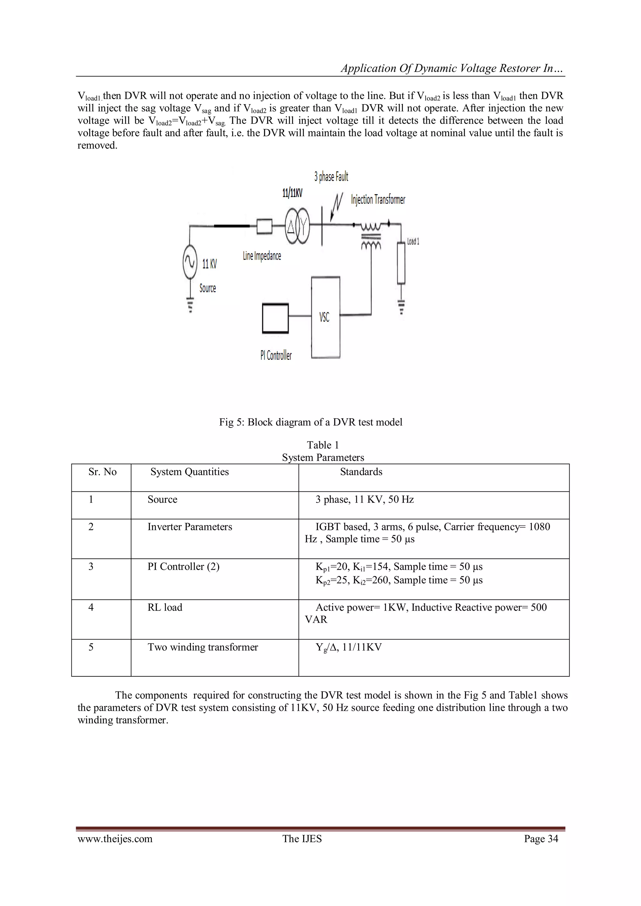
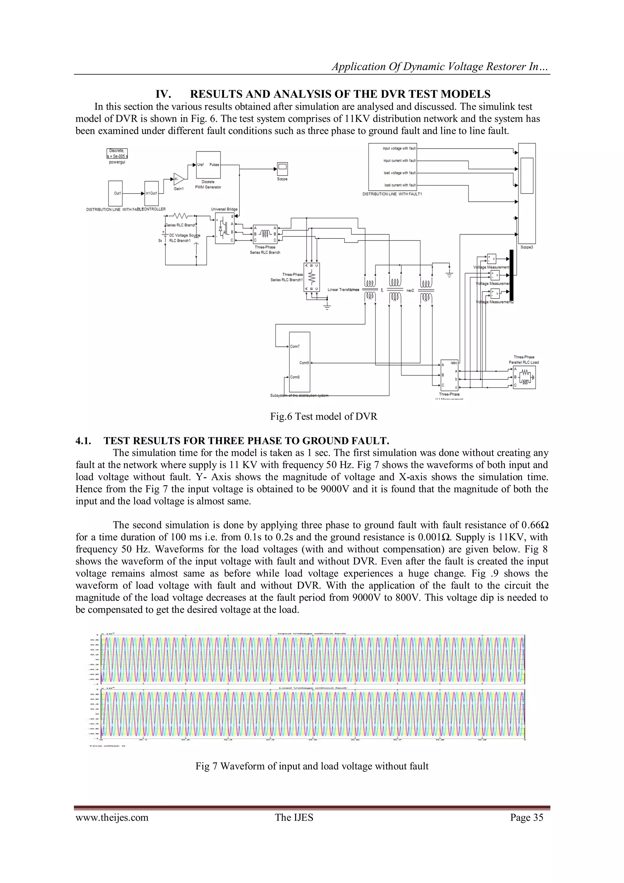
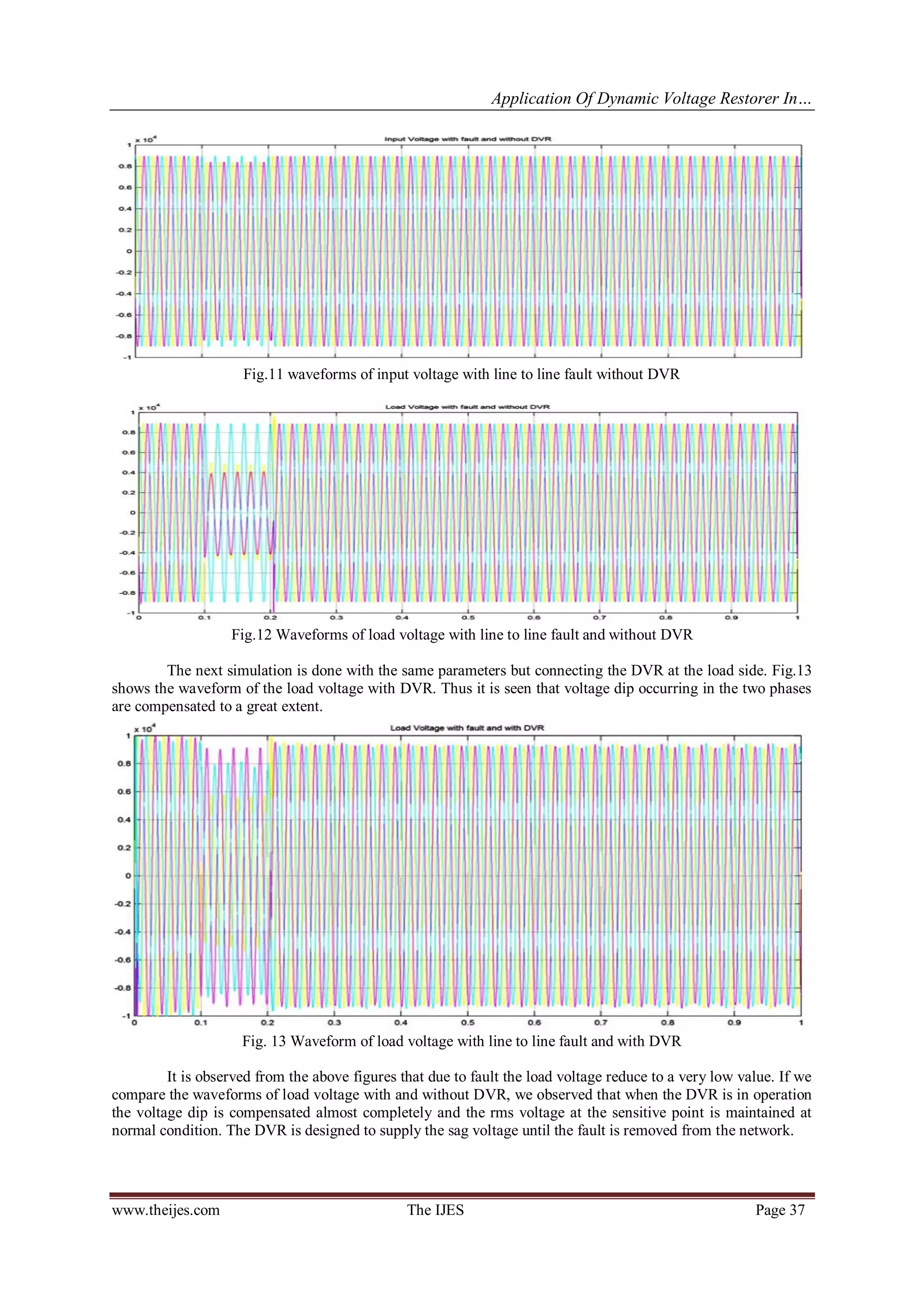
The document discusses a study on the application of Dynamic Voltage Restorer (DVR) in electrical distribution systems to compensate for voltage sags, which pose significant issues for industrial consumers. It presents modeling, analysis, and simulation results using MATLAB Simulink, demonstrating the effectiveness of DVR under various fault conditions, including three-phase and line-to-line faults. The study emphasizes the importance of enhancing power quality through custom power devices like DVR, which efficiently manages voltage disturbances and maintains nominal load voltage.
![The International Journal Of Engineering And Science (IJES)
||Volume||2 ||Issue|| 7 ||Pages|| 30-38||2013||
ISSN(e): 2319 – 1813 ISSN(p): 2319 – 1805
www.theijes.com The IJES Page 30
Application of Dynamic Voltage Restorer in Electrical
Distribution System for Voltage Sag Compensation
1,
Swapnali Hazarika , 2,
Swagata Singha Roy, 3,
Rahul Baishya , 4,
Smriti Dey
1,
Department of Electrical and Electronics, Don Bosco College of Engineering and Technology,
Guwahati,781017, Assam
2,
Department of Electrical and Electronics, Don Bosco College of Engineering and Technology, Guwahati,
781017, Assam
3,
Department of Electrical and Electronics, Don Bosco College of Engineering and Technology, Guwahati,
781017, Assam
4,
Faculty of Electrical and Electronics department, Don Bosco College of Engineering and Technology,
Guwahati, 781017, Assam
E-mail: mamunu.hazarika@gmail.com
--------------------------------------------------------ABSTRACT----------------------------------------------------
Power quality has become a major area of concern in present era due to the increase in modern sensitive and
sophisticated loads connected to the Distribution System. One of the major problems dealt in this paper is the
voltage sag which is very severe for the industrial customers as it can cause malfunctioning of several sensitive
electronic equipments. Dynamic Voltage Restorer (DVR) is a custom power device (CPD) that is connected in
series with the network to improve voltage disturbance in the electrical system. This paper presents modeling,
analysis and simulation of Dynamic Voltage Restorer (DVR) in MATLAB SIMULINK. This paper proposes PI
controller and discrete PWM generator for control purpose of DVR. Simulation results are also presented to
illustrate and understand the performance of DVR under various fault conditions such as three phase to ground,
line to line fault etc. The results showed clearly the performance of the DVR in mitigating voltage sags.
KEYWORDS: Custom Power Device (CPD), Dynamic Voltage Restorer (DVR), PI controller, Power Quality
Pulse Width Modulation (PWM), Voltage Sag
----------------------------------------------------------------------------------------------------------------------------------------
Date of Submission: 01 July 2013, Date of Publication: 15.July 2013
---------------------------------------------------------------------------------------------------------------------------------------
I. INTRODUCTION
The present-day electrical power system is AC i.e. electric power is generated, transmitted and
distributed in the form of alternating current [2]. When the power is generated it possesses certain electrical
properties that allow electrical system to function in their intended manner i.e. it can energizes all electrical
equipment equally and satisfactorily. But power travels long distances through wires. Due to various pieces of
equipments or due to any abnormal conditions in the network, the quality of the power changes and thus it
becomes less suitable for any further application. Voltage magnitude is one of the major factors that determine
the quality of electrical power [10]. Hence it is necessary to improve the quality of power before it is used to
energize any load. Though the transmission system and the distribution system are similar for man’s circulatory
system, in present scenario power quality directly related to distribution system. The reason behind is that
distribution system locates at the end of the power system and is directly connected to the customer. The
distribution system can be defined as that part of power system which distributes electrical power to the
consumer for utilization [2]. Earlier the prime focus for power system reliability was on generation and
transmission system but now a day’s distribution system receives more attention. Because most of the electrical
distribution network failures account for about 90% of the average customer interruptions and if any disturbance
occur in the distribution system a huge amount of financial losses may happen with the consequent loss of
productivity and competitiveness.
Some consumers require a level of power quality higher than the level provided by modern networks of
electricity, hence many efforts have been under taken to fulfill consumer requirement. Initially for the
improvement of the power quality and reliability of the system, Flexible AC Transmission System (FACTS)
devices like static synchronous compensator (STATCOM), static synchronous series compensator (SSSC),
interline power flow controller (IPFC), unified power flow controller (UPFC) etc. were used. FACTS devices
are generally designed for the transmission system. But now-a-days these devices are modified to be used in](https://image.slidesharecdn.com/d027203038-130813052655-phpapp02/75/The-International-Journal-of-Engineering-and-Science-The-IJES-1-2048.jpg)
![Application Of Dynamic Voltage Restorer In…
www.theijes.com The IJES Page 31
distribution system and named as Custom Power Devices. Some of the widely used custom power devices are
Distribution Static Synchronous Compensator (DSTATCOM), Dynamic Voltage Restorer (DVR), Active filter
(AF), Unified power quality conditioner (UPQC) [4].
With the help of these devices power quality problems are reduced to a great extent. DVR is one of the
most efficient and effective custom power devices due to its fast response, lower cost and smaller size [12].
Control Unit is the vital part of DVR and its main function is to detect the presence of voltage sags in the
electrical system and to calculate the required amount of compensating voltage. The controlling of DVR is done
by a Proportional Integral (PI) Controller and a PWM Generator. PI controller is a type of feedback controller
which operates the system to be controlled with a weighted sum of error. It generates the desired signal for the
PWM generator to trigger the PWM inverter. The Phase lock loop (PLL) and dq0 transformation are also the
basic components of DVR [7]. This paper, investigates the performance of DVR in improving the quality of
power under three phase fault and line to line fault. The theory related to DVR operation and its different parts
have been discussed in the next section. In section III Experimental details and simulation are discussed, and in
section IV Analysis of the test results are done.
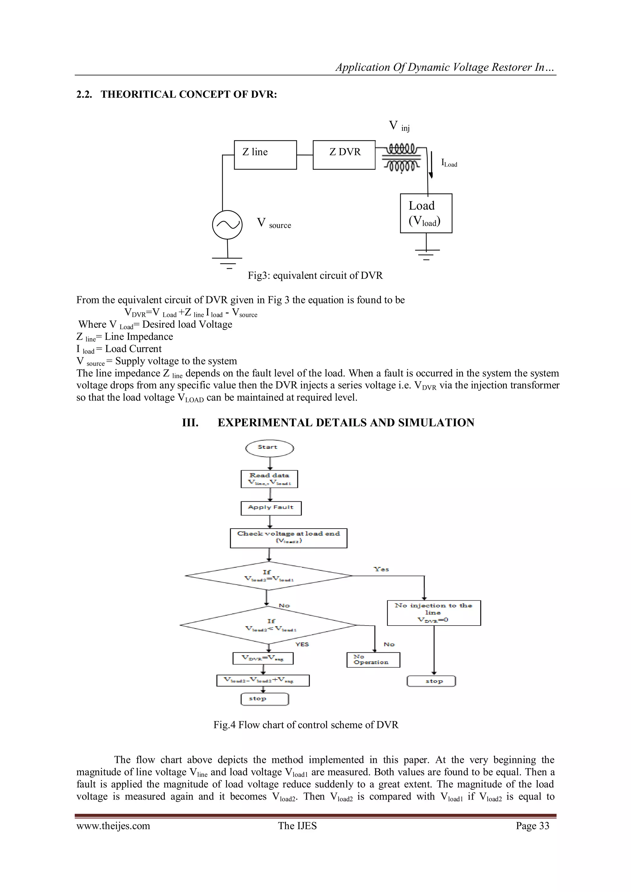
II. CONFIGURATION AND OPERATION OF DVR
Among the power quality problems like sag, swell, harmonic, transients etc, voltage sag i.e. sudden
voltage dip is the most severe disturbance in the power system, generally caused by faults. It last for duration
ranging from 3 cycles to 30 cycles [10]. Starting of large induction motors can also result in voltage sag as it
draws a large amount of current during starting. In order to mitigate this problem DVR is one of the efficient
and effective custom power devices. DVR injects voltage into the system in order to compensate the voltage
dip in the load side and maintains the load voltage at nominal magnitude.
DVR is a solid state power electronic switching device which is connected in series to the power system. It
comprises of the following components:
[1] Energy storage device
[2] Voltage source Inverter
[3] Injection transformer
[4] Control unit.
2.1. PRINCIPLE OF OPERATION
DVR is connected in between the supply and the load as shown in the Fig 1. The main function of the
DVR is to boost up the load side voltage so that load is free from any power disruption. Besides voltage sag
compensation DVR also carry out other functions such as line voltage harmonic compensation, reduction of
transients in voltage and fault current limitation.
Fig. 1 Operation principle of DVR
Supply Sensitive
Load
Energy
Storage
Voltage Source
Inverter
Voltage
sag
Injected voltage
Restored
voltageInjection
transformer](https://image.slidesharecdn.com/d027203038-130813052655-phpapp02/75/The-International-Journal-of-Engineering-and-Science-The-IJES-2-2048.jpg)
![Application Of Dynamic Voltage Restorer In…
www.theijes.com The IJES Page 32
[1] Energy storage device: The purpose of the energy source is to supply the necessary energy to the VSI
which will be converted to alternating quantity and fed to the injection transformer. Batteries are most
commonly used and the capacity of the battery determine the duration of the sag which can be
compensated by the DVR.
[1] Voltage Source Inverter (VSI): A voltage source inverter is a power electronic device consisting of a
switching device and a storage device such as battery. VSI can generate a sinusoidal voltage at any
required magnitude, phase and frequency. VSI is used to temporarily generate the part of the supply
voltage that is missing. IGBT is the newer compact switching device that is used with VSI for DVR
operation.
[2] Injection transformer: It consists of two side voltage one is high voltage side and low voltage side. The
high voltage side is normally connected in series with the distribution network while the power circuit
of the DVR is connected to the low voltage side [13]. The DVR transfer the voltage which is required
for the compensation from DC side of the inverter to the distribution network through the injection
transformer. In this paper three single phase transformers are connected instead of a single three phase
injection transformer. Each transformer is connected in series with each phase of the distribution
feeder to couple the VSI (at low voltage level) to the higher distribution level. The transformer also
helps in isolating the line from the DVR system.
[3] Control unit: A controller is used for proper operation of DVR system. DVR detects the presence of
voltage sags and operates to mitigate the voltage dip. Pulse Width Modulation (PWM) control
technique is applied for inverter switching so as to generate a three phase 50 Hz sinusoidal voltages at
the load terminals. The magnitude of load voltage is compared with reference voltage and if any
difference is there error signal will be generated as shown in the Fig.2. This error signal is the
actuating signal which drives the PI controller and the final output signal which is obtained controls
the pulses for the Inverter. PI controller is a feedback controller which controls the system depending
on the error signal. In PI controller technique the proportional response can be obtained by multiplying
the error with constant K p (proportional gain). The integral response is proportional to both the
magnitude of error and duration of error.
Fig.2 Schematic diagram of PI controller
In this study, the dq0 transformation or the Park’s transformation is used for voltage calculation where
the three phase stationary co-ordinate system is converted to the dq rotating quantity. The dq0 transformation
technique is used to give the information of the depth (d) and phase shift (q) of voltage sag with start and end
time. The V0, Vd and Vqare obtained as
V0 = (V a+ V b+ V c) = 0
V d = [Va sinωt + Vb sin(ωt- ) +Vc sin(ωt+ )]
V q = [Vacosωt + Vb cos (ωt- ) +Vc cos (ωt+ )]
After conversion of the three phase voltage V a, V b and V c into two constant voltages V d and V q the three
phase system is simplified for voltage calculations. And the system can be easily controlled. The input of the DVR
controller is taken from the output voltage measured by three-phase V-I measurement at load. This load voltage is
then transformed into the dq term. Then if there is any voltage sag then the error signal is generated from the
difference between the dq voltage and the reference voltage. The d reference is set to the rated voltage while the q
reference is always set to zero. The gains such as K p and Ki control the stability of the system. The output obtained
from the PI controller is then again transformed back to V abc before it is forwarded to the PWM generator.
The PWM generator will generate 6 pulses to trigger the PWM inverter.](https://image.slidesharecdn.com/d027203038-130813052655-phpapp02/75/The-International-Journal-of-Engineering-and-Science-The-IJES-3-2048.jpg)
![Application Of Dynamic Voltage Restorer In…
www.theijes.com The IJES Page 38
V. CONCLUSION
In this paper, the simulation of a DVR is done using MATLAB/SIMULINK software. Thus it became
easier to construct the large distribution network and analyse the various result for two different types of faults.
The controlling of DVR is done with the help of PI controller. The simulation results clearly showed the
performance of the DVR in mitigating the voltage sag due to different fault conditions in distribution systems.
DVR is one of the fast and effective custom power devices. DVR has shown the efficiency and effectiveness on
voltage sag compensation hence it makes DVR to be an interesting power quality improvement Device. This has
been proved through simulation and hardware implementation. From the analysis it is found that in case of a
three phase fault almost 91% of compensation is done and in line to line fault voltage compensation took place
for almost 44%.
Besides PI controllers, other controllers like fuzzy controllers and adaptive PI fuzzy controllers can
also be used in the DVR compensation technique. In future years, the multilevel concept of inverters will be a
prominent choice for power electronic systems mainly for medium voltage operation. Multilevel concept is the
best alternator to employ low-frequency based inverters with low output voltage distortion.
VI. ACKNOWLEDGEMENT
This work would not have been possible without the encouragement and able guidance of our
supervisor, Ms. Smriti Dey, Department of Electrical and Electronics, Don Bosco College of Engineering and
Technology, Guwahati for her valuable suggestions and continuous motivation. We would also like to thank Dr.
Shakuntala Laskar (HOD) and to our project coordinator Mr. Bikramjit Goswami, Assistant professor, DBCET,
Guwahati who has been a constant source of inspiration throughout this work.
REFERENCES
[1] C. Sankaran “Power Quality”, CRC Press 2002.
[2] V.K Mehta, Rohit Mehta, Principle of Power System ( revised edition, pp 300-309)
[3] N.G. Hingorani, Flexible AC Transmission", IEEE Spectrum, vol. 30, pp. 40-44, 1993.
[4] N.G. Hingorani and L Gyugyi, “Understanding FACTS – Concepts and Technology OF Flexible AC Transmission Systems”,
IEEE Press, New York, 2000.
[5] N.G. Hingorani, “Introducing Custom Power", IEEE Spectrum, vol. 32, pp. 41- 48, 1995
[6] Guide for Application of Power Electronics for Power Quality Improvement on Distribution Systems Rated 1 kV to 38 kV,
IEEE P1409 Distribution Custom Power Task Force, 2003.
[7] R. H. Salimin, M.S. A. Rahim, “Simulation Analysis of DVR performance for voltage sag mitigation”, the 5th international
power Engineering and Optimization Conference (PEOCO2011), 2011
[8] Michael D. Stump, Gerald J. Keane “The role, of custom power products in enhancing power quality at industrial facilities”,
Energy Management and Power Delivery, vol. 2, pp.507-517, International Conference 1998
[9] D. Daniel Sabin, Senior Member, IEEE, and Ambra Sannino, IEEE “A Summary of the Draft IEEE P1409 Custom Power
Application Guide” Transmission and Distribution Conference and Exposition, IEEE PES, vol. 3, pp. 931-936, 2003.
[10] M. H. Haque, "Compensation of Distribution System Voltage Sag by DVR and DSTATCOM", IEEE Porto Power Tech
Conference, vol. 1, 2002.
[11] Yash Pal, A. Swarup, Senior Member, IEEE, and Bhim Singh, Senior Member, IEEE “A Review of Compensating Type Custom
Power Devices for Power Quality Improvement” IEEE Power India Conference, pp. 1-8, 2008.
[12] Bingsen Wang, Giri Venkataramanan and Mahesh Illindala, “Operation and Control of a Dynamic
[13] Voltage Restorer Using. Transformer Coupled H-Bridge Converters”, IEEE transactions on Power electronics, vol. 21,
pp. 1053- 1061, July06
[14] Rosli Omar, N.A. Rahim and Marizan Slaiman, “Dynamic Voltage restorer Application for Power
[15] Quality improvement in Electrical Distribution System” Australian Journal of Basic and applied Sciences , pp 379-396,
2011
[16] H.P. Tiwari and Sunil Kumar Gupta “Dynamic Voltage Restorer against Voltage Sag” International Journal of Innovation,
Management and Technology vol. 1, no. 3, pp. 232-237, 2010.](https://image.slidesharecdn.com/d027203038-130813052655-phpapp02/75/The-International-Journal-of-Engineering-and-Science-The-IJES-9-2048.jpg)


![Coded Agents – with UiPath SDK + LangGraph [Virtual Hands-on Workshop]](https://cdn.slidesharecdn.com/ss_thumbnails/codedagentsdeck-251215155422-5497c599-thumbnail.jpg?width=640&height=640&fit=bounds)


