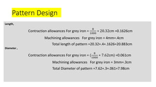
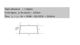
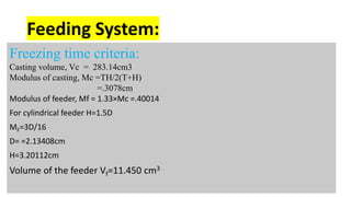
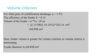
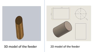
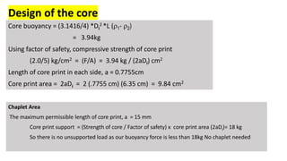
Cylindrical liner
Presented by
Hridoy Saha
1611042
Design project
MME-346 Foundry Engineering Sessional
Pattern Design
Length,
Contraction allowances For grey iron =
8
1000
∗ 20.32cm =0.1626cm
Machining allowances For grey iron = 4mm=.4cm
Total length of pattern =20.32+.4+.1626=20.883cm
Diameter ,
Contraction allowances For grey iron = (
8
1000
∗ 7.62cm) =0.061cm
Machining allowances For grey iron = 3mm=.3cm
Total Diameter of pattern =7.62+.3+.061=7.98cm
Taper allowance = 1 degree
In the figure, a= Do tan(1) = .1253cm
Thus, L2 = L1 – 2a = 20.88 – 2(0.1253) = 20.62cm
3D model of the pattern 2D model of the pattern
Feeding System:
Freezing time criteria:
Casting volume, Vc = 283.14cm3
Modulus of casting, Mc =TH/2(T+H)
=.3078cm
Modulus of feeder, Mf = 1.33×Mc =.40014
For cylindrical feeder H=1.5D
MF=3D/16
D= =2.13408cm
H=3.20112cm
Volume of the feeder Vf=11.450 cm3
Volume criterion
For white pure Al solidification shrinkage, α = 1.5%
The efficiency of the feeder, € = 0.14
Volume of the feeder = α *Vc / (€-α)
= {(1.5/100)/(.14-.015)}*283.14 cm3
=33.978 cm3
Here, feeder volume is greater for volume criterion so volume criteria is
dominating.
Feeder diameter Vf=33.978 cm3
3D model of the feeder 2D model of the feeder
The gating design
The volume of the cast piece= 283.14 cm3
The feeder volume from the volume criterion is, 33.978 cm3
Total volume of the cast= 283.14+33.978 cm3= 317.118 cm3
the mass required for the cast is= 2.28324 kg
Considering extra 40 % weight to allow shrinkage the modified weight will
be= 3.1965 kg
Pouring time:
For the calculation of pouring time of cast iron, the equation is, pouring time, t= SW.5
For the wall thickness of around 6.3mm the co-efficient S= 1.85
Then, the pouring time, t=3.3076 sec
Pouring rate
The pouring rate will be = weight/ pouring time= 3.1965/3.3076= 0.9664 kgs-1
To get the accurate pouring time the correction factor has to be considered.
Here, corrected pouring rate, Ra= R/kf = 1.07382 kg/sec
Choke area calculation:
Hence the choke area will be, 𝐴 𝑐 =
𝑊
𝜌𝑡𝑐 2𝑔ℎ 𝑝
= 92.827 mm2
From the basic assumption, the choke area = the sprue bottom area
= 10.87 mm φ
So, sprue top area, (considering the allowance of 15%)
A1=177.41 mm2= 15.02 mm φ
So, considering the gating ratio of 1:2:4
Runner area = 2* sprue bottom area= 92.827*2=185.654 mm2 = 15.3747 mm φ
Gate area= 2* runner area = 185.654*2 mm2 = 371.308 mm2
Considering the inclusion of 2 gates,
Area per gate= total gate area/2= 371.308/2= 185.654 mm2
Gate dimensions= 15.3747 mm φ
Sprue runner gate
Sprue in 3D
Sprue in 2D
Runner in 3D
Runner in 2D
Design of the core
Core buoyancy = (3.1416/4) *Di
2 *L (r1- r2)
= 3.94kg
Using factor of safety, compressive strength of core print
(2.0/5) kg/cm2 = (F/A) = 3.94 kg / (2aDi) cm2
Length of core print in each side, a = 0.7755cm
Core print area = 2aDi = 2 (.7755 cm) (6.35 cm) = 9.84 cm2
Chaplet Area
The maximum permissible length of core print, a = 15 mm
Core print support = (Strength of core / Factor of safety) x core print area (2aDi)= 18 kg
So there is no unsupported load as our buoyancy force is less than 18kg No chaplet needed
Core in 3D
Core in 2D
Core in a pattern
The final design
Cylindrical liner

Cylindrical liner

  • 1.
    Cylindrical liner Presented by HridoySaha 1611042 Design project MME-346 Foundry Engineering Sessional
  • 3.
    Pattern Design Length, Contraction allowancesFor grey iron = 8 1000 ∗ 20.32cm =0.1626cm Machining allowances For grey iron = 4mm=.4cm Total length of pattern =20.32+.4+.1626=20.883cm Diameter , Contraction allowances For grey iron = ( 8 1000 ∗ 7.62cm) =0.061cm Machining allowances For grey iron = 3mm=.3cm Total Diameter of pattern =7.62+.3+.061=7.98cm
  • 4.
    Taper allowance =1 degree In the figure, a= Do tan(1) = .1253cm Thus, L2 = L1 – 2a = 20.88 – 2(0.1253) = 20.62cm
  • 5.
    3D model ofthe pattern 2D model of the pattern
  • 6.
    Feeding System: Freezing timecriteria: Casting volume, Vc = 283.14cm3 Modulus of casting, Mc =TH/2(T+H) =.3078cm Modulus of feeder, Mf = 1.33×Mc =.40014 For cylindrical feeder H=1.5D MF=3D/16 D= =2.13408cm H=3.20112cm Volume of the feeder Vf=11.450 cm3
  • 7.
    Volume criterion For whitepure Al solidification shrinkage, α = 1.5% The efficiency of the feeder, € = 0.14 Volume of the feeder = α *Vc / (€-α) = {(1.5/100)/(.14-.015)}*283.14 cm3 =33.978 cm3 Here, feeder volume is greater for volume criterion so volume criteria is dominating. Feeder diameter Vf=33.978 cm3
  • 8.
    3D model ofthe feeder 2D model of the feeder
  • 9.
    The gating design Thevolume of the cast piece= 283.14 cm3 The feeder volume from the volume criterion is, 33.978 cm3 Total volume of the cast= 283.14+33.978 cm3= 317.118 cm3 the mass required for the cast is= 2.28324 kg Considering extra 40 % weight to allow shrinkage the modified weight will be= 3.1965 kg
  • 10.
    Pouring time: For thecalculation of pouring time of cast iron, the equation is, pouring time, t= SW.5 For the wall thickness of around 6.3mm the co-efficient S= 1.85 Then, the pouring time, t=3.3076 sec Pouring rate The pouring rate will be = weight/ pouring time= 3.1965/3.3076= 0.9664 kgs-1 To get the accurate pouring time the correction factor has to be considered. Here, corrected pouring rate, Ra= R/kf = 1.07382 kg/sec Choke area calculation: Hence the choke area will be, 𝐴 𝑐 = 𝑊 𝜌𝑡𝑐 2𝑔ℎ 𝑝 = 92.827 mm2
  • 11.
    From the basicassumption, the choke area = the sprue bottom area = 10.87 mm φ So, sprue top area, (considering the allowance of 15%) A1=177.41 mm2= 15.02 mm φ So, considering the gating ratio of 1:2:4 Runner area = 2* sprue bottom area= 92.827*2=185.654 mm2 = 15.3747 mm φ Gate area= 2* runner area = 185.654*2 mm2 = 371.308 mm2 Considering the inclusion of 2 gates, Area per gate= total gate area/2= 371.308/2= 185.654 mm2 Gate dimensions= 15.3747 mm φ Sprue runner gate
  • 12.
    Sprue in 3D Spruein 2D Runner in 3D Runner in 2D
  • 13.
    Design of thecore Core buoyancy = (3.1416/4) *Di 2 *L (r1- r2) = 3.94kg Using factor of safety, compressive strength of core print (2.0/5) kg/cm2 = (F/A) = 3.94 kg / (2aDi) cm2 Length of core print in each side, a = 0.7755cm Core print area = 2aDi = 2 (.7755 cm) (6.35 cm) = 9.84 cm2 Chaplet Area The maximum permissible length of core print, a = 15 mm Core print support = (Strength of core / Factor of safety) x core print area (2aDi)= 18 kg So there is no unsupported load as our buoyancy force is less than 18kg No chaplet needed
  • 14.
    Core in 3D Corein 2D Core in a pattern
  • 15.