•
0 likes•83 views
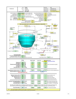
This document provides design specifications for equipment numbers 02-01-SU-050 & 051. It details parameters like solids flow rate, required retention time, densities, and sump dimensions. Key specifications include a solids flow rate of 4360 t/h, minimum retention time of 60 seconds, and minimum cone angle of 55 degrees. Detailed dimensions are provided for the sump cylinder and cone sections as well as pump suction details. Mass and volume calculations are presented for design validation.
Report
Share
Report
Share
Download to read offline
Recommended
Section 7 multistage separation processes
This document provides an example problem to design a distillation column for separating acetone from an aqueous waste stream. The following steps are included:
1) Performing a material balance to calculate unknown flow rates.
2) Estimating the actual number of plates needed based on an overall efficiency of 60%.
3) Calculating the column diameter by determining vapor velocities and flow rates.
4) Determining the liquid flow pattern will be normal flow.
5) Performing a complete plate design which includes checking for weeping by calculating minimum vapor and liquid velocities and heights.
Blower
The document calculates various airflow parameters of a blower: the airflow rate is 0.0174 cubic meters per second with an impeller diameter of 0.1 meters. Using the airflow rate and impeller area, the airflow velocity is calculated as 2.2154 meters per second. This velocity is then used to find the velocity pressure as 0.2502 meters and the total pressure required by the blower as 0.2571 Watts, accounting for the blower height of 1 meter above the surface.
Diseño de tanques
This document contains calculations for determining the required thickness of a cylindrical pressure vessel based on ASME code requirements. It provides the dimensions, material properties, and calculations for a cylindrical vessel with an outside diameter of 108.661 inches, wall thickness of 0.709 inches, and length of 720 inches made of SA-516 Grade 70 steel. The calculations determine the required minimum thickness, maximum internal pressure, and check that the actual thickness and pressure are acceptable according to the ASME code requirements for a cylindrical pressure vessel.
Cylindrical liner
This is a casting design of a cylindrical liner. the design includes pattern making, feeder design, gate, and sprue runner design at last core design.
Design of gating system
This document discusses different types of gating systems used in metal casting and their design considerations. It describes top gates, bottom gates, parting line gates, and step gates. It then covers gating ratios for pressurized and unpressurized systems. Pressurized systems use a 1:2:1 ratio of sprue to runner to ingate areas to control flow. Unpressurized systems use a 1:2:2 ratio with the choke controlling flow. It provides examples of questions on gating systems and their components.
Hm international mold flow standard
The document outlines the order and contents of a mold flow report for a plastic part. Key results include:
- Fill time of 0.9904 seconds
- Maximum deflection of 0.371mm in the Z direction
- Maximum shear rate and stress of 95621 1/s and 4.03MPa at the gate
- Suggestions to reduce weld lines and uniform shrinkage include increasing melt temperature and injection pressure.
Results phe works 2.0 2
https://www.slideshare.net/UsamaKhan106/a-noniterative-way-for-preliminary-designing-plate-frame-exchanger
W
The document describes the production of biobutanol through fermentation and downstream processing. Key points:
- Biobutanol is produced through a fermentation process in a large reactor vessel. The document sizes the reactor to hold 50,000L based on standard length to diameter ratios.
- The fermented biobutanol is then stored in a holding tank before further processing. The document designs a holding tank 55,555L in volume and 34m in diameter and 68m in length to store the biobutanol.
- The document also includes mechanical design details for the fermenter, holding tank, heat exchanger and distillation column used in downstream processing of the biobutanol
Detritor Design
This document provides design details for a mechanical detritor tank for grit removal from wastewater. The key details are:
- The average flow is 60 MLD with a peak factor of 2.25, resulting in a peak flow of 135 MLD.
- The design calls for 2 detritor tanks each with a volume of 20.8333 cubic meters and a liquid depth of 0.6 meters to accommodate a scrapper mechanism.
- Key design considerations and calculations include the grit size, settling velocity, surface overflow rate, detention time, horizontal flow velocity, and grit storage requirements.
Grit Design
The document provides design details for a manual grit chamber, including:
1) Dimensions are calculated based on an average flow of 3 MLD and peak flow of 7.5 MLD.
2) Settling velocity and reynolds number calculations are used to determine the diameter is 0.00015 m.
3) Based on an efficiency of 75% and other parameters, the overflow rate is calculated as 1010.3260330988 m3/m2/day.
90 mm pipe 45 deg
1. This document analyzes the thrust block parameters for a 90mm diameter pipe bent at 45 degrees. It calculates thrust values, soil and concrete weights, buoyancy forces, and passive soil resistance.
2. Stability is evaluated for overturning, sliding, and buoyancy at the design pressure of 450 kN/m2 and hydrostatic test pressure of 675 kN/m2. Factors of safety are above 1.5, indicating the thrust block design is safe.
3. The key parameters of the 90mm diameter pipe bent at 45 degrees are summarized, including the design and hydrostatic test pressures used in the stability evaluations.
Diesel Production: Equipments Design
Process & Mechanical Design of Reactor, Distillation column & heat exchanger. Gasket, nozzle & quench coil design.
Economic pipe size
To determine the optimum pipe diameter, you should go make the comparative analysis to determine the most optimum pipe size which reflects the most economic option.
This example is for illustration the importance of the the comparative analysis.
Note: According to ASME, pipe with 5 in diameter is not standard, but i selected it in the example for illustration only.
Calculo tramo tipico
This document discusses calculating hydraulic parameters for a typical pipe section using Manning's equation. It provides input values for pipe diameter, depth, slope, and Manning's n roughness coefficient. The computed results include flow rate, area, wetted area, wetted perimeter, perimeter, velocity, hydraulic radius, full flow rate, and full flow velocity.
Diethyl Ether (DEE): Equipments Design
Design of Primary & auxiliary equipment of Diethyl ether production plant. Process & mechanical design of Reactor, Heat exchanger, Distillation column.
Rectangular clarifier
The document describes the design of internals for a rectangular clarifier. It includes:
- Key internals like inlet baffles, drive units, effluent weirs, scum troughs, and sludge hoppers.
- Design parameters calculated for a clarifier treating 3,000 cubic meters of wastewater per day, including flow velocity, Reynolds number, detention time, and weir loading rate.
- Design of V-notch weirs based on a calculated flow rate, with a notch height of 1.2 cm and width of 7.2 cm, requiring 605 notches around the perimeter.
- Recommended slope range of 1:100 to 1
Concept of save max boiler design (1)
This document discusses the design of a Save Max boiler. It covers the customer inputs needed, the design procedure which involves determining the heat surface area and preparing the tube plate. Key design parameters that are calculated include tube pitch and thickness, furnace and wrapper drum plate thickness, stayed surface thickness, and shell thickness according to IBR regulations. Tube plate development must consider tube outer diameter, pitch, heat surface area, and gusset placement. Finally, detail drawings are prepared to communicate the design to production.
LPG-injectors RAIL IG1
This document provides technical specifications for gas injectors, including their operating temperature range from -40°C to +120°C, compatibility with LPG and CNG gases, and power handling capabilities up to 45HP/cylinder for LPG and 40HP/cylinder for CNG. It also lists injection timing specifications measured at 12V and 1 bar Δp at 25°C, with opening times of 3.3ms and closing times of 2.8ms. Cold start requirements and coil specifications like resistance, peak current time, and rated voltage are also provided.
Lecture 6 Numerical (unit 3)
1) The document provides two examples of designing journal bearings for centrifugal pumps. The first example calculates the dimensions, operating characteristics, and heat generation of a journal bearing. It determines artificial cooling is required.
2) The second example calculates the artificial cooling required and mass of lubricating oil needed to limit temperature rise to 10°C for a journal bearing operating at 1.4 N/mm^2 pressure and 900 rpm. It determines values for heat generation, dissipation, and lubricating oil mass.
3) Throughout, the document refers to design data and equations from the referenced machine design textbook to analyze and size the journal bearings.
Solucionario p2 conc. avanzado
This document summarizes the design of a combined foundation (zapata combinada) including:
1) Calculating the required foundation area and length based on loads and soil properties
2) Analyzing three cases of load combinations and selecting the critical case
3) Determining design forces and checking capacity against nominal strength
4) Detailing the longitudinal reinforcement for two columns
FINAL DESIGN-OF-ABSORPTION-COLUMN
The document summarizes the design of an absorption column to remove SO2 from an air stream. It involves selecting water as the solvent, 1.5 inch Raschig rings as the packing material, calculating the minimum liquid flow rate of 6480.0866 kg/h, tower diameter of 1.106 m, and tower height of 3.88 m based on the material and energy balances. The column will treat 40,000 ft3/h of air containing 20% SO2 and recover 96% of the SO2 using a liquid flow rate 30% higher than minimum.
Foundation grouting2
This document discusses the construction and completion of the Batu Hampar Dam and associated works in Malaysia. It describes the following key points in 3 sentences:
The document outlines the grouting work done to seal seepages, reduce dam foundation leakage, and strengthen the foundation. It discusses the steps of test drilling, water testing holes, and grouting based on lugeon values. Details are provided on grout mix designs, performing grouting on site, and terminating grouting when absorption is less than 2 liters per minute or grout leaks are observed.
Condensation
- Condensation occurs when a vapor is cooled and changes phase to a liquid. This happens in power plants, oil refineries, and desalination plants.
- Condensation can occur through either film condensation or dropwise condensation. Film condensation involves a liquid film forming on the surface, while dropwise condensation involves discrete liquid droplets.
- Dropwise condensation is more efficient with higher heat transfer rates, but is difficult to maintain as the droplet-promoting coating washes off over time. Most condensers are designed for the more conservative film condensation process.
Margen izquierdo ok
The document contains laboratory test results and calculations to determine the bearing capacity of soil. It includes soil properties like cohesion, internal friction angle, unit weight measured in the lab and field. It then shows calculations for ultimate bearing capacity and allowable bearing capacity of square foundations using Terzaghi's method for various depths and widths. The results are presented in tables with recommended allowable values between 1-2 kg/cm2 depending on the foundation size.
Final presentation
The presentation was on final year design project, "Production of LPG from NGLs and condensate". It includes process selection, establishing a flow diagram for the selected process, the sizing of main equipments, detailed design of four Major equipments along with P & ID control for the systems and finally the economic evaluation was conducted to check the feasibility of the process. The final product composition of LPG was simulated using Aspen HYSYS and found to be 49% Propane and 21% butane.
Ship design project & presentation 3
This document provides design details for an oil tanker ship with the following specifications:
- Ship Type: Oil Tanker
- DWT: 2900 tonnes
- Route: Chittagong to Dhaka
- Speed: 10 knots
It includes the principal particulars, general arrangement, lines plan, offset table, and designs for the rudder, steering gear, resistance and power calculations, engine and gearbox selection, engine foundation, propeller shaft, and propeller. The summaries provide key technical specifications and selections for the main ship components to meet the design objectives.
Tugas 3 Contoh Perhitungan Pompa.pptx
This document discusses the calculation of ballast pump installation for a ship. It provides ship specifications and calculates the ship's displacement and weight of ballast water needed. It then calculates the required capacity, diameter of the main ballast pipe, and head losses in the suction and discharge pipes. Finally, it concludes the total head losses required and provides the specifications for the main ballast pump and general service pump.
Isolated Footing
The document summarizes the design of an isolated square footing to support a 400x400mm reinforced concrete column with a vertical load of 50kN. It describes the 7 steps taken: 1) sizing the footing, 2) checking two-way shear, 3) designing flexure reinforcement, 4) checking one-way shear, 5) checking development length, 6) checking bearing stress, 7) distributing reinforcement. The final footing dimensions are 2x2m with a depth of 250mm. 12mm diameter bars are provided at 300mm spacing with 50mm clear cover and 740mm development length to satisfy design requirements.
All hvac calculation
This document contains calculations and information for sizing HVAC systems and components. It includes psychrometric calculations to determine cooling and heating loads based on outdoor conditions, building envelope properties, internal gains, and desired indoor conditions. Spreadsheets provide templates for calculating duct sizing, pressure loss, fan sizing, and air leakage testing. Preliminary pipe sizing and module temperature calculations are also referenced. The document contains information on HVAC system design and sizing.
Cálculos para bombas del sistema de agua de la planta
This document outlines calculations for pumps in a plant water system. It determines that the total plant water consumption is 5 cubic meters per hour based on overhead tank capacities. It then calculates that the pump capacity should be 5 cubic meters per hour to meet this demand. The pump head is calculated based on losses in the suction and discharge pipes, which total to 21.055 meters. With a 10% margin, the selected pump head is 25 meters. The results are that two pumps are needed, each with a capacity of 5 cubic meters per hour and a head of 25 meters.
More Related Content
What's hot
Detritor Design
This document provides design details for a mechanical detritor tank for grit removal from wastewater. The key details are:
- The average flow is 60 MLD with a peak factor of 2.25, resulting in a peak flow of 135 MLD.
- The design calls for 2 detritor tanks each with a volume of 20.8333 cubic meters and a liquid depth of 0.6 meters to accommodate a scrapper mechanism.
- Key design considerations and calculations include the grit size, settling velocity, surface overflow rate, detention time, horizontal flow velocity, and grit storage requirements.
Grit Design
The document provides design details for a manual grit chamber, including:
1) Dimensions are calculated based on an average flow of 3 MLD and peak flow of 7.5 MLD.
2) Settling velocity and reynolds number calculations are used to determine the diameter is 0.00015 m.
3) Based on an efficiency of 75% and other parameters, the overflow rate is calculated as 1010.3260330988 m3/m2/day.
90 mm pipe 45 deg
1. This document analyzes the thrust block parameters for a 90mm diameter pipe bent at 45 degrees. It calculates thrust values, soil and concrete weights, buoyancy forces, and passive soil resistance.
2. Stability is evaluated for overturning, sliding, and buoyancy at the design pressure of 450 kN/m2 and hydrostatic test pressure of 675 kN/m2. Factors of safety are above 1.5, indicating the thrust block design is safe.
3. The key parameters of the 90mm diameter pipe bent at 45 degrees are summarized, including the design and hydrostatic test pressures used in the stability evaluations.
Diesel Production: Equipments Design
Process & Mechanical Design of Reactor, Distillation column & heat exchanger. Gasket, nozzle & quench coil design.
Economic pipe size
To determine the optimum pipe diameter, you should go make the comparative analysis to determine the most optimum pipe size which reflects the most economic option.
This example is for illustration the importance of the the comparative analysis.
Note: According to ASME, pipe with 5 in diameter is not standard, but i selected it in the example for illustration only.
Calculo tramo tipico
This document discusses calculating hydraulic parameters for a typical pipe section using Manning's equation. It provides input values for pipe diameter, depth, slope, and Manning's n roughness coefficient. The computed results include flow rate, area, wetted area, wetted perimeter, perimeter, velocity, hydraulic radius, full flow rate, and full flow velocity.
Diethyl Ether (DEE): Equipments Design
Design of Primary & auxiliary equipment of Diethyl ether production plant. Process & mechanical design of Reactor, Heat exchanger, Distillation column.
Rectangular clarifier
The document describes the design of internals for a rectangular clarifier. It includes:
- Key internals like inlet baffles, drive units, effluent weirs, scum troughs, and sludge hoppers.
- Design parameters calculated for a clarifier treating 3,000 cubic meters of wastewater per day, including flow velocity, Reynolds number, detention time, and weir loading rate.
- Design of V-notch weirs based on a calculated flow rate, with a notch height of 1.2 cm and width of 7.2 cm, requiring 605 notches around the perimeter.
- Recommended slope range of 1:100 to 1
Concept of save max boiler design (1)
This document discusses the design of a Save Max boiler. It covers the customer inputs needed, the design procedure which involves determining the heat surface area and preparing the tube plate. Key design parameters that are calculated include tube pitch and thickness, furnace and wrapper drum plate thickness, stayed surface thickness, and shell thickness according to IBR regulations. Tube plate development must consider tube outer diameter, pitch, heat surface area, and gusset placement. Finally, detail drawings are prepared to communicate the design to production.
LPG-injectors RAIL IG1
This document provides technical specifications for gas injectors, including their operating temperature range from -40°C to +120°C, compatibility with LPG and CNG gases, and power handling capabilities up to 45HP/cylinder for LPG and 40HP/cylinder for CNG. It also lists injection timing specifications measured at 12V and 1 bar Δp at 25°C, with opening times of 3.3ms and closing times of 2.8ms. Cold start requirements and coil specifications like resistance, peak current time, and rated voltage are also provided.
Lecture 6 Numerical (unit 3)
1) The document provides two examples of designing journal bearings for centrifugal pumps. The first example calculates the dimensions, operating characteristics, and heat generation of a journal bearing. It determines artificial cooling is required.
2) The second example calculates the artificial cooling required and mass of lubricating oil needed to limit temperature rise to 10°C for a journal bearing operating at 1.4 N/mm^2 pressure and 900 rpm. It determines values for heat generation, dissipation, and lubricating oil mass.
3) Throughout, the document refers to design data and equations from the referenced machine design textbook to analyze and size the journal bearings.
Solucionario p2 conc. avanzado
This document summarizes the design of a combined foundation (zapata combinada) including:
1) Calculating the required foundation area and length based on loads and soil properties
2) Analyzing three cases of load combinations and selecting the critical case
3) Determining design forces and checking capacity against nominal strength
4) Detailing the longitudinal reinforcement for two columns
FINAL DESIGN-OF-ABSORPTION-COLUMN
The document summarizes the design of an absorption column to remove SO2 from an air stream. It involves selecting water as the solvent, 1.5 inch Raschig rings as the packing material, calculating the minimum liquid flow rate of 6480.0866 kg/h, tower diameter of 1.106 m, and tower height of 3.88 m based on the material and energy balances. The column will treat 40,000 ft3/h of air containing 20% SO2 and recover 96% of the SO2 using a liquid flow rate 30% higher than minimum.
Foundation grouting2
This document discusses the construction and completion of the Batu Hampar Dam and associated works in Malaysia. It describes the following key points in 3 sentences:
The document outlines the grouting work done to seal seepages, reduce dam foundation leakage, and strengthen the foundation. It discusses the steps of test drilling, water testing holes, and grouting based on lugeon values. Details are provided on grout mix designs, performing grouting on site, and terminating grouting when absorption is less than 2 liters per minute or grout leaks are observed.
Condensation
- Condensation occurs when a vapor is cooled and changes phase to a liquid. This happens in power plants, oil refineries, and desalination plants.
- Condensation can occur through either film condensation or dropwise condensation. Film condensation involves a liquid film forming on the surface, while dropwise condensation involves discrete liquid droplets.
- Dropwise condensation is more efficient with higher heat transfer rates, but is difficult to maintain as the droplet-promoting coating washes off over time. Most condensers are designed for the more conservative film condensation process.
Margen izquierdo ok
The document contains laboratory test results and calculations to determine the bearing capacity of soil. It includes soil properties like cohesion, internal friction angle, unit weight measured in the lab and field. It then shows calculations for ultimate bearing capacity and allowable bearing capacity of square foundations using Terzaghi's method for various depths and widths. The results are presented in tables with recommended allowable values between 1-2 kg/cm2 depending on the foundation size.
What's hot (16)
Similar to LinkedIn
Final presentation
The presentation was on final year design project, "Production of LPG from NGLs and condensate". It includes process selection, establishing a flow diagram for the selected process, the sizing of main equipments, detailed design of four Major equipments along with P & ID control for the systems and finally the economic evaluation was conducted to check the feasibility of the process. The final product composition of LPG was simulated using Aspen HYSYS and found to be 49% Propane and 21% butane.
Ship design project & presentation 3
This document provides design details for an oil tanker ship with the following specifications:
- Ship Type: Oil Tanker
- DWT: 2900 tonnes
- Route: Chittagong to Dhaka
- Speed: 10 knots
It includes the principal particulars, general arrangement, lines plan, offset table, and designs for the rudder, steering gear, resistance and power calculations, engine and gearbox selection, engine foundation, propeller shaft, and propeller. The summaries provide key technical specifications and selections for the main ship components to meet the design objectives.
Tugas 3 Contoh Perhitungan Pompa.pptx
This document discusses the calculation of ballast pump installation for a ship. It provides ship specifications and calculates the ship's displacement and weight of ballast water needed. It then calculates the required capacity, diameter of the main ballast pipe, and head losses in the suction and discharge pipes. Finally, it concludes the total head losses required and provides the specifications for the main ballast pump and general service pump.
Isolated Footing
The document summarizes the design of an isolated square footing to support a 400x400mm reinforced concrete column with a vertical load of 50kN. It describes the 7 steps taken: 1) sizing the footing, 2) checking two-way shear, 3) designing flexure reinforcement, 4) checking one-way shear, 5) checking development length, 6) checking bearing stress, 7) distributing reinforcement. The final footing dimensions are 2x2m with a depth of 250mm. 12mm diameter bars are provided at 300mm spacing with 50mm clear cover and 740mm development length to satisfy design requirements.
All hvac calculation
This document contains calculations and information for sizing HVAC systems and components. It includes psychrometric calculations to determine cooling and heating loads based on outdoor conditions, building envelope properties, internal gains, and desired indoor conditions. Spreadsheets provide templates for calculating duct sizing, pressure loss, fan sizing, and air leakage testing. Preliminary pipe sizing and module temperature calculations are also referenced. The document contains information on HVAC system design and sizing.
Cálculos para bombas del sistema de agua de la planta
This document outlines calculations for pumps in a plant water system. It determines that the total plant water consumption is 5 cubic meters per hour based on overhead tank capacities. It then calculates that the pump capacity should be 5 cubic meters per hour to meet this demand. The pump head is calculated based on losses in the suction and discharge pipes, which total to 21.055 meters. With a 10% margin, the selected pump head is 25 meters. The results are that two pumps are needed, each with a capacity of 5 cubic meters per hour and a head of 25 meters.
project ppt
The document summarizes the design of a 30,000 MTPA maleic anhydride production plant in India. It includes:
1) An introduction describing the importance of maleic anhydride and the aim to design a cost-effective plant using mixed butane as a feedstock.
2) Details of the major process units - feedstock pretreatment, synthesis reactor, product recovery and purification.
3) Evaluation of four process alternatives and selection of the final design incorporating a catalytic partial oxidation reactor, absorber for product recovery, and distillation for purification.
4) Key aspects of the design such as mass balances, equipment sizing for a shell and tube heat exchanger, and the
2nd Presentation NAME 338
This document provides design details for an oil tanker ship with the following key points:
- The ship is 76.2 meters long, with a breadth of 15 meters and draft of 3.96 meters.
- It has a deadweight tonnage of 2900 tonnes and is designed to travel between Chittagong and Dhaka at 10 knots.
- Scantling calculations are provided for structural members like the deck, side shell, bottom, and longitudinal members based on DNVGL rules. Dimensions and thicknesses are specified.
- General arrangement, lines plan, and construction drawings are included along with a midship section and shell expansion drawings.
NAME 338 , Presentation 1
Presentation 2 made for NAME 338 project design.
Institution:Bangladesh University of Engineering and Tech,
SARNATH-PROFILE-CAE
The document provides details of various CAE projects completed by Sarnath for different clients. It lists 13 clients from various industries that Sarnath has worked with on FEA, CFD and other simulation projects. It then describes Sarnath's domain expertise which includes customization, FEA, CFD, structural design, lean manufacturing, product development and reverse engineering. Finally, it provides brief descriptions and details of 20 different CAE projects completed for various clients across industries.
15005_Hydrology
This document analyzes the hydrology and hydraulics of a site for a 50-year and 100-year storm event. It calculates the total drainage area, soil type, time of concentration, rainfall intensity, runoff coefficient, and peak discharge for the site. It then sizes stormwater conveyance features like a 1'x1' rectangular channel and 4" PVC pipes to safely convey the calculated peak flows through hydraulic calculations using Manning's equation. Attachments include maps, figures, and software output to support the analysis.
Well completion workshop april-2018
Inflow performance relationship
Formation damage
Perforation
DST
down hole & Surface completions
Horizontal and multi-lateral
Intelligent completions
Artificial Lift Systems
TBG & Wellhead
Freeboard Calculation
This document calculates the freeboard requirements for a ship with the following specifications:
- The ship is 29.80 meters long with a molded depth of 1.80 meters
- The tabular freeboard is 248.3 mm and is multiplied by 1.0963 due to the block coefficient of 0.811
- Corrections are made for sheer of 242.60 mm but not for depth as the length to depth ratio is greater than 15
- The minimum summer freeboard is calculated to be 514.82 mm and the minimum fresh water freeboard is 497.33 mm
Heat transfer area and Heat transfer cofficient (U)
Working on the radiator of Suzuki Baleno 1999.
How to calculate the overall heat transfer coefficient (U)?
How to calculate the heat transfer area and compare it with the experimental data being collected.
Dewatering project pit alam 1 3
This document provides rainfall and pumping data for dewatering pits at the PT Ulimanitra - Muara Alam Sejahtera site in Lahhat, Indonesia. It includes historical rainfall statistics from 2003-2016, current water levels and volumes in Blocks 2-3, pump specifications, calculations of pump flow rates and run times under normal and extreme rainfall conditions, and projected pumping requirements. The pumping needs are estimated to be a MultiFlo CF48 pump operating for 12-19 days to dewater the pits depending on whether rains occur during pumping.
Design of fischer tropsh reactor zbj -ppt file
This document details the design of a Fischer-Tropsch reactor for producing synthetic fuels. Key details include:
- The reactor will use an iron-based catalyst promoted with alkali metals to catalyze the reactions of carbon monoxide and hydrogen.
- Operating conditions of the fixed-bed tubular reactor are 250°C, 1 atm with carbon monoxide and hydrogen feed.
- Design calculations determine the catalyst weight is 14,316 kg, reactor volume is 6.56 m3, and pressure drop across the reactor length is 0.068 atm.
- Specifications include 589 tubes of 0.0254 m diameter in a 0.99 m diameter x 8.53 m tall reactor vessel.
Volvo ec360 b nlc ec360bnlc excavator service repair manual
This document provides service information for a demolition machine, including its components and measurements. It contains diagrams showing the location of major mechanical components. It then describes the demolition machine and includes a diagram highlighting added protective structures. Finally, it provides conversion tables for common units of measurement for length, area, volume, weight, pressure and other values.
Chap-5-T-Girder Example-1.pdf
This document provides design details for the superstructure of an 18m simple span reinforced concrete T-girder bridge, including:
1. Design specifications and material properties
2. Preliminary bridge dimensions and cross section
3. Loads and design moments for elements like the overhang slab, deck slab, and longitudinal girders
4. Reinforcement details calculated to resist bending moments in the overhang slab, deck slab, and girders
It includes load and resistance factor design calculations for elements of the bridge superstructure according to specifications like AASHTO and ERA bridge design manuals. Reinforcement amounts, sizes, and spacings are determined to satisfy strength and serviceability limit states.
Benzene Distillation column.pptx presenatation.pptx
This document summarizes the design of a benzene distillation column. It details the specifications including the number of stages, temperatures, feed rates, and material flow rates. It then calculates parameters like the column height, vapor velocity, diameter, hole size, pressure drop, and plate efficiency. The column is designed to separate a feed of benzene, ethylbenzene, and diethylbenzene into overhead and bottoms streams using 14 theoretical stages with a calculated efficiency of 99.9%.
Intze Overhead Water Tank Design by Working Stress - IS Method.pdf
Intze Overhead Water Tank Design by Working Stress - IS Method.pdfDhaka University of Engineering & Technology, Gazipur
Content;
1. Top spherical dome.
2. Top ring beam.
3. Cylindrical wall.
4. Bottom ring beam.
5. Conical dome.
6. Circular ring beam.
The basics of enticing water tank design and the related components are broadly calculated in this document. The next few documents will demonstrate the design of Intze tank members like column, bracing and foundation. Keep following the updates.....Similar to LinkedIn (20)
Cálculos para bombas del sistema de agua de la planta
Cálculos para bombas del sistema de agua de la planta
Heat transfer area and Heat transfer cofficient (U)
Heat transfer area and Heat transfer cofficient (U)
Volvo ec360 b nlc ec360bnlc excavator service repair manual
Volvo ec360 b nlc ec360bnlc excavator service repair manual
Benzene Distillation column.pptx presenatation.pptx
Benzene Distillation column.pptx presenatation.pptx
Intze Overhead Water Tank Design by Working Stress - IS Method.pdf
Intze Overhead Water Tank Design by Working Stress - IS Method.pdf
- 1. Client : =Client Project No. 360 Company logo Project : =Project Document No. 360-MC-WCP-102 Title : =Calc_Title Equipment No. 02-01-SU-050 & 051 Equipment Name : =Equ_Name Flowsheet No. 140111-2000-49D1-920052_00 Solids Flow Rate (t/h) = 4360.0 13121.0 = Slurry Flow Rate (m3/h) Required Sump Retention time = 60 = RT seconds % solids (w/w) = 27.5% 11488 = Water Flow Rate (m3/h) The minimum cone angle = 55 = mva degrees 0.1 % solids (vol/vol) = 12% The highest operating level = 100 = HOL mm below the overflow Solids Density (t/m3) = 2.67 1.21 = Slurry Density (t/m3) Bulk Solids Density = 62% = BSD t/m3 Sanded % solids (w/w) = 81% 2.04 = Sanded Slurry Density (t/m3) D50 Particle Size =. 0.175 mm MATERIAL t/h Density Durrand Factor F1 (settling calc) = 0.97 Solid 1 Dredge sand 4360 2.67 t/m3 Liner Material = Rubber Solid 2 - 0 1 t/m3 Liner Density = 950 = Dliner kg/m3 Stilling mats/boards installed? yes Liner thickness = 0.006 = Lth m Stilling mat height = 2 m (set to 0 if no mats) Perimeter length of stilling mat = 18.5 m Enter sump details below in yellow cells. (All dimensions in metres UNO.) Select Top stiffener shape 9 = Dcyl Plate width 0.12 = D SECTION Inside diameter of cylinder See NOTES Overflow height Type D 0.012 = F 0.400 = K 0.008 = ptcyl 0.6 Cylinder plate thickness = C. 2.000 =sm 9.2 = G 3.2 = A Outisde diameter 8.960 = H Inside diameter 0.012 = I 4.5 = B 0.014422 56.31 0.012 = ptcone Angle X 4.500 = LH Cone plate thickness Liner height To be confirmed with pump selection 2.730 = MOL 950 = Dia A P H Minimum Operating Level Suction pipe DN (mm) Fixed Suction J 6.639333333 1.067 =FSJ True length of cone 5.408 = s 1.067 = J 3 = Dcone Inside diameter of cone Diameter of base plate Pump Suction Details 0.02 = ptB Approximate Pump Suction Velocity = 5.55 m/s Base plate thickness Approximate Deposition Velocity = 5.41 m/s Suction Pipe End in Sump to be cut at 45.00 degress to the horizontal 2 x Self cleaning velocity = 0.47 Vsc m/s TOTAL Upper Cylinder Lower Cone Select Overflow Type Type D = External Box Overflow Plate Area = 242 m2 90 109 42 Plate Mass = 19851 kg 6100 11739 2012 Factored structural support = 19691 kg 5% 160% 30% Lower cone includes the ring beam Liner Area = 109 m2 0 109 0 Liner Mass = 621 kg 0 621 0 Net (empty) Mass = 40 tonne 6405 31143 2616 Sump Retention Volume at level C = 251 m3 165 85 0 Slurry from mininum operating level to C Required Retention Volume = 219 m3 Estimated sump retention time is 69 seconds RETENTION IS ACCEPTABLE Retention Volume at HOL = 257 m3 172 85 0 Volume from MOL to HOL Max Operating Volume = 309 m3 172 137 0 Volume to the HOL Sanded Volume = 315 m4 178 137 0 Volume to the overflow C Gross Volume = 341 m3 204 137 0 Volume to the top of the sump Estimated Total Operating Mass = 413 tonne 213871 196839 2616 Net + all slurry in the sump to HOL C of G from RL 00 = 5.355 m Net + all slurry in the sump to HOL Total Sanded Mass = 682 tonne 368967 310367 2616 Net + Sanded to C - NO stilling Mats With stilling mats installed there is a necessary assumption that the slury flow rate is sufficient to maintain flow under the mats such that the sump does not sand up under the mats and therefore there is a clearance of 0.423 m below the stilling mats based on the self cleaning velocity. Total Sanded Mass = 579 tonne 265609 310367 2616 Net + stilling mats considered Note: 1. Sump wall thicknesses and stiffener dimensions shown are estimates only to be confirmed after structural design. 2. Suction pipe centreline may not be the pump centreline. Check for pump calculations. Operating Level 6/04/2016 LinkedIn 1 of 1