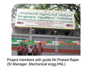
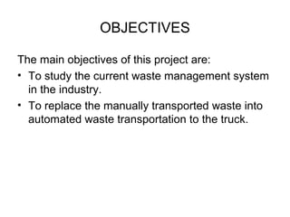
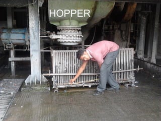
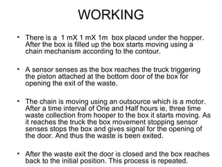
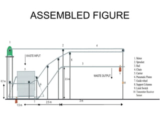
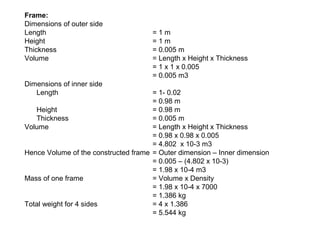
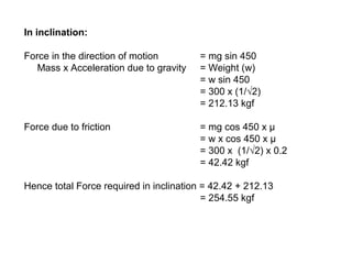
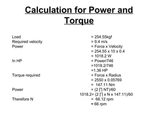
This document provides a design proposal for an Automated Wasted Disposal System (AWDS) for Hindustan Newsprint Limited. The system aims to automate the manual transport of waste from a hopper to a truck. Key elements include:
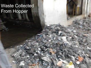
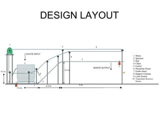
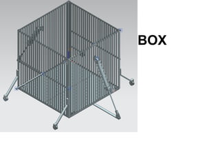
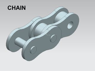
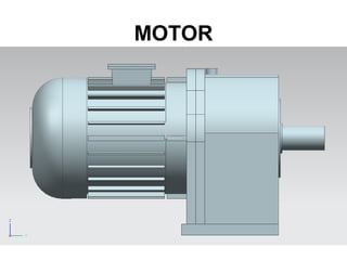
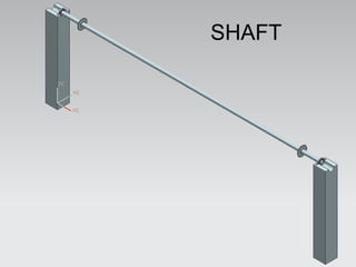
- A box that collects waste from the hopper and transports it along rails using a chain and sprocket drive powered by a motor.
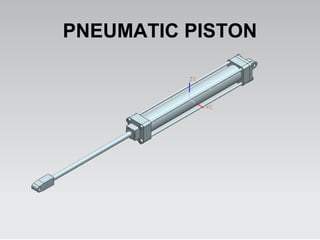
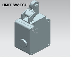
- Sensors to detect when the box is full and in position by the truck to trigger a pneumatic piston to open the bottom door and release the waste.
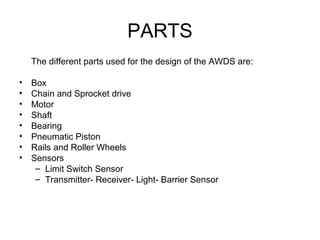
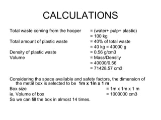
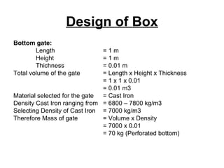
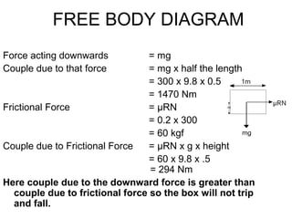
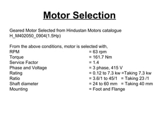
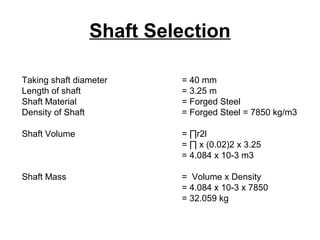
- Calculations to design the box, select appropriate chains, sprockets, motors and bearings to support the estimated 300kg load and 0.4m/


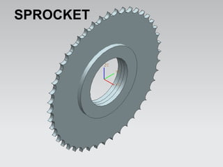

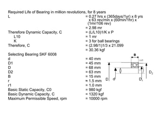
![Bearing Design
Density of Sprocket = Stainless Steel = 7480-8000 kg/m3
Selecting Density of Stainless Steel = 7500 kg/m3
Sprocket Volume = ∏r2l
= ∏ x ([118.6/2]2 – [40/2]2) x 2.8
= 27414.0778 mm3
Sprocket Mass = Volume x Density
= 27414.0778 x 10-9 x 7500
= 0.205 kg x 2
= 0.411 kg
Total Radial Load Acting on the Bearing = Shaft Mass + Bearing Mass
= 32.059 + 0.411
= 32.4702 kg
Axial Load, Fa = 0 kgf
Radial Load, Fr = 32.4702 /2
= 16.23 kg (for one bearing)
Equivalent Load , P = ( X Fr + Y Fa) S
Taking ,
Radial Factor, X = 1
Thrust Factor, Y = 0
Service Factor, S = 1.3
Therefore ,P = X Fr S
= 1 x 16.23 x 1.3
= 21.099 kg](https://image.slidesharecdn.com/15be3b1e-90fe-4436-b786-a59608d787e1-150812234516-lva1-app6891/85/PROJECT-DEMO-final-37-320.jpg)
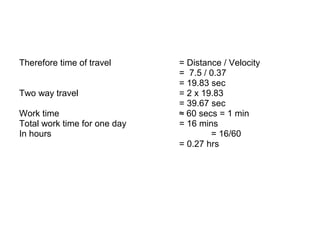
![Length of Chain at Inclination
According to Pythagoras Theorem
AC2 = √( AB2 +BC2)
AC = (2.52 + 2.52)
AC = 3.5 m
Total travel distance = 2.5 +3.5 + 1.5
= 7.5 m
Velocity, V = ω r
Radial Velocity, ω = [(2 x ∏ x N)/60]
rpm, N = 63 rpm
Therefore, V = [(2 x ∏ x N)/60] x r
= [(2 x ∏ x 63)/ 60] x (0.11469/2)
= 0.37 m/s](https://image.slidesharecdn.com/15be3b1e-90fe-4436-b786-a59608d787e1-150812234516-lva1-app6891/85/PROJECT-DEMO-final-38-320.jpg)
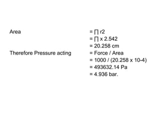
![Bearing Probability of Survival
We know that, C1 = (L101/L10)1/K x P1
= (L101/1)1/3 x 21.099
Therefore, L101 = 244870.336 mr
L/L101 = [ln(1/p1)/ln(1/p10)]1/b
L101 = calculated life of the selected bearing, for given load for 90%
survival
Ln(1/p10) = ln(1/0.9) = 0.1053
b = 1.34 for deep grove ball bearings
2.98/244870.336 = [ln (1/p)/ 0.1053)1/1.34
Therefore, p1 = 0.9999
= 99.99%](https://image.slidesharecdn.com/15be3b1e-90fe-4436-b786-a59608d787e1-150812234516-lva1-app6891/85/PROJECT-DEMO-final-41-320.jpg)


![[IJET-V1I5P7] Author: Galal Ali Hassaan](https://cdn.slidesharecdn.com/ss_thumbnails/ijet-v1i5p7-151120171139-lva1-app6891-thumbnail.jpg?width=640&height=640&fit=bounds)


