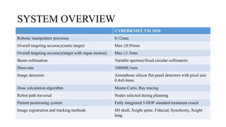
CYBERKNIFE®
DR.PRAVEEN KUMAR M
OVERVIEW
• CYBERKNIFE:
• INTRODUCTION
• SYSTEM OVERVIEW
• TREATMENT: Planning,Delivery
• TREATMENT DELIVERY SYSTEM HARDWARE
• TREATMENT DELIVERY SYSTEM SOFTWARE
• ADAPTIVE IMAGE ACQUISITION ALGORITHMS
INTRODUCTION
 John R. Adler-Neurosurgeon at Stanford University-1990
 Accuray Inc.,Sunnyvale,CA
 First patient treated in 1994
 FDA approved- 2001
BASIC PRINCIPLE
• 6MV LINAC mounted on a robotic manipulator delivering many
independently targeted (non-isocentric) and non-coplanar treatment
beams with high precision under continual X-ray image guidance
SYSTEM OVERVIEW
CYBERKNIFE VSI 2010
Robotic manipulator precision 0.12mm
Overall targeting accuracy(static target) Max ≤0.95mm
Overall targeting accuracy(target with organ motion) Max ≤1.5mm
Beam collimation Variable aperture/fixed circular collimators
Dose-rate 1000MU/min
Image detectors Amorphous silicon flat panel detectors with pixel size
0.4x0.4mm
Dose calculation algorithm Monte-Carlo, Ray tracing
Robot path traversal Nodes selected during planning
Patient positioning system Fully integrated 5-DOF standard treatment couch
Image registration and tracking methods 6D skull, Xsight spine, Fiducial, Synchrony, Xsight
lung
Treatment Planning
• 3D image acquisition- Target and OAR delineation
• Transferred to MultiPlan® TPS
• Beam-> Vector->Source point and direction point
• Source point-> Position of LINAC focal spot
• Direction point-> Within target volume
• Each source point is a node
• The complete set of nodes is a path set
• Different path sets -> range of non-coplanar beam directions
• Direction points based on beam generation mode-isocentric or non-
isocentric
• Isocentric mode -> Pseudo-isocentres within the patient model
resulting in one candidate beam from each node to each pseudo-
isocentre.
• Circular collimators-> isocentric mode-> spherical dose clouds
• Non-isocentric->multiple beams -> modulated fluence pattern->
independent field size and beam weight
• Optimal set of relative weighting factors for the candidate beam set
(i.e the dose delivered per beam) is obtained by inverse planning
• After optimization and approval-> plan transferred to the treatment
delivery system via the database server.
TREATMENT DELIVERY
• Beam alignment at time of treatment based on automatic registration
of DRRs generated from 3D patient model with live images acquired
using X-ray imaging system in the treatment room
• Live images and DRR combined and converted into a 3D
transformation by geometric backprojection.
• Image guidance system determines additional translational and
rotational corrections.
• Path traversal algorithm->Robot only moves between nodes
• Zero dose nodes- safety zone
• 30-60 sec image interval
• Large translations/rotation-> Treatment auto-pause
TREATMENT DELIVERY SYSTEM HARDWARE
• LINAC: X-band cavity magnetron, a standing wave, side-coupled
accelerating waveguide
• No bending magnet, no flattening filter
• Secondary collimation-> 12 fixed circular collimators with diameters
0.5-6cm.
• Iris™ Variable Aperture Collimator- same set of 12 field sizes with a
single variable aperture-> flexibility to apply any field size at any
beam position without the need to swap collimators during treatment
IRIS COLLIMATOR
• ROBOTIC MANIPULATOR: LINAC mounted on a KR240-2(Series
2000) robotic manipulator (Kuka Roboter GmbH,Augsburg,
Germany)
• Robot allows beam to be directed at unique points in space,i.e no
isocentre, also no coplanar constraints on beam geometry.
• Corrections relayed to the robotic manipulator->fine alignment is
achieved uniquely by adjusting the beam position and orientation
relative to the patient and not the patient relative to the beam
• X-Ray IMAGING SYSTEM:
• Two diagnostic X-ray sources in ceiling illuminate two X-ray
detectors by projecting square X-ray fields at 45° from vertical.
• Field size15 × 15 cm.(app)
• The flat panel X-ray detectors, consist of cesium-iodide scintillator
deposited directly on amorphous silicon photodiodes and generate
high-resolution digital images (1,024 × 1,024 pixels with 16-bit
resolution).
• STEREO CAMERA SYSTEM(Synchrony®)
TREATMENT DELIVERY SYSTEM SOFTWARE
• 6D SKULL:
• Image registration using high contrast bone information
• X-SIGHT SPINE:
• Based on high contrast bone information with image processing filters
• Tumors in spine, near the spine
• ROI: Vertebra of interest+2 adjacent vertebra
• XSIGHT LUNG:
• Global alignment-> spine alignment centre->tumor treatment centre.
• Direct tumor tracking is performed by matching image intensity
pattern of the tumor region in the DRRs to the corresponding region
in the treatment x-ray images.
• Image intensity pattern-> T>15mm diameter, located in peripheral,
apex lung regions
• FIDUCIAL TRACKING:
• For soft tissue targets not fixed relative to skull/spine eg. Prostate,
Pancreas, Liver, Lung ( Xsight unsuitable)
• Cylindrical gold seeds 0.8-1.2mm diameter, 3-6mm length
• 3-5 markers spaced atleast 1cm apart, 4-7 days for migration to settle
• Image registration based on alignment of these known DRR positions
with the marker locations extracted from treatment X-ray images.
ADAPTIVE IMAGE ACQUISITION ALGORITHM
• InTempo™ Adaptive Imaging System
• Synchrony Respiratory motion Tracking:
• Real time tracking for tumors that move with respiration
• No need for breath-holding, beam is dynamic throughout treatment
• Tumor position determined at multiple discrete time points by
acquiring orthogonal X-ray images
• A correlation model is generated by fitting the tumor positions at
different phases of breathing cycle to simultaneous external marker
position.
HASTA LA VISTA

Cyberknife®

  • 1.
  • 3.
    OVERVIEW • CYBERKNIFE: • INTRODUCTION •SYSTEM OVERVIEW • TREATMENT: Planning,Delivery • TREATMENT DELIVERY SYSTEM HARDWARE • TREATMENT DELIVERY SYSTEM SOFTWARE • ADAPTIVE IMAGE ACQUISITION ALGORITHMS
  • 4.
    INTRODUCTION  John R.Adler-Neurosurgeon at Stanford University-1990  Accuray Inc.,Sunnyvale,CA  First patient treated in 1994  FDA approved- 2001
  • 5.
    BASIC PRINCIPLE • 6MVLINAC mounted on a robotic manipulator delivering many independently targeted (non-isocentric) and non-coplanar treatment beams with high precision under continual X-ray image guidance
  • 7.
    SYSTEM OVERVIEW CYBERKNIFE VSI2010 Robotic manipulator precision 0.12mm Overall targeting accuracy(static target) Max ≤0.95mm Overall targeting accuracy(target with organ motion) Max ≤1.5mm Beam collimation Variable aperture/fixed circular collimators Dose-rate 1000MU/min Image detectors Amorphous silicon flat panel detectors with pixel size 0.4x0.4mm Dose calculation algorithm Monte-Carlo, Ray tracing Robot path traversal Nodes selected during planning Patient positioning system Fully integrated 5-DOF standard treatment couch Image registration and tracking methods 6D skull, Xsight spine, Fiducial, Synchrony, Xsight lung
  • 8.
    Treatment Planning • 3Dimage acquisition- Target and OAR delineation • Transferred to MultiPlan® TPS • Beam-> Vector->Source point and direction point • Source point-> Position of LINAC focal spot • Direction point-> Within target volume • Each source point is a node • The complete set of nodes is a path set
  • 10.
    • Different pathsets -> range of non-coplanar beam directions • Direction points based on beam generation mode-isocentric or non- isocentric • Isocentric mode -> Pseudo-isocentres within the patient model resulting in one candidate beam from each node to each pseudo- isocentre. • Circular collimators-> isocentric mode-> spherical dose clouds • Non-isocentric->multiple beams -> modulated fluence pattern-> independent field size and beam weight
  • 12.
    • Optimal setof relative weighting factors for the candidate beam set (i.e the dose delivered per beam) is obtained by inverse planning • After optimization and approval-> plan transferred to the treatment delivery system via the database server.
  • 13.
    TREATMENT DELIVERY • Beamalignment at time of treatment based on automatic registration of DRRs generated from 3D patient model with live images acquired using X-ray imaging system in the treatment room • Live images and DRR combined and converted into a 3D transformation by geometric backprojection. • Image guidance system determines additional translational and rotational corrections.
  • 14.
    • Path traversalalgorithm->Robot only moves between nodes • Zero dose nodes- safety zone • 30-60 sec image interval • Large translations/rotation-> Treatment auto-pause
  • 15.
    TREATMENT DELIVERY SYSTEMHARDWARE • LINAC: X-band cavity magnetron, a standing wave, side-coupled accelerating waveguide • No bending magnet, no flattening filter • Secondary collimation-> 12 fixed circular collimators with diameters 0.5-6cm. • Iris™ Variable Aperture Collimator- same set of 12 field sizes with a single variable aperture-> flexibility to apply any field size at any beam position without the need to swap collimators during treatment
  • 16.
  • 17.
    • ROBOTIC MANIPULATOR:LINAC mounted on a KR240-2(Series 2000) robotic manipulator (Kuka Roboter GmbH,Augsburg, Germany) • Robot allows beam to be directed at unique points in space,i.e no isocentre, also no coplanar constraints on beam geometry. • Corrections relayed to the robotic manipulator->fine alignment is achieved uniquely by adjusting the beam position and orientation relative to the patient and not the patient relative to the beam
  • 18.
    • X-Ray IMAGINGSYSTEM: • Two diagnostic X-ray sources in ceiling illuminate two X-ray detectors by projecting square X-ray fields at 45° from vertical. • Field size15 × 15 cm.(app) • The flat panel X-ray detectors, consist of cesium-iodide scintillator deposited directly on amorphous silicon photodiodes and generate high-resolution digital images (1,024 × 1,024 pixels with 16-bit resolution). • STEREO CAMERA SYSTEM(Synchrony®)
  • 19.
    TREATMENT DELIVERY SYSTEMSOFTWARE • 6D SKULL: • Image registration using high contrast bone information
  • 21.
    • X-SIGHT SPINE: •Based on high contrast bone information with image processing filters • Tumors in spine, near the spine • ROI: Vertebra of interest+2 adjacent vertebra
  • 22.
    • XSIGHT LUNG: •Global alignment-> spine alignment centre->tumor treatment centre. • Direct tumor tracking is performed by matching image intensity pattern of the tumor region in the DRRs to the corresponding region in the treatment x-ray images. • Image intensity pattern-> T>15mm diameter, located in peripheral, apex lung regions
  • 23.
    • FIDUCIAL TRACKING: •For soft tissue targets not fixed relative to skull/spine eg. Prostate, Pancreas, Liver, Lung ( Xsight unsuitable) • Cylindrical gold seeds 0.8-1.2mm diameter, 3-6mm length • 3-5 markers spaced atleast 1cm apart, 4-7 days for migration to settle • Image registration based on alignment of these known DRR positions with the marker locations extracted from treatment X-ray images.
  • 25.
    ADAPTIVE IMAGE ACQUISITIONALGORITHM • InTempo™ Adaptive Imaging System
  • 26.
    • Synchrony Respiratorymotion Tracking: • Real time tracking for tumors that move with respiration • No need for breath-holding, beam is dynamic throughout treatment • Tumor position determined at multiple discrete time points by acquiring orthogonal X-ray images • A correlation model is generated by fitting the tumor positions at different phases of breathing cycle to simultaneous external marker position.
  • 28.