Downloaded 392 times


![Fig3.22: IEEE 802 network standards
IEEE No. Name Title Reference
802.3 Ethernet CSMA/CD Networks (Ethernet) [IEEE 1985a]
802.4 Token Bus Networks [IEEE 1985b]
802.5 Token Ring Networks [IEEE 1985c]
802.6 Metropolitan Area Networks [IEEE 1994]
802.11 WiFi Wireless Local Area Networks [IEEE 1999]
802.15.1 Bluetooth Wireless Personal Area Networks [IEEE 2002]
802.15.4 ZigBee Wireless Sensor Networks [IEEE 2003]
802.16 WiMAX Wireless Metropolitan Area Networks [IEEE 2004a]
52](https://image.slidesharecdn.com/unit1-161221102632/85/CS6601-DISTRIBUTED-SYSTEMS-52-320.jpg)

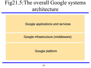
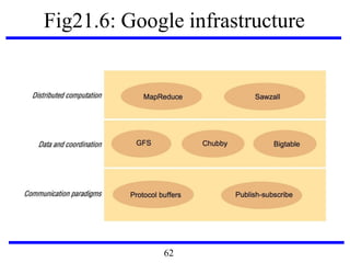


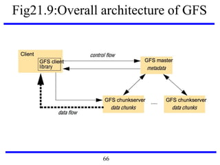


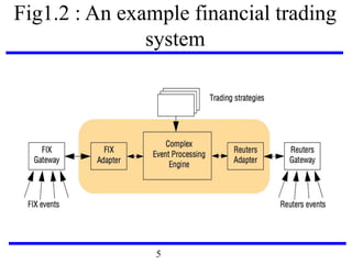
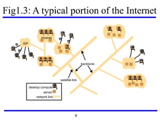
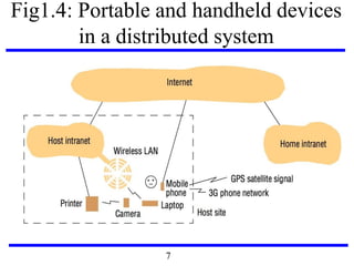
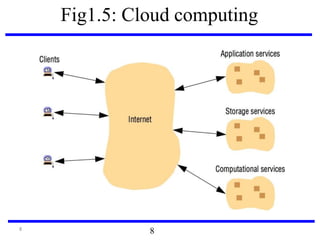
This document serves as an introduction to distributed systems, covering their concepts, design, and applications across various fields such as finance, healthcare, and education. It discusses key features like transparency, fault tolerance, and scalability, alongside trends exemplified by the Internet and the World Wide Web. The document further includes case studies, technical illustrations, and the architecture of distributed systems like Google's infrastructure.