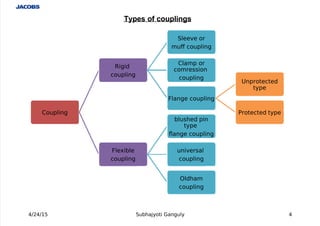
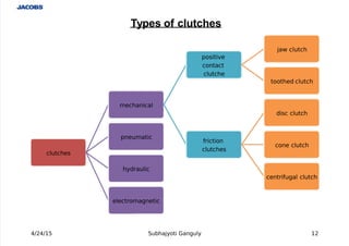
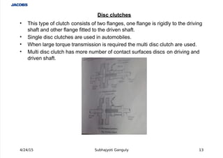
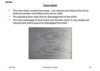
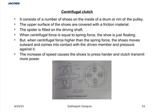
This document presents information on couplings, clutches, and brakes. It discusses different types of couplings like sleeve couplings, flange couplings, and universal couplings. It also describes clutches such as disc clutches, cone clutches, and centrifugal clutches. Finally, it covers brakes including block brakes, band brakes, and expanding shoe brakes. The document provides details on the components, operation, and applications of these power transmission elements.
PODSCAPE - Brochure 2023_ prefab homes in Bangalore India
Types of Couplings, Clutches and Brakes
1.
4/24/15 Subhajyoti Ganguly 1
P
r
e
s
e
n
t
a
t
i
o
no
nC
o
u
p
l
i
n
g
s
,
C
l
u
t
c
h
e
s&B
r
a
k
e
s
B
yS
u
b
h
a
j
y
o
t
i
G
a
n
g
u
l
y
2.
Coupling and Clutches are power transmission
elements. It is used for transmitting power from
one shaft to the another.
A Brake is a frictional device whose primary
function is to control the motion of the machine
member.
INTRODUCTION
4/24/15 Subhajyoti Ganguly 2
3.
Coupling
A coupling is a device used to connect or couple two shafts.
Shafts are mostly available up to 7 meters length due to
transport difficulty. To get a greater length , it is necessary to
joint two or more pieces of the shaft using coupling.
Shaft coupling are used in machinery for following purposes:
! To connect shafts of motor and generator which are
manufactured separately and to provide for disconnection
for repairs or alternations.
"! To reduce the transmission of shoc# loads from one shaft
to another.
$! To allow misalignment of the shaft or to introduce
mechanical fle%ibility.
&! To introduce protection against overloads.
4/24/15 Subhajyoti Ganguly 3
4.
Coupling
Rigid
coupling
Sleeve or
muf coupling
Clamp or
comreion
coupling
!lange coupling
"nprotected
type
#rotected type
!le$ible
coupling
bluhed pin
type
%ange coupling
univeral
coupling
&ldham
coupling
4/24/15 Subhajyoti Ganguly 4
Types of couplings
5.
'It is made from cast iron and very simple to design and manufacture.
'It consists of a hollow cylinder whose inner diameter is the same as
diameter of the shaft.
'The hollow cylinder is fitted over the end of the two shafts with the help of
taper sun# #ey.
'
A #ey and sleeve useful to transmit power from one shaft to the other shaft.
'The main disadvantage of this coupling is that it is difficult to assemble
when there is no perfect alignment between shafts.
4/24/15 Subhajyoti Ganguly 5
Sleeve or muff coupling
6.
' In this coupling , the muff or sleeve is made into two halves parts of cast
iron and they are join together by means of mild steel studs and nuts.
' The advantages of this coupling is that assembling of the coupling is
possible without change the position of shaft.
' This coupling is used for heavy power transmission at moderate speed.
4/24/15 Subhajyoti Ganguly '
Clamp or split muff or compression coupling
7.
' This coupling is having two separate cast iron flanges.
' (ach flange is mounted on the shaft end and #eyed to it.
' This coupling prevent catching clothes of wor#man.
' This flange couplings is most accurate and rigid.
' It is used for heavy power transmission at low speed.
4/24/15 Subhajyoti Ganguly (
Flange coupling
8.
' This is modified form of protected type flange coupling.
' This type of coupling has a pins and it wor# as a coupling bolts.
' The rubber or leather bushes are used over the pins.
' This coupling is used to connect of shafts which having the small parallel
misalignment, angular misalignment and a%ial displacement.
' This type of coupling is mostly used to couple an electric motor and
machine.
4/24/15 Subhajyoti Ganguly )
Bush pin type flange coupling
9.
' )niversal coupling consists of two similar for#s #eyed on the ends of the two
shafts.
' This coupling is used to connect two shafts whose a%is intersect.
' It also used to connect two shafts, where the angle between two shafts may
be varied when they rotate.
' It is widely used in automobile and machine tools.
4/24/15 Subhajyoti Ganguly *
Universal coupling
10.
' It consist of two flange and a central floating disc.
' This coupling is used in connecting two parallel shafts but not in alignment,
and their a%is are at small distance apart.
4/24/15 Subhajyoti Ganguly 1+
Olham!s coupling
11.
Clutches
*lutch is a one of the form of coupling.
*lutches is used to transmit the power from driving shaft
to driven shaft of machine which may be re+uired to start or
stop fre+uently.
It is so designed that the two members may be engaged
or disengaged whenever re+uired either by a hand operated
device or automatically by the action of some power driven
devices.
4/24/15 Subhajyoti Ganguly 11
13.
' This type of clutch consists of two flanges, one flange is rigidly to the driving
shaft and other flange fitted to the driven shaft.
' Single disc clutches are used in automobiles.
' hen large tor+ue transmission is re+uired the multi disc clutch are used.
' -ulti disc clutch has more number of contact surfaces discs on driving and
driven shaft.
4/24/15 Subhajyoti Ganguly 13
Disc clutches
14.
' The cone clutch consists two cones , one internal cone fi%ed to the driven
shaft and another cone fitted on the driven shaft.
' The operating lever used only for disengagement of the clutch.
' The main advantage of cone clutch over the disc clutch is very simple and
re+uired less a%ial pressure to disengaged the clutch.
4/24/15 Subhajyoti Ganguly 14
Cone clutch
15.
' It consists of a number of shoes on the inside of a drum or rim of the pulley.
' The upper surface of the shoes are covered with a friction material.
' The spider is fitted on the driving shaft.
' hen centrifugal force is e+ual to spring force, the shoe is just floating.
' ut, when centrifugal force higher than the spring force, the shoes moves
outward and comes into contact with the driven member and pressure
against it.
' The increase of speed causes the shoes to press harder and clutch transmit
more power.
4/24/15 Subhajyoti Ganguly 15
Centrifugal clutch
16.
' It is consists of segmental projections on one of the flange and
corresponding recesses on other flange on the driven shaft.
' /riving flange rigidly #eyed to the driving shaft while the other flange is
#eyed to driven shaft by splines so that it can slide on that shaft.
' The sliding flange engage with the fi%ed flange to transmit the motion and
power from driving shaft.
' This clutch is used for the transmission of power in agricultural e+uipment
li#e tractor, thresher, etc.
4/24/15 Subhajyoti Ganguly 1'
"a# clutch
17.
Brakes
A bra#e is a mechanical device which produces
frictional resistance against moving machine
member, in order to slow down the motion of
machine.
In the process of performing this function, the
bra#e absorbs #inetic energy of moving member
and the bra#e absorbs potential energy of
lowering member.
The energy absorbed by bra#es is released to
surrounding in form of heat.
4/24/15 Subhajyoti Ganguly 1(
19.
Single bloc# or shoe bra#e:
' A single bloc# is consists of a bloc# which is pressed against the rim of
revolving bra#e wheel drum.
' This bra#e is used in railway trains and tram cars.
' The prony bra#e is e%ample of bloc# bra#e.
4/24/15 Subhajyoti Ganguly 1*
Block $rake
20.
Dou$le $lock or shoe $rake%
' It consists of two bra#e bloc#s at the opposite ends of the wheel.
' These shoes apply force to both sides of wheel and reduces the
unbalanced force on the shaft.
' The spring pulls the upper end of bra#e arms together and bra#e is
applied.
' hen a force is applied to the bell cran# lever, the spring is compressed
and the bra#e is released.
' This bra#e is used on electric cranes.
' The bicycle bra#e is e%ample of double bloc# bra#e.
4/24/15 Subhajyoti Ganguly 2+
21.
' A band bra#e consists of a fle%ible steel band lined with friction material,
which wrap to the bra#e drum.
' hen an upward force is applied to the lever end, the lever turns about the
fulcrum pin and tightens the band on the drum and hence the bra#es are
applied.
' The friction between the band and the drum provides the bra#ing force.
' This type of bra#e is used in civil construction e+uipment and also in
automobiles as hand bra#e.
' The rope bra#e is e%ample of band bra#e.
4/24/15 Subhajyoti Ganguly 21
Ban $rake
22.
' An internal e%panding shoe bra#e consists of two shoes.
' The outer surface of the shoes are covered with friction material.
' (ach shoe is pivoted at one end about a fi%ed fulcrum and other end rests
against cam.
' hen the cam is operated, the shoe are pushed outwards against bra#e
drum.
' The friction between the shoes and the drum produces the bra#ing tor+ue.
' This type of bra#e is commonly used in motor cars and light truc#s.
4/24/15 Subhajyoti Ganguly 22
Internal e&paning shoe $rake