Downloaded 14 times

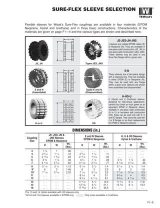


![DURA-FLEX COUPLING SELECTION
F2–2
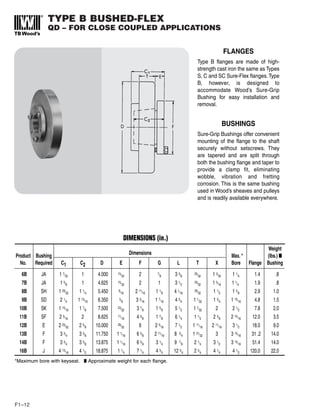
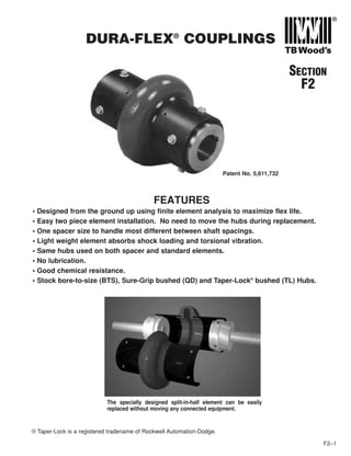
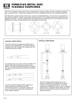
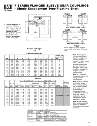
A. Determine the Prime Mover Classification
Prime Mover Class
• Electric Motors (Standard duty), Hydraulic Motors, Turbines A
• Gasoline or Steam Engines (4 or more cylinders) B
• Diesel or Gas Engines, High Torque Electric Motors C
B. Determine the Load Characteristics and the Service Factor
Prime Mover
Typical Applications Load Characteristics Class
A B C
Agitators (pure liquids), Blowers (centrifugal, Can and Bottle Uniform Even loads - no shock - non
Filling Machines, Conveyors - uniformly loaded or fed (belt, reversing - infrequent starts (up
chain, screw), Fans (centrifugal), Generators (uniform load), to 10 per hour) - low starting 1.0 1.5 2.0
Pumps (centrifugal), Screens (air washing, water), Stokers torques
(uniform load), Woodworking Machines (planers, routers, saws)
Beaters, Blowers (lobe, vane), Compressors (centrifugal, rotary), Moderate Uneven loads - moderate shock
Conveyors - non uniformly loaded or fed (belt, bucket, chain, shock Infrequent reversing-moderate
screw), Dredge Pumps, Fans (forced draft, propeller), Kilns, torques 1.5 2.0 2.5
Paper Mills (calendars, converting machines, conveyors, dryers,
mixers, winders), Printing Presses, Pumps (gear, rotary),
Shredders, Textile Machinery (dryers, dyers)
Cranes (bridge, hoist, trolley), Fans (cooling tower), Generators Heavy Uneven loads - heavy shock -
(welding), Hammer Mills, Mills (ball, pebble, rolling, tube, shock frequent starts and stops - high
tumbling), Pumps (oil well), Wire Drawing Machines starting torques - high inertia
peak loads 2.0 2.5 3.0
Note: The above applications depict the generally accepted conditions encountered in industry. Conditions subject to extreme
temperatures, abrasive dusts, corrosive liquids, excessively high starting torques, etc., must be considered as extra heavy
shock loads. These conditions will increase service factors. Consult TB Wood’s for these selections.
C. Calculate Design Horsepower or Design Torque
• If Prime Mover is a 1160, 1750, or 3500 rpm motor.
Design Hp = Prime Mover HP x Service Factor
Go to page F2—3 and reference the corresponding motor rpm column.
• If Prime Mover is not one of the three speeds listed above.
Design HP @ 100 rpm = (Primer Mover Hp x Service Factor x 100) / Coupling RPM
Go to page F2—3 and reference HP @ 100 RPM column.
• If Using Prime Mover Torque
Design Torque = Prime Mover Torque x Service Factor
Go to page F2—3 and reference Torque column.
D. Select Coupling (DURA-FLEX Couplings are sold by component)
A DURA-FLEX Assembly consists of one element (STD or Spacer) and two hubs (BTS or QD). Optional high speed rings may also
be ordered for spacer elements. Below is an ordering example for Dura-Flex Couplings.
Part # Description Size 20 Example
Element (1) WE2 - WE80 Standard element, sizes 2 through 80 WE20
WES2 - WES80 Spacer element, sizes 2 through 80 WES20
Hubs (2) WE[2-80] x Bore BTS hubs - stock bore (specify bore size) WE20H138
WE[4-80] - Bushing QD hubs (sizes 4 through 80, bushing not included) WE20H
WE[3-80] - TL Bushing TL hubs (sizes 3 through 80, bushing not included) WE20HTL
HS Rings (1) WE[20-80]R High speed rings - sizes 20-80 (standard for sizes 2-10) WE20R](https://image.slidesharecdn.com/coupling-180629054145/85/Coupling-21-320.jpg)
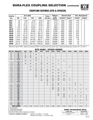


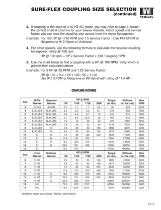
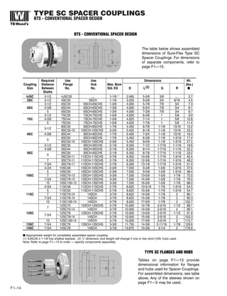
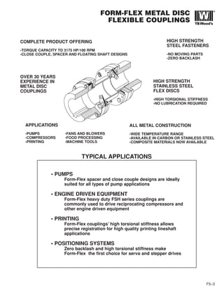
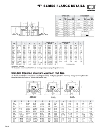
![DURA-FLEX METRIC COUPLING
SELECTION (continued)
F2–9
Part # Description Size 20 Example
Element (1) WE2M – WE80M Standard Metric Element, sizes 2 through 80 WE20M
WES2M – WES80M Spacer Metric Element, sizes 2 through 80 WES20M
Hubs (2) WE[2-80] MPB BTS Hubs – MPB suitable to rebore WE20MMPB
WE[3-80] – TL Bushing TL Hubs (sizes 3 through 80, bushing not included) WE20MTL
HS Rings (1) WE[20-80]R High speed rings – sizes 20-80 (standard for sizes 2-10) WE20RM
D. DURA-FLEX Couplings are sold by component
A DURA-FLEX Assembly consists of one element (STD or Spacer) and two hubs (BTS or QD). Optional high
speed rings may also be ordered for spacer elements. Below is an ordering example for Dura-Flex Couplings.
Coupling KW @ RPM Torque
Size 100 970 1450 3000 (Nm)
WE2M 0.22 2.17 3.24 6.71 21.47
WE3M 0.43 4.20 6.27 12.98 41.24
WE4M .66 6.37 9.52 19.69 62.14
WE5M 1.10 10.71 16.00 33.11 104.5
WE10M 1.72 16.64 24.87 51.45 163.8
WE20M 2.72 26.40 39.47 81.65 259.9
WE30M 4.32 41.88 62.61 129.53 412.4
WE40M 6.60 64.01 95.69 197.98 621.4
WE50M 9.05 87.81 131.27 271.58 864.3
WE60M 14.79 143.51 214.52 443.84 1412
WE70M 26.19 254.03 379.74 785.67 2500
WE80M 46.76 453.53 677.95 1402.66 4463
*Maximum spacer RPM = Maximum standard RPM if using optional high speed rings
Maximum Rpm Max. Misalignment
Standard Spacer* Angular
7500 7500 1.6 4˚
7500 7500 1.6 4˚
7500 7500 1.6 4˚
7500 7500 1.6 4˚
7500 7500 1.6 4˚
6600 4800 2.4 3˚
5800 4200 2.4 3˚
5000 3600 2.4 3˚
4200 3100 2.4 3˚
3800 2800 3.2 2˚
3600 2600 3.2 2˚
2000 1800 3.2 2˚
COUPLING RATINGS (STD & SPACER)
Parallel
(MM)
Stiffness
NM/RAD
358
532
607
1110
1790
3120
4770
7370
13900
18900
23200
34500](https://image.slidesharecdn.com/coupling-180629054145/85/Coupling-28-320.jpg)


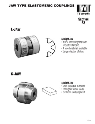


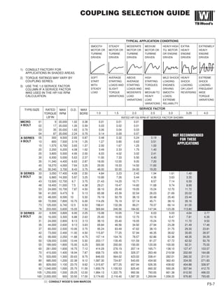


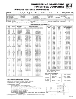


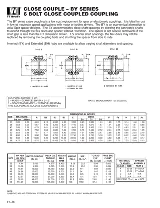

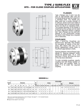
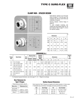
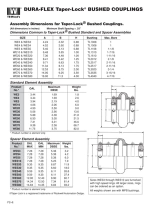
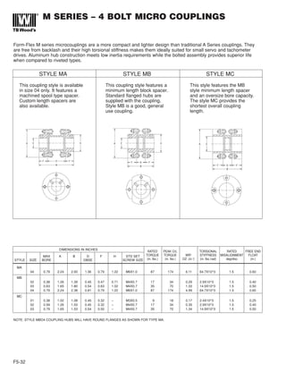
![SPACER – 4 BOLT
AK SERIES-STOCK LENGTH COUPLING
AP SERIES-CUSTOM LENGTH COUPLING
The AK and AP series couplings are standard design spacer couplings. They are made up of two hubs, a
one-piece machined spool spacer and two sets of flex discs with standard hardware, including stainless
steel flex discs. The AK is the stocked minimum length spacer. The AP is made-to-order to any custom
spacer length. AP series pricing is standard for any spacer length up to 9 inches.
RATED MISALIGNMENT: 1.0 DEG/DISC
COUPLING CONSISTS OF:
2 – HUBS – EXAMPLE- AJ25A x 1-3/4”
1 – SPACER ASSEMBLY – EXAMPLE- AK25SAA
THIS COUPLING IS SOLD AS COMPONENTS
MATERIAL SPACER ASSEMBLY
CLASSES PART #
CLASS SIZE AK AP
A 05-45 AKxxSAA APxxAddd
B 05-45 AKxxSAB APxxBddd
C 15-45 AKxxSAC APxxCddd
E MTO 15-45 AKxxSAE APxxEddd
SEE PAGE F5–4 xx = SIZE ddd=DBSE
HUB OPTIONS
HUB TYPE SIZE
AJ - STANDARD 05-45
AZ - OVERSIZE 05-45
QD BUSHING MT. 15-40
AC/AD CLAMP 05-25
AL LOCK ELEMENT 05-25
SEE PAGE F5–8
DIMENSIONS IN INCHES* FREE END
SIZE MAX BORE A Bmin Dmin F G H J FLOAT
AJ AZ (AK) (AK) +/- inch
05 0.87 1.13 2.65 3.72 1.72 1.00 0.24 1.30 0.54 0.030
10 1.25 1.63 3.19 4.06 2.06 1.00 0.27 1.80 0.56 0.040
15 1.37 1.88 3.65 4.67 2.41 1.13 0.32 2.00 0.88 0.042
20 1.62 2.13 4.08 5.02 2.38 1.32 0.34 2.40 0.79 0.055
25 2.00 2.38 4.95 6.16 2.92 1.62 0.45 2.80 1.00 0.060
30 2.38 2.88 5.63 7.57 3.81 1.88 0.47 3.30 1.14 0.065
35 2.88 3.75 6.63 8.81 4.31 2.25 0.55 4.15 0.97 0.085
40 3.25 4.00 7.64 9.88 4.88 2.50 0.60 4.65 1.30 0.100
* DIMENSIONS SHOWN ARE FOR AJ HUBS UNLESS OTHERWISE SPECIFIED.
F5–20
HP PER RATED TORQUE PEAK O/L AGMA 7 WEIGHT (lbs.) WR2
-(lb. in.2
) TORS. STIFFNESS
SIZE 100 RPM LB*IN TORQUE MAX AT MIN ADD PER AT MIN ADD PER 106
(lb. in./rad)
1.0 S.F (lb. in.) (lb. in.) RPM D in. OF D D in. OF D K factor Y factor
05 0.48 300 600 8,500 2.32 0.14 1.87 0.05 0.15 2.00
10 1.27 800 1,600 7,500 3.62 0.22 4.48 0.11 0.43 4.64
15 2.50 1,575 3,150 6,700 5.44 0.26 8.86 0.19 0.74 7.51
20 3.49 2,200 4,400 6,200 6.96 0.32 13.8 0.34 1.08 13.8
25 6.03 3,800 7,600 5,500 12.7 0.41 38.8 0.62 1.74 25.1
30 11.00 6,930 13,860 5,000 19.0 0.46 77.7 0.92 2.89 37.4
35 18.00 11,340 22,680 4,400 27.6 0.63 156 2.29 5.34 93
40 29.00 18,270 36,540 4,000 42.1 0.76 322 3.55 8.21 144
NOTES:
1) WEIGHT, WR2
AND TORSIONAL STIFFNESS VALUES SHOWN ARE FOR AJ HUBS AT MAXIMUM BORE SIZE.
2) TO CALCULATE TORSIONAL STIFFNESS FOR A GIVEN SPACER LENGTH, LET L= D - Dmin
TORSIONAL STIFFNESS = 1/[(1/K) + (L/Y)]
For type AP, specify the D (DBSE) dimension in 1/100th inches.
Example: AP10A350 specifies AP10 class A 3.50” DBSE.](https://image.slidesharecdn.com/coupling-180629054145/85/Coupling-61-320.jpg)
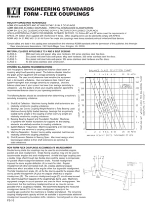
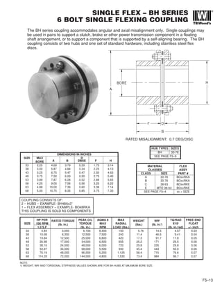
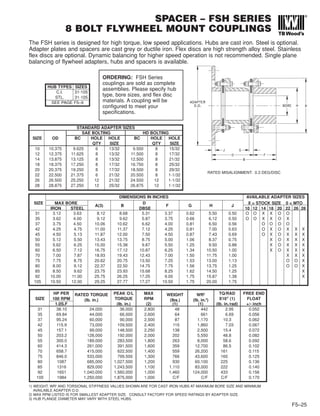
![SPACER – BP SERIES
6 BOLT SPACER COUPLING
F5–21
The BP series coupling is a standard design spacer coupling using the 6 bolt disc design. The coupling is
made up of two hubs, a one-piece machined spool spacer and two sets of flex discs with standard
hardware, including stainless steel flex discs. The BP is made-to-order to any custom spacer length.
BP series pricing is standard for any spacer length up to 9 inches.
RATED MISALIGNMENT: 0.7 DEG/DISC
HUB TYPES SIZES
BH 33-78
SEE PAGE F5–9
MATERIAL SPACER
CLASSES ASSEMBLY
CLASS SIZE PART #
A 33-73 BPxxAddd
B 33-78 BPxxBddd
C 38-63 BPxxCddd
E N/A N/A
SEE PAGE F5–4 ddd = DBSE
COUPLING CONSISTS OF:
2 – HUBS – EXAMPLE- BH33Ax2”
1 – SPACER ASSEMBLY – EXAMPLE-
BP33A500 (5”DBSE)
THIS COUPLING IS SOLD AS COMPONENTS
Specify the D (DBSE) dimension in 1/100th inches.
Example: BP33A350 specifies BP33 class A 3.50”
DBSE. Specify each hub bore size as required.
DIMENSIONS IN INCHES FREE
SIZE MAX END
BORE A Dmin F G H FLOAT
+/- inch
33 2.25 4.69 2.09 1.75 0.285 3.14 0.060
38 3.00 5.87 2.37 2.25 0.335 4.13 0.084
43 3.25 6.70 2.95 2.50 0.465 4.63 0.090
48 3.75 7.50 3.00 2.75 0.495 5.40 0.108
53 3.88 7.87 3.91 2.88 0.520 5.65 0.108
58 4.25 9.00 4.80 3.25 0.555 6.22 0.118
63 4.88 10.00 4.88 3.38 0.600 7.14 0.140
68 5.00 10.75 6.20 3.75 0.849 7.33 0.144
HP PER RATED TORQUE PEAK O/L AGMA 8 WEIGHT (lbs.) WR2
-(lb. in.2
) TORS. STIFFNESS
SIZE 100 RPM LB*IN TORQUE MAX AT MIN ADD PER AT MIN ADD PER x106
(lb. in./rad)
1.0 S.F (lb. in.) (lb. in.) RPM D in. OF D D in. OF D K factor Y factor
33 4.84 3,050 6,100 8,400 8.49 0.47 23.3 0.91 2.42 37.1
38 10.08 6,350 12,700 7,500 15.9 0.63 71.8 2.24 4.93 90.8
43 19.84 12,500 25,000 6,800 24.3 0.74 143 3.59 9.40 146.
48 26.98 17,000 34,000 6,500 33.2 0.87 248 5.79 13.2 235.
53 38.10 24,000 48,000 6,000 41.7 0.93 354 6.93 15.1 281.
58 53.97 34,000 68,000 5,500 65.1 0.98 707 8.14 23.7 330.
63 76.19 48,000 96,000 5,200 80.5 1.14 1,100 13.0 34.9 528.
68 114.29 72,000 144,000 4,800 104 1.17 1,560 14.7 44.0 597.
NOTES:
1) WEIGHT, WR2
AND TORSIONAL STIFFNESS VALUES SHOWN ARE FOR BH HUBS AT MAXIMUM BORE SIZE.
2) TO CALCULATE TORSIONAL STIFFNESS FOR A GIVEN SPACER LENGTH, LET L= D - Dmin
TORSIONAL STIFFNESS = 1/[(1/K) + (L/Y)]](https://image.slidesharecdn.com/coupling-180629054145/85/Coupling-62-320.jpg)
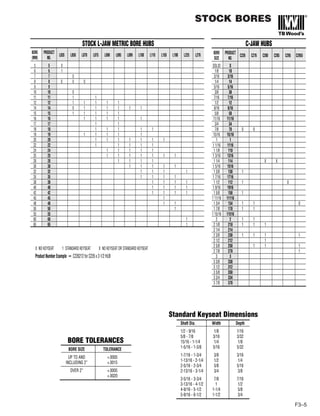
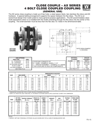
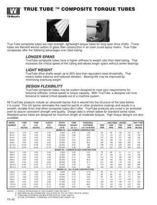
![SPACER – DP SERIES
8 BOLT SPACER COUPLINGS
F5-22
The DP series coupling is a fully machined spacer coupling using the 8 bolt disc design used for high
torque applications at higher speeds. The coupling is made up of two hubs, a one-piece machined spool
spacer and two sets of flex discs and hardware. The DP is made-to-order to any customer spacer length.
Both stainless and high strength alloy flex disc materials are available.
RATED MISALIGNMENT: 0.5 DEG/DISC
DIMENSIONS IN INCHES FREE END
SIZE MAX BORE A Dmin F1 F2 G H1 H2 FLOAT
DA DH DBSE DA DH DA DH +/- inch
DP31 3.38 3.63 7.81 4.38 2.84 3.37 0.44 5.22 5.50 0.052
DP35 3.75 4.00 8.69 4.75 3.28 3.75 0.54 5.71 5.88 0.056
DP37 4.00 4.50 9.69 5.00 3.56 4.00 0.69 6.18 6.50 0.062
DP42 4.50 4.75 10.50 5.13 3.97 4.25 0.69 6.70 7.00 0.067
DP45 4.75 5.13 11.31 5.25 4.50 4.50 0.75 7.20 7.44 0.072
DP50 5.00 5.38 12.88 7.25 4.72 5.00 0.96 7.93 8.38 0.082
DP55 5.50 6.00 14.44 7.62 5.31 5.50 1.04 8.95 9.44 0.092
DP60 6.00 6.50 16.00 8.13 6.00 6.00 1.10 9.89 10.25 0.102
DP70 7.00 7.50 18.25 9.25 7.00 7.00 1.40 11.06 11.75 0.115
SPECIFY BORES & DBSE
THIS COUPLING IS SOLD AS AN ASSEMBLY.
HP PER RATED TORQUE PEAK O/L AGMA 8 WEIGHT (lbs.) WR2
-(lb. in.2
) TORS. STIFFNESS
SIZE 100 RPM LB*IN TORQUE MAX AT MIN ADD PER AT MIN ADD PER x106
(lb. in./rad)
1.0 S.F (lb. in.) (lb. in.) RPM D in. OF D D in. OF D K factor Y factor
DP31 50.75 32,000 64,000 6,500 37.2 0.60 289 4.30 16.7 168
DP35 76.12 48,000 96,000 5,700 54.5 0.97 525 8.16 26.7 318
DP37 107.84 68,000 136,000 5,400 69.3 1.05 839 10.7 34.7 417
DP42 146.69 92,500 185,000 5,100 91.4 1.54 1,270 18.2 47.2 711
DP45 157.00 99,000 198,000 4,800 118 1.66 1,910 23.4 61.0 912
DP50 260.08 164,000 328,000 4,300 175 2.28 3,560 38.3 78.7 1,490
DP55 396.47 250,000 510,000 4,100 260 3.03 6,690 63.2 133 2,470
DP60 586.77 370,000 740,000 3,600 367 4.01 11,600 101 187 3,950
DP70 840.51 530,000 1,060,000 3,300 559 5.46 23,500 172 285 6,690
NOTES:
1) WEIGHT, WR2
AND TORSIONAL STIFFNESS VALUES SHOWN ARE FOR DA HUBS AT MAXIMUM BORE SIZE.
2) TO CALCULATE TORSIONAL STIFFNESS FOR A GIVEN SPACER LENGTH, LET L= D - Dmin
TORSIONAL STIFFNESS = 1/[(1/K) + (L/Y)]
MEETS API 610
9TH EDITION
WITH OPTIONAL
BALANCING](https://image.slidesharecdn.com/coupling-180629054145/85/Coupling-63-320.jpg)
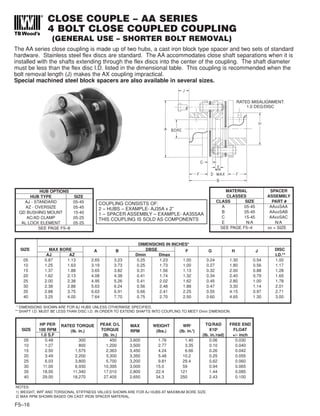
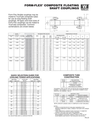
![SPACER – BF SERIES
6 BOLT DROP OUT SPACER COUPLING
F5-23
The BF series is designed for moderate service in higher speed applications. The coupling consists of
factory assembled spacer unit which mounts between two hubs. The spacer assembly drops out as one
unit for easy maintenance. The BF has all steel construction with standard stainless steel flex discs.
The coupling is manufactured to meet AGMA class 9 balance requirements. Dynamic balancing for higher
speed operation is also available. Standard length spacers are stocked. Pricing is standard for any spacer
length up to the Dmax value listed. Longer spacer lengths are also available.
RATED MISALIGNMENT: 0.5 DEG/DISC
SPECIFY BORES & DBSE
THIS COUPLING IS SOLD AS COMPONENTS
UNLESS BALANCED.
MEETS API 610
9TH EDITION
DIMENSIONS IN INCHES
SIZE MAX BORE DBSE Fs Fe Fl G Hs Hm
STD INTERM. LARGE A Dmin Dmax* STOCK STD EXT LRG MAX STD INTERM.
EXT HUB HUB INTERM. EXT
15(3) 1.50 1.88 2.38 3.65 3.43 9.00 3.5, 4.37 1.31 1.69 1.63 2.09 2.33 2.75
20(3) 1.88 2.13 2.75 4.19 3.43 9.00 3.5, 4.37, 5 1.56 2.06 1.81 2.56 2.81 3.00
33 2.25 - 3.25 4.93 3.09 9.00 3.5, 5, 7 2.00 2.50 2.06 3.13 3.38 -
38 3.00 - 4.00 6.00 3.50 9.00 5, 7 2.63 3.25 2.75 4.13 4.43 -
43 3.50 - 4.50 6.77 4.43 9.00 5, 7 3.12 3.75 3.00 5.00 5.25 -
48 3.75 - 5.00 7.62 4.50 9.00 5, 7 3.25 4.00 3.25 5.38 5.63 -
53 4.13 - - 8.00 5.69 9.00 7 3.63 4.38 - 5.75 6.13 -
58 4.63 - - 9.00 6.88 9.00 7 4.12 5.00 - 6.50 6.88 -
63 5.13 - - 10.00 6.93 9.00 7 4.50 5.38 - 7.25 7.63 -
68 5.63 - - 11.00 7.56 12.00 - 5.00 6.00 - 8.00 8.38 -
73 6.50 - - 12.75 11.00 15.00 - 5.13 6.38 - 8.38 9.38 -
78 7.50 - - 15.30 11.08 15.00 - 6.38 7.38 - 10.19 10.75 -
* Longer D dimensions are available. Consult factory for pricing.
NOTES:
1) WEIGHT, WR2
AND TORSIONAL STIFFNESS VALUES SHOWN ARE FOR STANDARD HUBS AT MAXIMUM BORE SIZE.
2) TO CALCULATE TORSIONAL STIFFNESS FOR A GIVEN SPACER LENGTH, LET L= D - Dmin
TORSIONAL STIFFNESS = 1/[(1/K) + (L/Y)]
3) CONSULT FACTORY FOR HIGHER SPEED OPERATION
4) SIZES 15-20 ARE A 4-BOLT DISC DESIGN, SIZES 33-68 ARE A 6-BOLT DISC DESIGN AND SIZES 73-78 ARE AN 8-BOLT DESIGN.
HP PER RATED TORQUE PEAK O/L AGMA 9 (3) WEIGHT (lbs.) WR2
-(lb. in.2
) TORSIONAL STIFFNESS FREE END
SIZE 100 RPM LB*IN TORQUE MAX. AT MIN. ADD PER AT MIN. ADD PER x106
(lb. in./rad) FLOAT
(4) 1.0 S.F (lb. in.) (lb. in.) RPM D (in.) OF D D (in.) OF D K factor Y factor +/- inch
15 2.50 1,575 3,150 13,500 7.22 0.12 11.9 0.05 0.52 2.09 0.045
20 3.49 2,200 4,400 12,500 9.31 0.19 19.9 0.15 0.92 3.72 0.055
33 6.27 3,950 7,900 11,000 13.1 0.47 39.3 0.91 3.32 37.0 0.060
38 13.10 8,255 16,510 9,800 24.3 0.63 114.0 2.23 6.91 90.7 0.076
43 21.43 13,500 27,000 8,800 44.5 0.70 276 3.05 9.66 124 0.090
48 29.21 18,400 36,800 8,300 54.3 0.79 422 4.61 12.8 187 0.108
53 38.10 24,000 48,000 7,800 72 0.88 633 5.92 14.9 240 0.108
58 65.08 41,000 82,000 7,000 107 0.98 1,200 8.14 23.4 330 0.118
63 76.19 48,000 96,000 6,700 134 1.14 1,870 13.0 33.5 528 0.140
68 114.29 72,000 144,000 6,200 188 1.48 3,020 16.2 44.7 569 0.144
73 198.41 125,000 250,000 5,700 272 2.02 5,890 27.0 75.1 1,100 0.156
78 369.84 233,000 466,000 5,000 475 3.21 14,700 63.8 142 2,590 0.170](https://image.slidesharecdn.com/coupling-180629054145/85/Coupling-64-320.jpg)

![FLOATING SHAFT – A5 SERIES
4 BOLT FLOATING SHAFT COUPLINGS
F5–26
The A5 series is used for spacer lengths that are longer than can be spanned economically with spacer
couplings. The A5 series has a welded tubular spacer assembly along with two hubs and standard
hardware, including stainless steel flex discs. The A5 is Made to Order to any custom spacer length.
A5 series standard pricing is listed for D dimensions up to 36” and for D dimensions from 36” to maximum
D at 1800 RPM.
RATED MISALIGNMENT: 1.0 DEG/DISC
ORDERING: A5 Series couplings are sold as complete assemblies. Please specify hub
types and bore sizes, DBSE (D) dimension, speed for dynamic balancing, and material class.
A coupling will be configured to meet your specifications.
ORDERING TYPE A6 FOR VERTICAL APPLICATIONS LONGER THAN 30” DBSE.
A THRUST BUTTON WILL BE ADDED ON THE LOWER END OF THE SPACER TO
SUPPORT THE WEIGHT OF THE SPACER
HUB OPTIONS
HUB TYPE SIZE
AJ - STANDARD 05-45
AZ - OVERSIZE 05-45
QD BUSHING MOUNT 15-40
AC/AD CLAMP 05-25
AL LOCK ELEMENT 05-25
SEE PAGE F5–8
MATERIAL
CLASSES
CLASS SIZE
A 05-45
B 05-45
C 15-45
E 15-45
SEE PAGE F5–4
DIMENSIONS IN INCHES* MAX DBSE (D INCHES)
SIZE MAX BORE A Dmin F G H FOR RPM SHOWN
AJ AZ 1800 1500 1200 900 750 600
05 0.87 1.13 2.65 4.00 1.00 0.24 1.30 51 56 62 71 78 87
10 1.25 1.63 3.19 4.00 1.00 0.27 1.80 62 69 76 88 96 107
15 1.37 1.88 3.65 5.00 1.13 0.32 2.00 64 71 79 91 99 111
20 1.62 2.13 4.08 5.00 1.32 0.34 2.40 73 81 90 103 113 126
25 2.00 2.38 4.95 5.00 1.62 0.45 2.80 79 87 97 112 122 137
30 2.38 2.88 5.63 6.00 1.88 0.47 3.30 85 94 102 120 132 147
35 2.88 3.75 6.63 7.00 2.25 0.55 4.15 97 107 119 137 150 168
40 3.25 4.00 7.64 7.00 2.50 0.60 4.65 103 113 126 146 160 178
* DIMENSIONS SHOWN ARE FOR AJ HUBS UNLESS OTHERWISE SPECIFIED
HP PER RATED TORQUE PEAK O/L WEIGHT (lbs.) WR2
-(lb. in.2
) TORS. STIFFNESS FREE END
SIZE 100 RPM (lb. in.) TORQUE AT ADD PER AT ADD PER 106
(lb. in./rad) FLOAT
1.0 S.F (lb. in.) D = 20” in. OF D D = 20” in. OF D K factor Y factor +/- inch
05 0.48 300 600 4.37 0.11 2.38 0.03 0.04 1.12 0.030
10 1.27 800 1,600 5.64 0.10 5.88 0.07 0.11 2.81 0.040
15 2.50 1,575 3,150 7.48 0.10 10.3 0.07 0.13 2.81 0.042
20 3.49 2,200 4,400 11.5 0.21 18.3 0.22 0.35 8.77 0.055
25 6.03 3,800 7,600 17.0 0.20 45.0 0.29 0.52 12.0 0.060
30 11.00 6,930 13,860 25.7 0.29 90.6 0.56 0.98 22.7 0.065
35 18.00 11,340 22,680 34.8 0.40 180 1.32 1.99 53.9 0.085
40 29.00 18,270 36,540 49.9 0.46 356 1.95 3.14 79.3 0.100
NOTES:
1) WEIGHT, WR2
AND TORSIONAL STIFFNESS VALUES SHOWN ARE FOR AJ HUBS AT MAXIMUM BORE SIZE.
2) TO CALCULATE TORSIONAL STIFFNESS FOR A GIVEN SPACER LENGTH, LET L= D - 20”
TORSIONAL STIFFNESS = 1/[(1/K) + (L/Y)]](https://image.slidesharecdn.com/coupling-180629054145/85/Coupling-67-320.jpg)
![FLOATING SHAFT – A7 SERIES
4 BOLT SEMI-FLOATING SHAFT COUPLINGS
F5–27
The A7 coupling is a single flexing coupling designed for use in widely spaced three bearing systems.
The shaft end of the coupling must be supported by a self-aligning bearing. A full floating coupling may be
used in combination with the semi-floating coupling to span longer distances, or a V-Belt drive or other
component may be mounted to the shaft end. This A7 is made-to-order to any custom spacer length.
A7 series standard pricing is listed at D dimensions up to 36 inches and D dimensions between 36 inches
and max L at 1800 RPM motor speed.
RATED MISALIGNMENT: 1.0 DEG/DISC
ORDERING: A7 Series couplings are sold as complete assemblies. Please specify hub
types and bore sizes, DBSE (D) dimension, speed for dynamic balancing, and material class.
A coupling will be configured to meet your specifications.
HUB OPTIONS
HUB TYPE SIZE
AJ - STANDARD 05-45
AZ - OVERSIZE 05-45
QD BUSHING MOUNT 15-40
AC/AD CLAMP 05-25
AL LOCK ELEMENT 05-25
SEE PAGE F5–8
MATERIAL
CLASSES
CLASS SIZE
A 10-45
B 05-45
C 15-45
E 15-45
SEE PAGE F5–4
DIMENSIONS IN INCHES* MAX DBSE (D INCHES)
SIZE MAX BORE A Dmin F G H K L M KEYWAY FOR RPM SHOWN
AJ AZ SIZE 1800 1500 1200 900 600
10 1.25 1.63 3.19 20 1.00 0.27 1.80 1.25 16.50 3.50 .25 x .12 62 69 76 88 107
15 1.37 1.88 3.65 20 1.13 0.32 2.00 1.25 16.06 3.94 .25 x .12 64 71 79 91 111
20 1.62 2.13 4.08 20 1.32 0.34 2.40 1.50 15.75 4.25 .37 x .18 73 81 90 103 126
25 2.00 2.38 4.95 20 1.62 0.45 2.80 1.75 15.25 4.75 .37 x .18 79 87 97 112 137
30 2.38 2.88 5.63 20 1.88 0.47 3.30 2.00 14.50 5.50 .50 x .25 85 94 102 120 147
35 2.88 3.75 6.63 20 2.25 0.55 4.15 2.50 13.25 6.75 .62 x .31 97 107 119 137 168
40 3.25 4.00 7.64 20 2.50 0.60 4.65 3.00 12.75 7.25 .75 x .37 103 113 126 146 178
* DIMENSIONS SHOWN ARE FOR AJ HUBS UNLESS OTHERWISE SPECIFIED
NOTES:
1) WEIGHT, WR2
AND TORSIONAL STIFFNESS VALUES SHOWN ARE FOR AJ HUBS AT MAXIMUM BORE SIZE.
2) TO CALCULATE TORSIONAL STIFFNESS FOR A GIVEN SPACER LENGTH, LET L= D - 20”
TORSIONAL STIFFNESS = 1/[(1/K) + (L/Y)]
HP PER RATED TORQUE PEAK O/L MAX WEIGHT (lbs.) WR2
-(lb. in.2
) TORS. STIFFNESS FREE END
SIZE 100 RPM (lb. in.) TORQUE RADIAL AT ADD/ (in.) AT MIN ADD/ (in.) 106
(lb. in./rad) FLOAT
1.0 S.F (lb. in.) LOAD-(lbs.) D = 20” OF D D = 20” OF D K factor Y factor +/- inch
10 1.27 800 1,600 34 5.37 0.10 3.30 0.07 0.26 2.81 0.020
15 2.50 1,575 3,150 56 6.65 0.10 5.72 0.07 0.28 2.81 0.021
20 3.49 2,200 4,400 125 11.0 0.21 11.0 0.22 0.56 8.77 0.027
25 6.03 3,800 7,600 183 14.7 0.20 24.9 0.29 0.91 12.0 0.030
30 11.00 6,930 13,860 275 19.7 0.29 52.4 0.56 1.52 22.7 0.032
35 18.00 11,340 22,680 400 34.7 0.40 106 1.32 3.03 53.9 0.042
40 29.00 18,270 36,540 600 51.6 0.46 211 1.95 5.26 79.3 0.050](https://image.slidesharecdn.com/coupling-180629054145/85/Coupling-68-320.jpg)
![FLOATING SHAFT – B5 SERIES
6 BOLT FLOATING SHAFT COUPLINGS
F5–28
The B5 series is used for spacer lengths that are longer than can be spanned economically with standard
spacer couplings. The B5 has a welded tubular spacer assembly along with two hubs and standard
hardware, including stainless steel flex discs. The B5 is made-to-order to any custom spacer length.
B5 series standard pricing is listed at D dimensions up to 36 inches and D dimensions between 36 inches
and max D at 1800 RPM motor speed.
Consult factory for vertical modifications and semi-floating designs.
RATED MISALIGNMENT: 0.7 DEG/DISC
ORDERING: B5 Series couplings are sold as complete assemblies. Please specify hub
types and bore sizes, DBSE (D) dimension, speed for dynamic balancing, and material class.
A coupling will be configured to meet your specifications.
MATERIAL
CLASSES
CLASS SIZE
A 33-78
B 33-78
C 38-63
E N/A
SEE PAGE F5–4
HUB TYPES SIZES
BH 33-78
SEE PAGE F5–9
DIMENSIONS IN INCHES* MAX DBSE (D INCHES)
SIZE MAX A Dmin F G H FOR RPM SHOWN
BORE 1800 1500 1200 900 750 600
33 2.25 4.69 4.25 1.75 0.285 3.14 79 87 97 112 122 137
38 3.00 5.87 6.00 2.25 0.335 4.13 97 107 119 137 150 168
43 3.25 6.70 7.00 2.50 0.465 4.63 103 113 126 146 160 178
48 3.75 7.50 7.50 2.75 0.495 5.40 113 125 139 160 175 196
53 3.88 7.87 7.50 2.88 0.520 5.65 113 125 139 160 175 196
58 4.25 9.00 7.50 3.25 0.555 6.22 123 136 151 170 186 208
63 4.88 10.00 7.50 3.38 0.600 7.14 123 136 151 170 186 208
68 5.00 10.75 8.00 3.75 0.849 7.33 130 142 159 183 201 225
HP PER RATED TORQUE PEAK O/L WEIGHT (lbs.) WR2
-(lb. in.2
) TORS. STIFFNESS FREE END
SIZE 100 RPM LB*IN TORQUE AT ADD PER AT ADD PER x106
(in. lbs./rad) FLOAT
1.0 S.F (in. lbs.) (in. lbs.) D = 20” in. OF D D = 20” in. OF D K factor Y factor +/- inch
33 4.84 3,050 6,100 14.4 0.20 32.7 0.29 0.48 12.0 0.060
38 10.08 6,350 12,700 29.1 0.39 113 1.28 1.77 51.9 0.084
43 19.84 12,500 25,000 41.0 0.44 210 1.88 2.89 76.4 0.090
48 26.98 17,000 34,000 60.0 0.52 402 3.10 4.57 126 0.108
53 38.10 24,000 48,000 67.4 0.52 494 3.10 5.52 126 0.108
58 53.97 34,000 68,000 85.5 0.63 874 5.43 8.44 220 0.118
63 76.19 48,000 96,000 108 0.63 1340 5.43 9.52 220 0.140
68 114.29 72,000 144,000 140 1.15 1940 13.37 19.9 543 0.144
NOTES:
1) WEIGHT, WR2
AND TORSIONAL STIFFNESS VALUES SHOWN ARE FOR BH HUBS AT MAXIMUM BORE SIZE.
2) TO CALCULATE TORSIONAL STIFFNESS FOR A GIVEN SPACER LENGTH, LET L= D - 20”
TORSIONAL STIFFNESS = 1/[(1/K) + (L/Y)]](https://image.slidesharecdn.com/coupling-180629054145/85/Coupling-69-320.jpg)
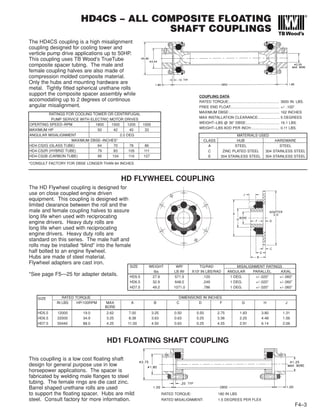
![FLOATING SHAFT – HFTH SERIES
8 BOLT FLOATING SHAFT COUPLINGS
F5–29
The HFTH series is designed for heavy duty applications that cannot use the A5 or B5 series. These
include high torque and engine driven applications. The HFTH uses a welded tubular spacer assembly.
Flex discs are high strength alloy steel. Stainless steel flex discs are optional. Dynamic balancing of the
spacer assembly is included. The HFTH is made-to-order to any custom spacer length. Large tube
designs are also available.
Consult factory for vertical modifications, and semi-floating designs or flywheel mounting.
ORDERING: HFTH Series couplings
are sold as complete assemblies.
Please specify hub speed for dynamic
balancing. A coupling will be
configured to meet your specification.
HUB TYPES SIZES
STL. 35-160
SEE PAGE F5–9
RATED MISALIGNMENT: 0.5 DEG/DISC
DIMENSIONS IN INCHES* MAX DBSE (D INCHES)
SIZE MAX BORE A Dmin F G H FOR RPM SHOWN
STEEL 1800 1500 1200 900 750 600
35 4.00 9.12 10.0 3.75 0.66 6.12 114 124 139 161 176 197
37 4.50 10.06 10.0 4.00 0.81 6.50 121 132 148 172 187 210
42 4.75 11.00 10.0 4.25 0.81 7.00 128 140 157 182 198 222
45 5.13 11.87 10.0 4.50 0.87 7.43 130 143 160 185 201 226
50 5.50 13.43 10.0 5.00 1.06 8.37 139 153 171 197 215 242
55 6.25 15.00 10.0 5.50 1.25 9.50 145 159 178 206 224 252
60 7.12 16.75 15.0 6.25 1.34 10.50 153 168 188 217 237 266
70 7.87 18.93 15.0 7.00 1.50 11.75 161 176 197 228 250 279
75 8.75 20.62 15.0 7.25 1.55 13.00 172 189 211 244 267 299
80 9.12 22.37 15.0 7.75 1.56 13.75 182 199 222 257 282 315
85 9.62 25.75 20.0 8.25 1.62 14.50
92 11.00 25.75 20.0 9.00 1.75 15.87
105 12.00 29.25 20.0 10.50 1.75 20.00
160 17.00 33.50 20.0 12.00 2.25 24.00
CONSULT TB WOOD’S
HP PER RATED TORQUE PEAK O/L WEIGHT (lbs.) (1) WR2
-(lb. in.2
) (1) TORS. STIFFNESS (1) FREE END
SIZE 100 RPM (lb. in.) TORQUE AT ADD PER AT ADD PER x106
(lb. in./rad) (2) FLOAT
1.0 S.F (lb. in.) D = 20” in. OF D D = 20” in. OF D K factor Y factor +/- inch
35 76.12 48,000 96,000 111 0.81 1,040 5 9 190 0.056
37 107.8 68,000 136,000 120 0.97 1,406 8.2 15 333 .062
42 146.7 92,500 185,000 186 1.14 2,520 13 21 537 0.067
45 157.0 99,000 198,000 201 1.14 3,370 13 23 537 0.072
50 260.1 164,000 328,000 311 1.31 6,430 20 38 810 0.082
55 396.5 250,000 500,000 374 1.95 10,100 37 67 1,510 0.092
60 586.8 370,000 740,000 556 3.21 18,600 75 110 3,020 0.102
70 840.5 530,000 1,060,000 769 3.21 33,000 75 134 3,020 0.115
75 1142 720,000 1,440,000 948 4.13 49,000 158 252 6,430 0.125
80 1507 950,000 1,900,000 1260 4.13 78,900 158 265 6,430 0.136
85 1903 1,200,000 2,400,000 0.140
92 2062 1,300,000 2,600,000 0.166
105 2855 1,800,000 3,600,000 0.170
160 3806 2,400,000 4,800,000 0.250
NOTES:
1) WEIGHT, WR2
AND TORSIONAL STIFFNESS VALUES SHOWN ARE FOR BH HUBS AT MAXIMUM BORE SIZE.
2) TO CALCULATE TORSIONAL STIFFNESS FOR A GIVEN SPACER LENGTH, LET L= D - 20”
TORSIONAL STIFFNESS = 1/[(1/K) + (L/Y)]
CONSULT TB WOOD’S](https://image.slidesharecdn.com/coupling-180629054145/85/Coupling-70-320.jpg)


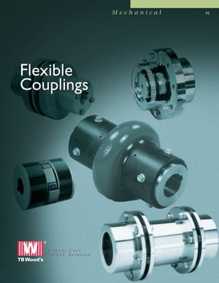
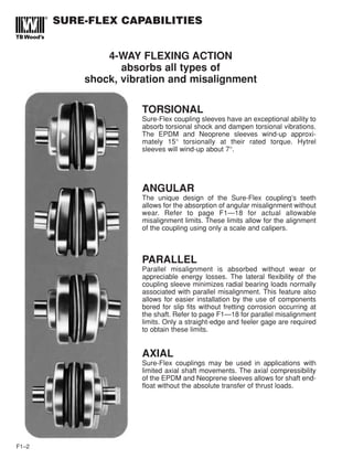
This document provides information on mechanical flexible couplings from TB Wood's, including elastomeric couplings called Sure-Flex couplings. It discusses the various components of Sure-Flex couplings including sleeves made from materials like EPDM, Neoprene, Hytrel, and Urethane. The document provides specifications for the sleeves, explains how to select couplings based on application and size, and outlines the features and benefits of Sure-Flex couplings like their ability to absorb shock and vibration through 4-way flexing action. Installation of Sure-Flex couplings is described as quick and easy with no need for lubrication or maintenance.


