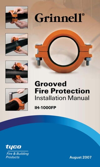
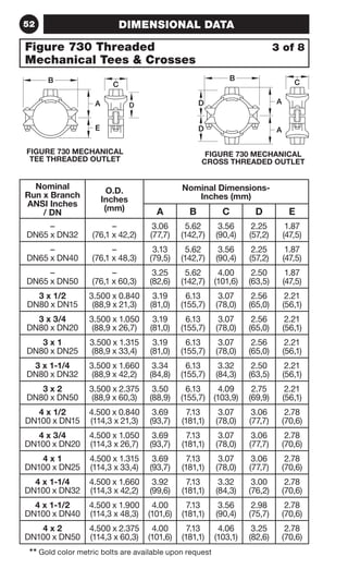
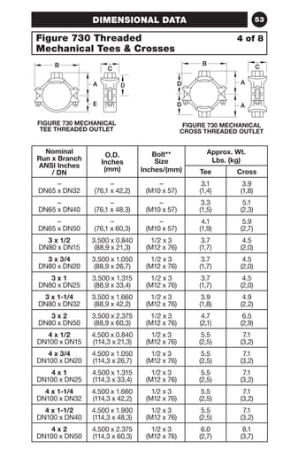
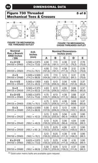
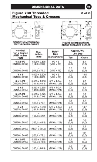
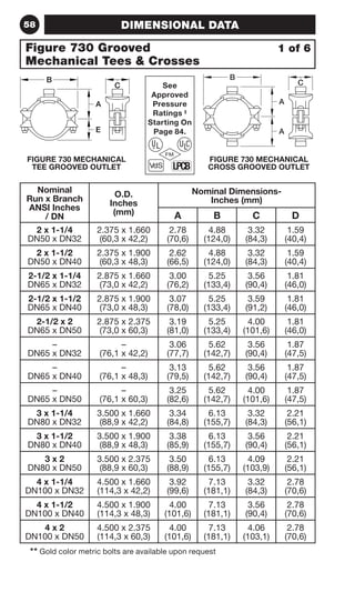
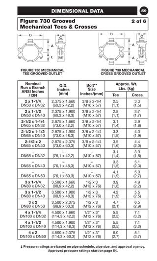
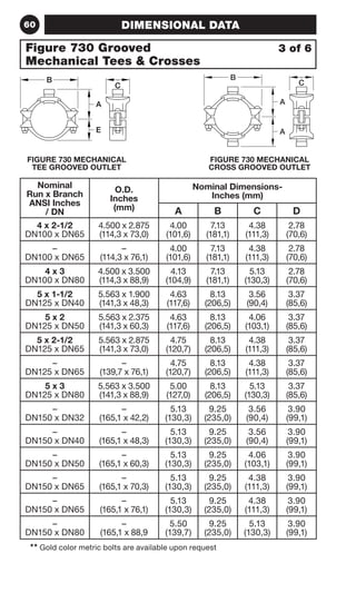
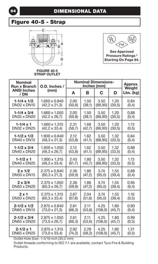
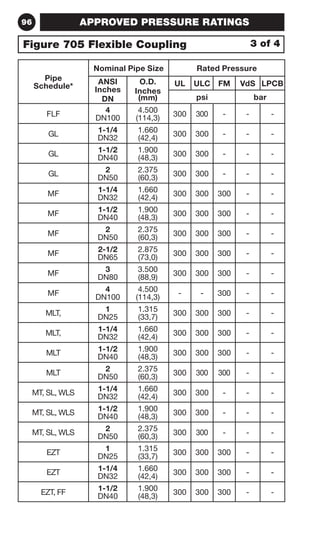
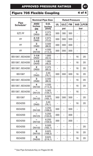
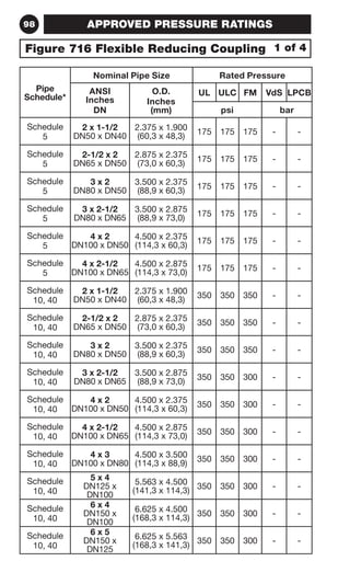
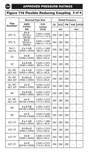
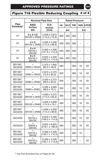
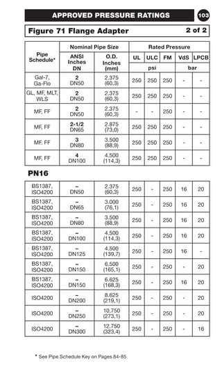
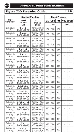
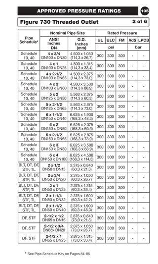
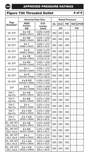
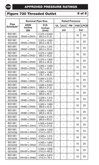
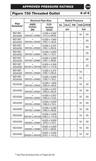
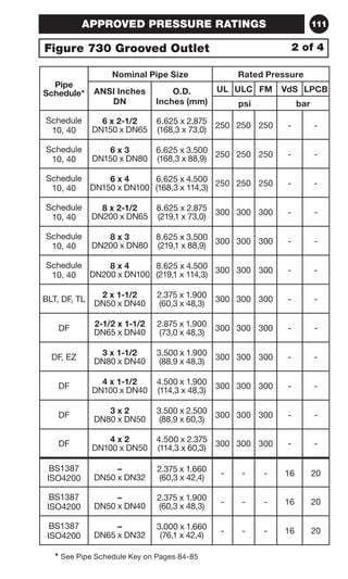
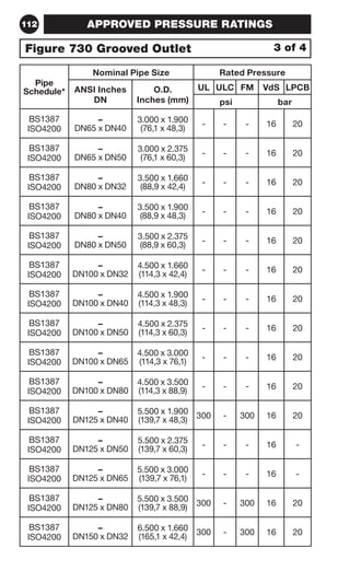
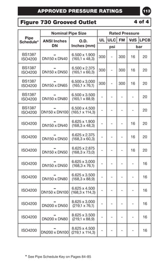
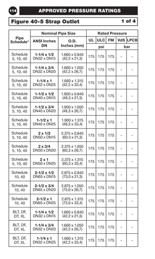
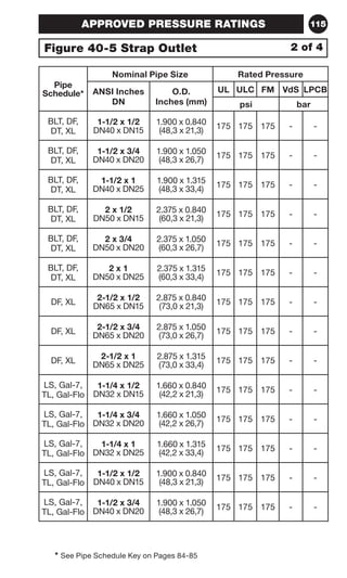
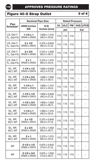
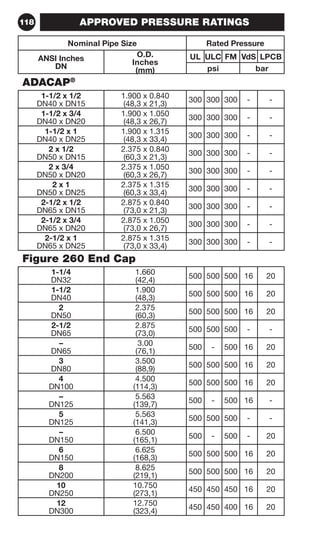
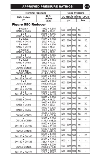
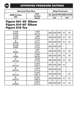
*URRYHG 
)LUH3URWHFWLRQ 
,QVWDOODWLRQ0DQXDO 
,+)3 
$XJXVW
Installation Handbook 
IH-1000FP 
Rev. 1 
AUGUST 2007 
Technical Services Tel: (800) 381-9312 / Fax: (800) 791-5500
2 TABLE OF CONTENTS 
GENERAL INFORMATION . . . . . . . . . . . . . . . . . . . . . . . . . . . . . 5 
ISO 9001:2000 Certified . . . . . . . . . . . . . . . . . . . . . . . . . . . . . . . 5 
General Code Groups . . . . . . . . . . . . . . . . . . . . . . . . . . . . . . . . 6 
Government Agencies . . . . . . . . . . . . . . . . . . . . . . . . . . . . . . . . 6 
UL 213 . . . . . . . . . . . . . . . . . . . . . . . . . . . . . . . . . . . . . . . . . . . . . 7 
Care and Maintenance . . . . . . . . . . . . . . . . . . . . . . . . . . . . . . . . 7 
Housing / Fitting Specifications . . . . . . . . . . . . . . . . . . . . . . . . . 7 
Coupling Nut / Bolt Specifications . . . . . . . . . . . . . . . . . . . . . . . 8 
Grinnell Grooved Fittings - Pressure Loss . . . . . . . . . . . . . . . . 11 
Gasket Specifications . . . . . . . . . . . . . . . . . . . . . . . . . . . . . . . . 12 
Pipe Support . . . . . . . . . . . . . . . . . . . . . . . . . . . . . . . . . . . . . . . 13 
Paint Specifications . . . . . . . . . . . . . . . . . . . . . . . . . . . . . . . . . 13 
Groove Specifications . . . . . . . . . . . . . . . . . . . . . . . . . . . . . . . 14 
INSTALLATION INSTRUCTIONS . . . . . . . . . . . . . . . . . . . . . . . 22 
Figure 772  577 Rigid Coupling . . . . . . . . . . . . . . . . . . . . . . . 22 
Figure 705 Flexible Coupling . . . . . . . . . . . . . . . . . . . . . . . . . . 24 
Figure 716 Flexible Reducing Coupling . . . . . . . . . . . . . . . . . . 26 
Figure 71 Flange Adapter . . . . . . . . . . . . . . . . . . . . . . . . . . . . . 28 
Figure 730 Mechanical Outlet . . . . . . . . . . . . . . . . . . . . . . . . . 30 
Figure 40-5 Strap Outlet . . . . . . . . . . . . . . . . . . . . . . . . . . . . . . 34 
DIMENSIONAL DATA . . . . . . . . . . . . . . . . . . . . . . . . . . . . . . . . 36 
Figure 772 Rigid Coupling - Patented . . . . . . . . . . . . . . . . . . . 36 
Figure 577 Rigid Coupling . . . . . . . . . . . . . . . . . . . . . . . . . . . . 38 
Figure 705 Flexible Coupling . . . . . . . . . . . . . . . . . . . . . . . . . . 40 
Figure 716 Flexible Reducing Coupling . . . . . . . . . . . . . . . . . . 44 
Figure 71 Flange Adapter . . . . . . . . . . . . . . . . . . . . . . . . . . . . . 46 
Figure 730 Threaded Mechanical Tees  Crosses . . . . . . . . . 50 
Figure 730 Grooved Mechanical Tees  Crosses . . . . . . . . . . 58 
Figure 40-5 - Strap . . . . . . . . . . . . . . . . . . . . . . . . . . . . . . . . . . 64 
Figure 260 - End Cap . . . . . . . . . . . . . . . . . . . . . . . . . . . . . . . . 65 
Figure 510  310 - 90° Elbow . . . . . . . . . . . . . . . . . . . . . . . . . . 66 
Figure 501  301 - 45° Elbow . . . . . . . . . . . . . . . . . . . . . . . . . . 67 
Figure 510S 90° Elbow  519S Tee - Short Pattern . . . . . . . . . 68 
Figure 510DE 90° Elbow . . . . . . . . . . . . . . . . . . . . . . . . . . . . . . 69 
Figure 519 - Tee . . . . . . . . . . . . . . . . . . . . . . . . . . . . . . . . . . . . 70 
Figures 312 - 22-1/2°  313 - 11-1/4° Elbow . . . . . . . . . . . . . . . 71 
Figure 321 Reducing Tee . . . . . . . . . . . . . . . . . . . . . . . . . . . . . 72 
Figure 327 Cross . . . . . . . . . . . . . . . . . . . . . . . . . . . . . . . . . . . 74 
Figure 341 Flange Adapter . . . . . . . . . . . . . . . . . . . . . . . . . . . . 75 
Figure 550  350 Concentric Reducers . . . . . . . . . . . . . . . . . . 76 
Figure 391, 392  393 Adapter Nipples . . . . . . . . . . . . . . . . . . 78 
ADACAP® . . . . . . . . . . . . . . . . . . . . . . . . . . . . . . . . . . . . . . . . . 79 
Model BFV-N Grooved End Butterfly Valve . . . . . . . . . . . . . . . 80 
Model CV-1F Check Valve . . . . . . . . . . . . . . . . . . . . . . . . . . . . 82
TABLE OF CONTENTS 3 
APPROVED PRESSURE RATINGS . . . . . . . . . . . . . . . . . . . . . 84 
Pipe Schedule Key . . . . . . . . . . . . . . . . . . . . . . . . . . . . . . . . . . 84 
Figure 772 Rigid Coupling . . . . . . . . . . . . . . . . . . . . . . . . . . . . 86 
Figure 577 Rigid Coupling . . . . . . . . . . . . . . . . . . . . . . . . . . . . 90 
Figure 705 Flexible Coupling . . . . . . . . . . . . . . . . . . . . . . . . . . 94 
Figure 716 Flexible Reducing Coupling . . . . . . . . . . . . . . . . . . 98 
Figure 71 Flange Adapter . . . . . . . . . . . . . . . . . . . . . . . . . . . . 102 
Figure 730 Threaded Outlet . . . . . . . . . . . . . . . . . . . . . . . . . . 104 
Figure 730 Grooved Outlet . . . . . . . . . . . . . . . . . . . . . . . . . . . 110 
Figure 40-5 Strap Outlet . . . . . . . . . . . . . . . . . . . . . . . . . . . . . 114 
ADACAP® . . . . . . . . . . . . . . . . . . . . . . . . . . . . . . . . . . . . . . . . 118 
Figure 260 End Cap . . . . . . . . . . . . . . . . . . . . . . . . . . . . . . . . 118 
Figure 550 Reducer . . . . . . . . . . . . . . . . . . . . . . . . . . . . . . . . 119 
Figure 501 45° Elbow . . . . . . . . . . . . . . . . . . . . . . . . . . . . . . . 120 
Figure 510 90° Elbow . . . . . . . . . . . . . . . . . . . . . . . . . . . . . . . 120 
Figure 519 Tee . . . . . . . . . . . . . . . . . . . . . . . . . . . . . . . . . . . . . 120 
Figure 510S 90° Elbow . . . . . . . . . . . . . . . . . . . . . . . . . . . . . . 121 
Figure 519S Tee . . . . . . . . . . . . . . . . . . . . . . . . . . . . . . . . . . . 121 
Figure 510DE Drain Elbow . . . . . . . . . . . . . . . . . . . . . . . . . . . 121 
Figure 391 GRV x Male Thread Adapter Nipples . . . . . . . . . . 122 
Figure 392 GRV x GRV Adapter Nipples . . . . . . . . . . . . . . . . 122 
Figure 393 GRV x Bevel Adapter Nipples . . . . . . . . . . . . . . . 122 
Figure 341 GRV x Flange Adapter 150 Lbs. . . . . . . . . . . . . . . 122 
Figure 327 Cross . . . . . . . . . . . . . . . . . . . . . . . . . . . . . . . . . . 122 
Figure 312 22-1/2° Elbow . . . . . . . . . . . . . . . . . . . . . . . . . . . . 123 
Figure 313 11-1/4° Elbow . . . . . . . . . . . . . . . . . . . . . . . . . . . . 123 
Figure 321 Reducing Tee . . . . . . . . . . . . . . . . . . . . . . . . . . . . 123 
Figure 350 Fabricated GRV x GRV Reducer . . . . . . . . . . . . . 123 
SYSTEM DESIGN . . . . . . . . . . . . . . . . . . . . . . . . . . . . . . . . . . 124 
Rigid Couplings . . . . . . . . . . . . . . . . . . . . . . . . . . . . . . . . . . . 124 
Flexible Couplings . . . . . . . . . . . . . . . . . . . . . . . . . . . . . . . . . 124 
Rotational Movement . . . . . . . . . . . . . . . . . . . . . . . . . . . . . . . 125 
Linear Movement . . . . . . . . . . . . . . . . . . . . . . . . . . . . . . . . . . 125 
Linear Movement (Flexible Couplings) . . . . . . . . . . . . . . . . . . 126 
Angular Movement . . . . . . . . . . . . . . . . . . . . . . . . . . . . . . . . . 127 
Angular Deflection . . . . . . . . . . . . . . . . . . . . . . . . . . . . . . . . . 127 
Expansion / Contraction . . . . . . . . . . . . . . . . . . . . . . . . . . . . . 128 
Thermal Movement . . . . . . . . . . . . . . . . . . . . . . . . . . . . . . . . . 128 
Misalignment and Deflection . . . . . . . . . . . . . . . . . . . . . . . . . 132 
ENGINEERING REFERENCE . . . . . . . . . . . . . . . . . . . . . . . . . 134 
Decimal Equivalents of Fractions . . . . . . . . . . . . . . . . . . . . . . 134 
Standard Conversion Factors . . . . . . . . . . . . . . . . . . . . . . . . 135 
Minutes Converted To Decimals Of A Degree . . . . . . . . . . . . 136 
Water Feet Head Conversion . . . . . . . . . . . . . . . . . . . . . . . . . 137 
Pipe Thickness And Weight Per Line Foot . . . . . . . . . . . . . . . 138 
COMPANY INFORMATION . . . . . . . . . . . . . . . . . . . . . . . . . . . 140 
Limited Warranty . . . . . . . . . . . . . . . . . . . . . . . . . . . . . . . . . . 140 
Availability and Service . . . . . . . . . . . . . . . . . . . . . . . . . . . . . 140 
Ordering Information . . . . . . . . . . . . . . . . . . . . . . . . . . . . . . . 140 
Disclaimer . . . . . . . . . . . . . . . . . . . . . . . . . . . . . . . . . . . . . . . . 141
4 TYCO FIRE  BUILDING PRODUCTS 
Tyco Fire  Building Products is ISO 9001 Certified with products 
manufactured in our state of the art ductile iron foundry and manufacturing 
facilities. We are committed to maintaining our role in the fire protection 
industry through aggressive research and development. The products 
that will improve our industry are being designed today. With this level of 
investment and commitment, Tyco Fire  Building Products is prepared 
to become the industry standard. 
Tyco Fire  Building Products is a world leader in the manufacture and 
distribution of fire protection products. Years of development, engineering, 
pattern and tooling manufacturing, and the acquisition of the necessary 
resources has provided the finest products available on the market today. 
Tyco Fire  Building Products manufactured domestically or world-wide 
are offered to scrutinizing quality standards as set forth by independent 
testing laboratories. 
Our Global Technology Center located in Cranston, RI, directs product 
development from concept through design, testing and manufacturing, 
then forwards all aspects of application engineering and quality assurance. 
Owners, architects, consulting engineers, contractors, and tenants 
demand the most dependable quality mechanical products for their piping 
systems - the Global Technology Center ensures their demands are met 
each and every time. 
Throughout this handbook, nominal pipe sizes are referred to in “ANSI 
Inches” and “DN”. “ANSI Inches” is a nominal pipe size designation 
derived from the older IPS (inside pipe diameter) in inches. Sizes offered 
in ANSI Inches directly correlate to nominal pipe sizes recognized in ANSI 
(American National Standard Institute) pipe standards. “DN” refers to 
nominal pipe sizes in “diameter nominal” and is a dimensionless designator 
for nominal pipe sizes in metric. Certain DN sizes (e.g., DN65, DN125, and 
DN150) are offered in multiple actual outside diameters. Consequently, 
when specifying by DN pipe size, the O.D. (outside diameter) must be 
specified as well. 
WARNING 
It is the Designer’s responsibility to select products suitable for the intended 
service and to ensure that pressure ratings and performance data are not 
exceeded. Always read and understand the installation instructions. Never 
remove any piping component nor correct or modify any piping deficiencies 
without first depressurizing and draining the system. Material and gasket 
selection should be verified to be compatible for the specific application. 
The products described herein must be installed and maintained in compliance 
with this document, as well as with the applicable standards of the National 
Fire Protection Association, in addition to the standards of any other 
authorities having jurisdiction. Failure to do so may impair the performance 
of this device. 
The owner is responsible for maintaining their fire protection system and 
devices in proper operating condition. The installing contractor or sprinkler 
manufacturer should be contacted with any questions. 
1. Read and understand all instructions before installing any 
Tyco Fire  Building Products. 
2. Be sure to wear appropriate safety equipment. 
3. Verify that the system is de-pressurized and drained before starting any 
installation, repair, or modification.
GENERAL INFORMATION 5 
ISO 9001:2000 Certified 
Tyco Fire  Building Products Products are manufactured according 
to ISO 9001:2000 quality assurance standards. 
further clarification regarding the scope of this certificate and the applicability of ISO 9001:2000 requirements may be obtained by consulting the organization
6 GENERAL INFORMATION 
General Code Groups, Associations, 
Laboratories And Approval Bodies 
American Bureau of Shipping (ABS) 
American National Standards Institute / American 
Water Works Association (ANSI / AWWA) 
American Petroleum Institute (API) - API Std. 5L, Sect. 7.5 
American Society of Heating, Refrigerating and 
Air Conditioning Engineers (ASHRAE) 
American Society of Mechanical Engineers (ASME) 
Power Piping, B-31.1; Chemical Plant and Petroleum 
Refinery Piping, B-31.3; Refrigeration Piping, B-31.5; 
Building Services Piping, B-31.9. 
Building Officials and Code Administrators (BOCA) 
Bureau Veritas (BV) 
Factory Mutual Engineering Corp. (FM) - 
Approved for Fire Protection Services 
International Association of Plumbing and Mechanical Officers (IAPMO) 
Loss Prevention Certification Board (LPCB) - 
Approved for Fire Protection Services 
Material Equipment and Acceptance (MEA) 
National Fire Protection Association (NFPA) 
National Sanitation Foundation (NSF) 
New York Board of Standards and Appeals (NY-BSA) 
Southern Building Code Congress International 
(SBCCI) - Standard Plumbing 
Underwriter’s Laboratories, Inc. (UL) - 
Listed for Fire Protection Services 
Underwriters Laboratories of Canada (ULC) - 
Listed for Fire Protection Services 
Uniform Plumbing Code (UPC) 
Verband der Sachversicherer e.V. (VdS) - 
Approved for Fire Protection Services 
Government Agencies 
Coast Guard - Approved each vessel individually 
Corps of Engineers (COE) - GEGS 15000 
Federal Aviation Administration (FAA) - 
HVAC, Plumbing and Fire Protection 
Federal Housing Administration (FHA) 
General Services Administration (GSA) - 15000 Series 
Military Specifications (MIL) - MILP - 10388 Fittings; 
MIL - C - 10387 Couplings; 
MIL - P - 11087A (CE) Steel Pipe, 
Grooved MIL - I - 45208 Inspection Procedure 
National Aeronautics and Space Administration (NASA) 
Naval Facilities Engineering Command (NAVFAC)- 
NFGS 15000 Series 
National Institute of Health (NIH) - Dept. of Health - 15000 Series 
Veterans Affairs (VA) - 15000 Series
GENERAL INFORMATION 7 
NOTE 
UL 213 
Bolt torque information for couplings is provided as required by 
UL 213, Section 17. 
UL 213 
Standard For Rubber Gasketed Fittings For 
Fire-Protection Service 
Third Edition – July 12, 2001 
INSTRUCTIONS 
17 Installation Instructions 
17.1 Installation instructions shall be provided with each shipment 
of fittings, and shall include at least the following items: 
a) Assembly procedure for installation of fittings. 
b) Pipe end specifications, when required, with which fitting is 
intended to be used. 
c) Required torque for bolts (if bolts are used), when not marked 
on the fitting. 
d) Maximum allowable deflection for flexible fittings. 
Care and Maintenance 
The owner is responsible for the inspection, testing, and maintenance of 
their fire protection system and devices in accordance with the applicable 
standards of the National Fire Protection Association (e.g., NFPA 25), in 
addition to the standards of any authority having jurisdiction. The installing 
contractor or product manufacturer should be contacted relative to any 
questions. Any impairment must be immediately corrected. It is recommended 
that automatic sprinkler systems be inspected, tested, and maintained by 
a qualified Inspection Service. 
Housing / Fitting Specifications 
The applicable material specifications for ductile iron, galvanizing and 
rubber apply: 
ASTM A-536 - (Cast Products) 
Standard Specification for Ductile Iron Castings 
Grade 65-45-12, Tensile Strength, minimum psi: 65,000 
Yield Strength, minimum psi: 45,000 
Elongated in 2” or 50 mm, minimum 12% 
ASTM A53 - 
Schedule 40 Steel Pipe - Series 300 fittings 
ASTM A-153 - 
Standard Specification for Hot Dip Galvanizing
8 GENERAL INFORMATION 
Coupling Nut / Bolt Specifications 1 of 3 
Bolts and Nuts: Coupling bolts and nuts are heat treated carbon steel, 
oval-neck track head bolts and heavy hex nuts, conforming to ASTM 
A-183 minimum tensile strength of 110,000 psi. Bolts and nuts are Zinc 
electroplated. Metric bolts are gold color coded. 
Nominal Pipe Size Figure 772 Figure 705 
ANSI 
O.D. 
Inches 
Inches 
DN 
(mm) 
Inches (mm) Inches (mm) 
Bolt 
Socket 
Bolt 
Size 
Size 
Size 
Socket 
Size 
1-1/4 
DN32 
1.660 
(42,4) 
3/8 x 2-1/4 
(M10 x 57) 
11/16 
(16 mm) 
3/8 x 2-1/4 
(M10 x 57) 
11/16 
(16 mm) 
1-1/2 
DN40 
1.900 
(48,3) 
3/8 x 2-1/4 
(M10 x 57) 
11/16 
(16 mm) 
3/8 x 2-1/4 
(M10 x 57) 
11/16 
(16 mm) 
2 
DN50 
2.375 
(60,3) 
3/8 x 2-1/4 
(M10 x 57) 
11/16 
(16 mm) 
3/8 x 2-1/4 
(M10 x 57) 
11/16 
(16 mm) 
2-1/2 
DN65 
2.875 
(73,0) 
3/8 x 2-1/4 
(M10 x 57) 
11/16 
(16 mm) 
3/8 x 2-1/4 
(M10 x 57) 
11/16 
(16 mm) 
– 
DN65 
3.000 
(76,2) 
- 
(M10 x 57) 
- 
(16 mm) 
- 
(M12 x 76) 
- 
(18 mm) 
3 
DN80 
3.500 
(88,9) 
3/8 x 2-1/4 
(M10 x 57) 
11/16 
(16 mm) 
1/2 x 3 
(M12 x 76) 
7/8 
(18 mm) 
– 
DN100 
4.250 
(108,0) – – - 
(M12 x 76) 
- 
(18 mm) 
4 
DN100 
4.500 
(114,3) 
3/8 x 2-1/4 
(M10 x 57) 
11/16 
(16 mm) 
1/2 x 3 
(M12 x 76) 
7/8 
(18 mm) 
– 
DN125 
5.250 
(133,0) – – - 
(M16 x 83) 
- 
(24 mm) 
– 
DN125 
5.500 
(139,7) 
- 
(M16 x 83) 
- 
(24 mm) 
- 
(M16 x 83) 
- 
(24 mm) 
5 
DN125 
5.563 
(141,3) 
5/8 x 3-1/4 
(M16 x 83) 
1-1/16 
(24 mm) 
5/8 x 3-1/4 
(M16 x 83) 
1-1/16 
(24 mm) 
– 
DN150 
6.250 
(159,0) – – - 
(M16 x 83) 
- 
(24 mm) 
– 
DN150 
6.500 
(165,1) 
- 
(M16 x 83) 
- 
(24 mm) 
- 
(M16 x 83) 
- 
(24 mm) 
6 
DN150 
6.625 
(168,3) 
5/8 x 3-1/4 
(M16 x 83) 
1-1/16 
(24 mm) 
5/8 x 3-1/4 
(M16 x 83) 
1-1/16 
(24 mm) 
– 
DN200 
8.500 
(216,3) – – - 
(M20 x 121) 
- 
(30 mm) 
8 
DN200 
8.625 
(219,1) 
3/4 x 4-3/4 
(M20 x 121) 
1-1/4 
(30 mm) 
3/4 x 4-3/4 
(M20 x 121) 
1-1/4 
(30 mm) 
10 
DN250 
10.750 
(273,1) 
1 x 6-1/2 
(M24 x 165 
1-5/8 
(41 mm) 
1 x 6-1/2 
(M24 x 165) 
1-5/8 
(41 mm) 
12 
DN300 
12.750 
(323,4) 
1 x 6-1/2 
(M24 x 165) 
1-5/8 
(41 mm) 
1 x 6-1/2 
(M24 x 165) 
1-5/8 
(41 mm)
GENERAL INFORMATION 9 
Coupling Nut / Bolt Specifications 
Nominal Pipe Size Figure 577 Figure 71* 
ANSI 
O.D. 
Inches 
Inches 
DN 
(mm) 
Inches (mm) Inches (mm) 
Bolt 
Socket 
Bolt 
Size 
Size 
Size 
Socket 
Size 
1-1/4 
DN32 
1.660 
(42,4) 
3/8 x 2-1/4 
(M10 x 57) 
11/16 
(16 mm) – – 
1-1/2 
DN40 
1.900 
(48,3) 
3/8 x 2-1/4 
(M10 x 57) 
11/16 
(16 mm) – – 
2 
DN50 
2.375 
(60,3) 
3/8 x 2-1/4 
(M10 x 57) 
11/16 
(16 mm) 
5/8 x 3 
(M16 x 76) 
1-1/16 
(24 mm) 
2-1/2 
DN65 
2.875 
(73,0) 
3/8 x 2-1/4 
(M10 x 57) 
11/16 
(16 mm) 
5/8 x 3 
(M16 x 76) 
1-1/16 
(24 mm) 
– 
DN65 
3.000 
(76,1) 
3/8 x 2-1/4 
(M10 x 57) 
11/16 
(16 mm) – – 
3 
DN80 
3.500 
(88,9) 
3/8 x 2-1/4 
(M10 x 57) 
11/16 
(16 mm) 
5/8 x 3 
(M16 x 76) 
1-1/16 
(24 mm) 
4 
DN100 
4.500 
(114,3) 
3/8 x 2-1/4 
(M10 x 57) 
11/16 
(16 mm) 
5/8 x 3 
(M16 x 76) 
1-1/16 
(24 mm) 
– 
DN125 
5.500 
(139,7) 
1/2 x 3 
(M12 x 76) 
7/8 
(18 mm) 
3/4 x 3-1/2 
(M20 x 89) 
1-1/4 
(30 mm) 
5 
DN125 
5.563 
(141,3) 
1/2 x 3 
(M12 x 76) 
7/8 
(18 mm) 
3/4 x 3-1/2 
(M20 x 89) 
1-1/4 
(30 mm) 
– 
DN150 
6.500 
(165,1) 
1/2 x 3 
(M12 x 76) 
7/8 
(18 mm) – – 
6 
DN150 
6.625 
(168,3) 
1/2 x 3 
(M12 x 76) 
7/8 
(18 mm) 
3/4 x 3-1/2 
(M20 x 89) 
1-1/4 
(30 mm) 
8 
DN200 
8.625 
(219,1) 
5/8 x 3-1/4 
(M16 x 83) 
1-1/16 
(24 mm) 
3/4 x 3-1/2 
(M20 x 89) 
1-1/4 
(30 mm) 
10 
DN250 
10.750 
(273,1) – – 7/8 x 4 
(M22 x 102) 
1-7/16 
(36 mm) 
12 
DN300 
12.750 
(323,4) – – 7/8 x 4 
(M22 x 102) 
1-7/16 
(36 mm) 
* ANSI Class 125/150 Flange Bolts and Nuts are not supplied. 
2 of 3
10 GENERAL INFORMATION 
Coupling Nut / Bolt Specifications 3 of 3 
Nominal Pipe Size Figure 716 Figure 730 
ANSI 
Inches 
DN 
O.D. 
Inches 
(mm) 
Inches (mm) Inches (mm) 
Bolt 
Socket 
Bolt 
Size 
Size 
Size 
Socket 
Size 
2 
DN50 
2.375 
(60,3) 
3/8 x 2-1/4 
(M10 x 57) 
11/16 
(16 mm) 
3/8 x 2-1/4 
(M10 x 57) 
11/16 
(16 mm) 
2-1/2 
DN65 
2.875 
(73,0) 
3/8 x 2-1/4 
(M10 x 57) 
11/16 
(16 mm) 
3/8 x 2-1/4 
(M10 x 57) 
11/16 
(16 mm) 
– 
DN65 
3.000 
(76,1) 
- 
(M12 x 76) 
- 
(18 mm) 
- 
(M10 x 57) 
- 
(16 mm) 
3 
DN80 
3.500 
(88,9) 
1/2 x 3 
(M12 x 76) 
7/8 
(18 mm) 
1/2 x 3 
(M12 x 76) 
7/8 
(18 mm) 
– 
DN100 
4.500 
(114,3) 
- 
(M16 x 83) 
- 
(24 mm) 
- 
(M12 x 76) 
- 
(18 mm) 
4 
DN100 
4.500 
(114,3) 
5/8 x 3-1/4 
(M16 x 83) 
1-1/16 
(24 mm) 
1/2 x 3 
(M12 x 76) 
7/8 
(18 mm) 
– 
DN125 
5.500 
(139,7) 
- 
(M20 x 121) 
- 
(30 mm) 
- 
(M16 x 121) 
- 
(24 mm) 
5 
DN125 
5.563 
(141,3) 
3/4 x 4-3/4 
(M20 x 121) 
1-1/4 
(30 mm) 
5/8 x 4-3/4 
(M16 x 121) 
1-1/16 
(24 mm) 
– 
DN150 
6.500 
(165,1) 
- 
(M20 x 121) 
- 
(30 mm) 
- 
(M16 x 121) 
- 
(24 mm) 
6 
DN150 
6.625 
(168,3) 
3/4 x 4-3/4 
(M20 x 121) 
1-1/4 
(30 mm) 
5/8 x 4-3/4 
(M16 x 121) 
1-1/16 
(24 mm) 
– 
DN200 
8.515 
(216,3) – – - 
(M20 x 121) 
- 
(30 mm) 
8 
DN200 
8.625 
(219,1) 
7/8 x 6-1/2 
(M22 x 165) 
1-7/16 
(36 mm) 
3/4 x 4-3/4 
(M20 x 121) 
1-5/8 
(41 mm) 
Nominal Pipe Size Figure 40-5 
ANSI 
Inches 
DN 
O.D. 
Inches 
(mm) 
Inches (mm) 
Bolt 
Size 
Socket 
Size 
1-1/4 
DN32 
1.600 
(42,4) 
3/8 x 1-1/2 
(M10 x 38) 
11/16 
(16 mm) 
1-1/2 
DN40 
1.900 
(48,3) 
3/8 x 1-1/2 
(M10 x 38) 
11/16 
(16 mm) 
2 
DN50 
2.375 
(60,3) 
3/8 x 2 
(M10 x 51) 
11/16 
(16 mm) 
2-1/2 
DN65 
2.875 
(73,0) 
3/8 x 2-1/4 
(M10 x 57) 
11/16 
(16 mm)
GENERAL INFORMATION 11 
Grinnell Grooved Fittings - Pressure Loss 
Friction Resistance* (Expressed as Equivalent Straight Pipe) 
Nominal Size 
ANSI Inches 
DN 
O.D. 
Inches 
(mm) 
Elbow Tee 
90° 
Feet 
(Meters) 
45° 
Feet 
(Meters) 
Branch 
Feet 
(Meters) 
Run 
Feet 
(Meters) 
1-1/4 
DN32 
1.600 
(42,4) 
1.9 
(0,6) 
1.0 
(0,3) 
4.8 
(1,5) 
1.9 
(0,6) 
1-1/2 
DN40 
1.900 
(48,3) 
2.3 
(0,7) 
1.2 
(0,4) 
5.8 
(1,8) 
2.3 
(0,7) 
2 
DN50 
2.375 
(60,3) 
3.2 
(1,0) 
1.6 
(0,5) 
8.0 
(2,5) 
3.2 
(1,0) 
2-1/2 
DN65 
2.875 
(73,0) 
3.9 
(1,2) 
2.0 
(0,6) 
9.8 
(3,0) 
3.9 
(1,2) 
– 
DN65 
3.000 
(76,1) 
4.1 
(1,2) 
2.1 
(0,6) 
10.3 
(3,1) 
4.1 
(1,2) 
3 
DN80 
3.500 
(88,9) 
4.9 
(1,5) 
2.4 
(0,7) 
12.2 
(3,7) 
4.9 
(1,5) 
– 
DN100 
4.250 
(108,0) 
6.5 
(2,0) 
3.3 
(1,0) 
16.3 
(5,0) 
6.5 
(2,0) 
4 
DN100 
4.500 
(114,3) 
6.5 
(2,0) 
3.3 
(1,0) 
16.3 
(5,0) 
6.5 
(2,0) 
– 
DN125 
5.250 
(133,0) 
8.0 
(2,4) 
4.0 
(1,2) 
20.0 
(6,1) 
8.0 
(2,4) 
– 
DN125 
5.500 
(139,7) 
8.0 
(2,4) 
4.1 
(1,3) 
20.0 
(6,1) 
8.0 
(2,4) 
5 
DN125 
5.563 
(141,3) 
8.2 
(2,5) 
4.1 
(1,3) 
20.5 
(6,3) 
8.2 
(2,5) 
– 
DN150 
6.250 
(159,0) 
9.5 
(2,9) 
4.8 
(1,4) 
23.8 
(7,2) 
9.5 
(2,9) 
– 
DN150 
6.500 
(165,1) 
9.5 
(2,9) 
4.8 
(1,4) 
23.8 
(7,2) 
9.5 
(2,9) 
6 
DN150 
6.625 
(168,3) 
9.9 
(3,0) 
5.0 
(1,5) 
24.8 
(7,6) 
9.9 
(3,0) 
– 
DN200 
8.500 
(216,3) 
13.1 
(4,0) 
6.6 
(2,0) 
32.8 
(10,0) 
13.1 
(4,0) 
8 
DN200 
8.625 
(219,1) 
13.1 
(4,0) 
6.6 
(2,0) 
32.8 
(10,0) 
13.1 
(4,0) 
10 
DN250 
10.750 
(273,0) 
16.5 
(5,0) 
8.3 
(2,5) 
41.3 
(12,6) 
16.5 
(5,0) 
12 
DN300 
12.750 
(323,9) 
19.9 
(6,1) 
9.9 
(3,0) 
49.7 
(15,1) 
19.9 
(6,1) 
For reducing tees and branches, use the value that is corresponding to the 
branch size. Example: for 8” x 8” x 2” tee, the branch value 2” is 8.0 feet. 
* Friction resistance for all elbows and tees except Figures 510S and 519S.
12 GENERAL INFORMATION 
Gasket Specifications 1 of 2 
Styles 
Standard: The standard style gasket, 
with a “C” shape configuration, is the 
most commonly used. It is provided as 
the standard in the Figure 705, 577,  
772 Grinnell Couplings. The gasket is 
available in Grade “A” Pre-Lubricated 
EPDMA and Grade “E” EPDM. 
Tri-Seal: The Tri-Seal gasket is de-signed 
to close off the gap or gasket 
cavity. This is accomplished by posi-tioning 
the center “rib” of the gasket 
over the gap between the pipes. The 
Tri-Seal gasket has two tapered seal-ing 
edges in addition to the center rib 
for additional strength and sealing. The 
Tri-Seal gasket can be used with the 
Figure 705, 577,  772 Grinnell Cou-plings. 
It is recommended for use in 
low temperature and vacuum services 
(greater than 10” Hg) applications. The 
gasket is available in Grade “E” EPDM. 
Reducing Coupling: The gasket is 
provided with ribs used to position the 
larger pipe so that the sealing lip is lo-cated 
on the sealing surface of the pipe. 
This gasket is used only with the Figure 
716 Grinnell Reducing Coupling and is 
available in Grade “E” EPDM. Reduc-ing 
couplings are not recommended 
for low temperature applications. 
Flange Adapter: This gasket is specif-ically 
designed for use with the Figure 
71 Flange Adapter. The gasket has an 
optimum amount of rubber to provide 
a dependable seal between both the 
pipe and mating surface, and to avoid 
overfilling of the gasket pocket, which 
causes assembly difficulties. The gas-kets 
are available in Grade “E” EPDM . 
Mechanical Tee: The gasket pro-vides 
a compression type seal, which 
is designed to conform to the exterior 
curve (O. D.) of the pipe. This design 
is unique to the Figure 730 Mechani-cal 
Tee (threaded and grooved) and 
the 40-5 Strap Outlet. The gaskets are 
available in Grade “E” EPDM.
GENERAL INFORMATION 13 
Gasket Specifications 
Grade Temp. 
Range 
Compound  
Color Code 
General Service 
Application 
A 
Pre- 
Lubricated 
Ambient 
to 
+150°F 
(+66°C) 
EPDMA 
Violet 
Fire protection systems. 
Not recommended for 
hot water systems. 
For dry pipe or freezer 
systems use Tri-Seal 
Grade E Gaskets. 
E 
-30°F 
(-34°C) 
to 
+230°F 
(+110°C) 
EPDM 
Green 
Fire protection systems. 
For dry pipe or freezer 
systems use Tri-Seal 
Grade E Gaskets. 
E 
Tri- Seal 
-30°F 
(-34°C) 
to 
+230°F 
(+110°C) 
EPDM 
Green 
Fire protection systems. 
For dry pipe or freezer 
systems. 
NOTE 
Refer to Data Sheet TFP1895 for additional information 
Pipe Support 
Hanging, bracing, and restraint of fire protection system piping 
must be performed in accordance with NFPA 13, and, as appli-cable, 
in accordance with the installation rules recognized by the 
applicable approval agency (e.g., VdS). 
2 of 2 
Paint Specifications 
• Orange - non lead (standard) 
• Fire Brigade Red - non lead (optional) 
• Hot Dipped Galvanized conforming to ASTM A-153
14 GENERAL INFORMATION 
T 
A 
B 
OD C 
D 
1. The maximum allowable 
tolerances for IPS pipe from 
square cut ends is 0.030” 
(0.76 mm) for sizes 1” to 3” 
(DN32 to DN80); 0.045” (1.14 
mm) for sizes 4” to 6” (DN100 
to DN150); and 0.060” (1.52 
mm) for sizes 8” (DN200) 
and above. 
2. Gasket Seating Surface “A” 
must be free from score 
marks, ridges, indentations, 
projections, loose paint, 
scale, dirt chips, grease, 
rust, etc. that would prevent 
a positive seal. 
3. Groove diameter “C” must be 
of uniform depth around the 
circumference of the pipe. 
4. Groove Depth “D” is a 
reference dimension only. 
The Groove Diameter “C” 
must be maintained. 
5. Minimum Wall Thickness 
“T” is the minimum wall 
thickness that should be roll 
grooved. 
6. Maximum allowable pipe end 
flare diameter is measured at 
the pipe end diameter. 
NOTE 
For more informat ion 
reference TFP1898. 
Roll Groove Standard 
Specification For Steel 
And Other IPS Pipe 
Nominal 
Pipe Size 
ANSI 
Inches 
DN 
Pipe O.D. Inches (mm) 
O.D. 
Tolerance 
+ - 
1 
DN25 
1.315 
(33,7) 
0.013 
(0,33) 
0.013 
(0,33) 
1-1/4 
DN32 
1.660 
(42,4) 
0.016 
(0,41) 
0.016 
(0,41) 
1-1/2 
DN40 
1.900 
(48,3) 
0.019 
(0,48) 
0.019 
(0,48) 
2 
DN50 
2.375 
(60,3) 
0.024 
(0,61) 
0.024 
(0,61) 
2-1/2 
DN65 
2.875 
(73,0) 
0.029 
(0,74) 
0.029 
(0,74) 
- 
DN65 
3.000 
(76,1) 
0.030 
(0,76) 
0.030 
(0,76) 
3 
DN80 
3.500 
(88,9) 
0.035 
(0,89) 
0.031 
(0,79) 
– 
DN100 
4.250 
(108,0) 
0.043 
(1,09) 
0.031 
(0,79 
4 
DN100 
4.500 
(114,3) 
0.045 
(1,14) 
0.031 
(0,79) 
– 
DN125 
5.250 
(133,4) 
0.053 
(1,35) 
0.031 
(0,79) 
– 
DN125 
5.500 
(139,7) 
0.056 
(1,42) 
0.031 
(0,79) 
5 
DN125 
5.563 
(141,3) 
0.056 
(1,42) 
0.031 
(0,79) 
– 
DN150 
6.250 
(159,0) 
0.063 
(1,60) 
0.031 
(0,79) 
– 
DN150 
6.500 
(165,1) 
0.063 
(1,60) 
0.031 
(0,79) 
6 
DN150 
6.625 
(168,3) 
0.063 
(1,60) 
0.031 
(0,79) 
Groove Specifications 
Roll Groove 
1 of 8
GENERAL INFORMATION 15 
Groove Specifications 
Roll Groove Standard 
Specification For Steel 
And Other IPS Pipe 
Nominal 
Size 
ANSI 
Inches 
DN 
A 
±0.030” 
±0,76 mm 
Inches 
(mm) 
B 
±0.030” 
±0,76 mm 
Inches 
(mm) 
C 
Groove Dia. 
Inches (mm) 
D 
Groove 
Depth 
Inches 
(mm) 
T 
Min. 
Wall 
Inches 
(mm) 
2 of 8 
Max. 
Allow. 
Flare 
Diameter 
Inches 
Actual Tol.+0 (mm) 
1 
DN25 
0.625 
(15,88) 
0.281 
(7,14) 
1.190 
(30,23) 
-0.015 
(-0,38) 
0.062 
(1,60) 
0.065 
(1,65) 
1.43 
(36,32) 
1-1/4 
DN32 
0.625 
(15,88) 
0.281 
(7,14) 
1.535 
(38,99) 
-0.015 
(-0,38) 
0.062 
(1,60) 
0.065 
(1,65) 
1.77 
(44,96) 
1-1/2 
DN40 
0.625 
(15,88) 
0.281 
(7,14) 
1.775 
(45,09) 
-0.015 
(-0,38) 
0.062 
(1,60) 
0.065 
(1,65) 
2.01 
(51,05) 
2 
DN50 
0.625 
(15,88) 
0.344 
(8,74) 
2.250 
(57,15) 
-0.015 
(-0,38) 
0.062 
(1,60) 
0.065 
(1,65) 
2.48 
(62,99) 
2-1/2 
DN65 
0.625 
(15,88) 
0.344 
(8,74) 
2.720 
(69,09) 
-0.018 
(-0,46) 
0.078 
(1,98) 
0.083 
(2,11) 
2.98 
(75,69) 
– 
DN65 
0.625 
(15,88) 
0.344 
(8,74) 
2.845 
(72,26) 
-0.018 
(-0,46) 
0.076 
(1,93) 
0.083 
(2,11) 
3.10 
(78,74) 
3 
DN80 
0.625 
(15,88) 
0.344 
(8,74) 
3.344 
(84,94) 
-0.018 
(-0,46) 
0.078 
(1,98) 
0.083 
(2,11) 
3.60 
(91,44) 
– 
DN100 
0.625 
(15,88) 
0.344 
(8,74) 
4.084 
(103,73) 
-0.020 
(-0,51) 
0.083 
(2,11) 
0.083 
(2,11) 
4.35 
(110,49) 
4 
DN100 
0.625 
(15,88) 
0.344 
(8,74) 
4.334 
(110,08) 
-0.020 
(-0,51) 
0.083 
(2,11) 
0.083 
(2,11) 
4.60 
(116,84) 
– 
DN125 
0.625 
(15,88) 
0.344 
(8,74) 
5.084 
(129,13) 
-0.022 
(-0,56) 
0.083 
(2,11) 
0.109 
(2,77) 
5.35 
(135,89) 
– 
DN125 
0.625 
(15,88) 
0.344 
(8,74) 
5.334 
(135,48) 
-0.022 
(-0,56) 
0.083 
(2,11) 
0.109 
(2,77) 
5.60 
(142,24) 
5 
DN125 
0.625 
(15,88) 
0.344 
(8,74) 
5.395 
(137,03) 
-0.022 
(-0,56) 
0.084 
(2,13) 
0.109 
(2,77) 
5.66 
(143,76) 
– 
DN150 
0.625 
(15,88) 
0.344 
(8,74) 
6.084 
(154,53) 
-0.030 
(-0,76) 
0.083 
(2,11) 
0.109 
(2,77) 
6.35 
(161,29) 
– 
DN150 
0.625 
(15,88) 
0.344 
(8,74) 
6.330 
(160,78) 
-0.022 
(-0,56) 
0.085 
(2,16) 
0.109 
(2,77) 
6.60 
(167,64) 
6 
DN150 
0.625 
(15,88) 
0.344 
(8,74) 
6.455 
(163,96) 
-0.022 
(-0,56) 
0.085 
(2,16) 
0.109 
(2,77) 
6.73 
(170,94)
16 GENERAL INFORMATION 
T 
A 
B 
OD C 
D 
1. The maximum allowable 
tolerances for IPS pipe from 
square cut ends is 0.030” 
(0.76 mm) for sizes 1” to 3” 
(DN32 to DN80); 0.045” (1.14 
mm) for sizes 4” to 6” (DN100 
to DN150); and 0.060” (1.52 
mm) for sizes 8” (DN200) 
and above. 
2. Gasket Seating Surface “A” 
must be free from score 
marks, ridges, indentations, 
projections, loose paint, 
scale, dirt chips, grease, 
rust, etc. that would prevent 
a positive seal. 
3. Groove diameter “C” must be 
of uniform depth around the 
circumference of the pipe. 
4. Groove Depth “D” is a 
reference dimension only. 
The Groove Diameter “C” 
must be maintained. 
5. Minimum Wall Thickness 
“T” is the minimum wall 
thickness that should be roll 
grooved. 
6. Maximum allowable pipe end 
flare diameter is measured at 
the pipe end diameter. 
NOTE 
For more information 
reference TFP1898. 
Roll Groove Standard 
Specification For Steel 
And Other IPS Pipe 
Nominal 
Pipe Size 
ANSI 
Inches 
DN 
Pipe O.D. Inches (mm) 
O.D. 
Tolerance 
+ - 
– 
DN200 
8.516 
(216,3) 
0.063 
(1,60) 
0.031 
(0,79) 
8 
DN200 
8.625 
(219,1) 
0.063 
(1,60) 
0.031 
(0,79) 
10 
DN250 
10.750 
(273,1) 
0.063 
(1,60) 
0.031 
(0,79) 
12 
DN300 
12.750 
(323,9) 
0.063 
(1,60) 
0.031 
(0,79) 
Groove Specifications 
Roll Groove 
3 of 8
GENERAL INFORMATION 17 
Groove Specifications 
Roll Groove Standard 
Specification For Steel 
And Other IPS Pipe 
Nominal 
Size 
ANSI 
Inches 
DN 
A 
±0.030” 
±0,76 mm 
Inches 
(mm) 
B 
±0.030” 
±0,76 mm 
Inches 
(mm) 
C 
Groove Dia. 
Inches (mm) 
D 
Groove 
Depth 
Inches 
(mm) 
T 
Min. 
Wall 
Inches 
(mm) 
4 of 8 
Max. 
Allow. 
Flare 
Diameter 
Inches 
Actual Tol.+0 (mm) 
– 
DN200 
0.750 
(19,05) 
0.469 
(11,91) 
8.331 
(211,61) 
-0.025 
(-0,64) 
0.092 
(2,34) 
0.109 
(2,77) 
8.69 
(220,73) 
8 
DN200 
0.750 
(19,05) 
0.469 
(11,91) 
8.441 
(214,40) 
-0.025 
(-0,64) 
0.092 
(2,34) 
0.109 
(2,77) 
8.80 
(223,52) 
10 
DN250 
0.750 
(19,05) 
0.469 
(11,91) 
10.562 
(268,27) 
-0.027 
(-0,69) 
0.094 
(2,39) 
0.134 
(3,40) 
10.92 
(277,37) 
12 
DN300 
0.750 
(19,05) 
0.469 
(11,91) 
12.531 
(318,19) 
-0.030 
(-0,76) 
0.109 
(2,77) 
0.156 
(3,96) 
12.92 
(328,17)
18 GENERAL INFORMATION 
Groove Specifications 
A 
B 
T 
OD C 
D 
1. The maximum allowable 
tolerances for IPS pipe from 
square cut ends is 0.030” 
(0.76 mm) for sizes 1” to 3” 
(DN32 to DN80); 0.045” (1.14 
mm) for sizes 4” to 6” (DN100 
to DN150); and 0.060 in. (1.52 
mm) for sizes 8” (DN200) 
and above. 
2. Gasket Seating Surface “A” 
must be free from score 
marks, ridges, indentations, 
projections, loose paint, 
scale, dirt chips, grease, 
rust, etc. that would prevent 
a positive seal. 
3. Groove diameter “C” must be 
of uniform depth around the 
circumference of the pipe. 
4. Groove Depth “D” is a 
reference dimension only. 
The Groove Diameter “C” 
must be maintained. 
5. Minimum Wall Thickness 
“T” is the minimum wall 
thickness that should be cut 
grooved. 
NOTE 
For more informat ion 
reference TFP1898. 
Cut Groove Standard 
Specification For Steel 
And Other IPS Pipe 
Nominal 
Pipe Size 
ANSI 
Inches 
DN 
Pipe O.D. Inches (mm) 
O.D. 
Tolerance 
+ - 
1 
DN25 
1.315 
(33,7) 
0.013 
(0,33) 
0.013 
(0,33) 
1-1/4 
DN32 
1.660 
(42,4) 
0.016 
(0,41) 
0.016 
(0,41) 
1-1/2 
DN40 
1.900 
(48,3) 
0.019 
(0,48) 
0.019 
(0,48) 
2 
DN50 
2.375 
(60,3) 
0.024 
(0,61) 
0.024 
(0,61) 
2-1/2 
DN65 
2.875 
(73,0) 
0.029 
(0,74) 
0.029 
(0,74) 
– 
DN65 
3.000 
(76,1) 
0.030 
(0,76) 
0.030 
(0,76) 
3 
DN80 
3.500 
(88,9) 
0.035 
(0,89) 
0.031 
(0,79) 
– 
DN100 
4.250 
(108,0) 
0.043 
(1,09) 
0.031 
(0,79) 
4 
DN100 
4.500 
(114,3) 
0.045 
(1,14) 
0.031 
(0,79) 
– 
DN125 
5.250 
(133,4) 
0.052 
(1,35) 
0.031 
(0,79) 
– 
DN125 
5.500 
(139,7) 
0.056 
(1,42) 
0.031 
(0,79) 
5 
DN125 
5.563 
(141,3) 
0.056 
(1,42) 
0.031 
(0,79) 
– 
DN150 
6.250 
(159,0) 
0.063 
(1,60) 
0.031 
(0,79) 
– 
DN150 
6.500 
(165,1) 
0.063 
(1,60) 
0.031 
(0,79) 
6 
DN150 
6.625 
(168,3) 
0.063 
(1,60) 
0.031 
(0,79) 
Cut Groove 
5 of 8
GENERAL INFORMATION 19 
Groove Specifications 
Cut Groove Standard 
Specification For Steel 
And Other IPS Pipe 
Nominal 
Size 
ANSI 
Inches 
DN 
A 
±0.030” 
±0,76 mm 
Inches 
(mm) 
B 
±0.030” 
±0,76 mm 
Inches 
(mm) 
C 
Groove Dia. 
Inches (mm) 
D 
Groove 
Depth 
Inches 
(mm) 
6 of 8 
T 
Min. 
Wall 
Inches 
Actual Tol.+0 (mm) 
1 
DN25 
0.625 
(15,88) 
0.313 
(7,95) 
1.190 
(30,23) 
-0.015 
(-0,38) 
0.062 
(1,57) 
0.133 
(3,38) 
1-1/4 
DN32 
0.625 
(15,88) 
0.313 
(7,95) 
1.535 
(38,99) 
-0.015 
(-0,38) 
0.062 
(1,57) 
0.140 
(3,56) 
1-1/2 
DN40 
0.625 
(15,88) 
0.313 
(7,95) 
1.775 
(45,09) 
-0.015 
(-0,38) 
0.062 
(1,57) 
0.145 
(3,68) 
2 
DN50 
0.625 
(15,88) 
0.313 
(7,95) 
2.250 
(57,15) 
-0.015 
(-0,38) 
0.062 
(1,57) 
0.154 
(3,91) 
2-1/2 
DN65 
0.625 
(15,88) 
0.313 
(7,95) 
2.720 
(69,09) 
-0.018 
(-0,46) 
0.078 
(1,98) 
0.188 
(4,78) 
– 
DN65 
0.625 
(15,88) 
0.313 
(7,95) 
2.845 
(72,26) 
-0.018 
(-0,46) 
0.076 
(1,93) 
0.188 
(4,78) 
3 
DN80 
0.625 
(15,88) 
0.313 
(7,95)) 
3.344 
(84,94) 
-0.018 
(-0,46) 
0.078 
(1,98) 
0.188 
(4,78) 
– 
DN100 
0.625 
(15,88) 
0.375 
(9,53) 
4.084 
(103,73) 
-0.020 
(-0,51) 
0.083 
(2,11) 
0.203 
(5,16) 
4 
DN100 
0.625 
(15,88) 
0.375 
(9,53) 
4.334 
(110,08) 
-0.020 
(-0,51) 
0.083 
(2,11) 
0.203 
(5,16) 
– 
DN125 
0.625 
(15,88) 
0.375 
(9,53) 
5.084 
(129,13) 
-0.022 
(-0,56) 
0.083 
(2,11) 
0.203 
(5,16) 
– 
DN125 
0.625 
(15,88) 
0.375 
(9,53) 
5.334 
(135,48) 
-0.022 
(-0,56) 
0.083 
(2,11) 
0.203 
(5,16) 
5 
DN125 
0.625 
(15,88) 
0.375 
(9,53) 
5.395 
(137,03) 
-0.022 
(-0,56) 
0.084 
(2,13) 
0.203 
(5,16) 
– 
DN150 
0.625 
(15,88) 
0.375 
(9,53) 
6.084 
(154,53) 
-0.030 
(-0,76) 
0.083 
(2,11) 
0.219 
(5,56) 
– 
DN150 
0.625 
(15,88) 
0.375 
(9,53) 
6.330 
(160,78) 
-0.022 
(-0,56) 
0.085 
(2,16) 
0.219 
(5,56) 
6 
DN150 
0.625 
(15,88) 
0.375 
(9,53) 
6.455 
(163,96) 
-0.022 
(-0,56) 
0.085 
(2,16) 
0.219 
(5,56)
20 GENERAL INFORMATION 
Groove Specifications 
A 
B 
T 
OD C 
D 
1. The maximum allowable 
tolerances for IPS pipe from 
square cut ends is 0.030” 
(0.76 mm) for sizes 1” to 3” 
(DN32 to DN80); 0.045” (1.14 
mm) for sizes 4” to 6” (DN100 
to DN150); and 0.060 in. (1.52 
mm) for sizes 8” (DN200) and 
above. 
2. Gasket Seating Surface “A” 
must be free from score 
marks, ridges, indentations, 
projections, loose paint, 
scale, dirt chips, grease, 
rust, etc. that would prevent 
a positive seal. 
3. Groove diameter “C” must be 
of uniform depth around the 
circumference of the pipe. 
4. Groove Depth “D” is a 
reference dimension only. The 
Groove Diameter “C” must be 
maintained. 
5. Minimum Wall Thickness “T” 
is the minimum wall thickness 
that should be cut grooved. 
NOTE 
For more informat ion 
reference TFP1898. 
Cut Groove Standard 
Specification For Steel 
And Other IPS Pipe 
Nominal 
Pipe Size 
ANSI 
Inches 
DN 
Pipe O.D. Inches (mm) 
O.D. 
Tolerance 
+ - 
– 
DN200 
8.516 
(216,3) 
0.063 
(1,60) 
0.031 
(0,79) 
8 
DN200 
8.625 
(219,1) 
0.063 
(1,60) 
0.031 
(0,79) 
10 
DN250 
10.750 
(273,1) 
0.063 
(1,60) 
0.031 
(0,79) 
12 
DN300 
12.750 
(323,9) 
0.063 
(1,60) 
0.031 
(0,79) 
Cut Groove 
7 of 8
GENERAL INFORMATION 21 
Groove Specifications 
Cut Groove Standard 
Specification For Steel 
And Other IPS Pipe 
Nominal 
Size 
ANSI 
Inches 
DN 
A 
±0.030” 
±0,76 mm 
Inches 
(mm) 
B 
±0.030” 
±0,76 mm 
Inches 
(mm) 
C 
Groove Dia. 
Inches (mm) 
D 
Groove 
Depth 
Inches 
(mm) 
8 of 8 
T 
Min. 
Wall 
Inches 
Actual Tol.+0 (mm) 
– 
DN200 
0.750 
(19,05) 
0.438 
(11,13) 
8.331 
(211,61) 
-0.025 
(-0,64) 
0.092 
(2,34) 
0.238 
(6,05) 
8 
DN200 
0.750 
(19,05) 
0.438 
(11,13) 
8.441 
(214,40) 
-0.025 
(-0,64) 
0.092 
(2,34) 
0.238 
(6,05) 
10 
DN250 
0.750 
(19,05) 
0.500 
(12,70) 
10.562 
(268,27) 
-0.027 
(-0,69) 
0.094 
(2,39) 
0.250 
(6,35) 
12 
DN300 
0.750 
(19,05) 
0.500 
(12,70) 
12.531 
(318,29) 
-0.030 
(-0,76) 
0.109 
(2,77) 
0.279 
(7,09)
22 INSTALLATION INSTRUCTIONS 
Figure 772  577 Rigid Coupling 
NOTES 
1 of 2 
Always read and understand the instructions. Never remove any piping 
component without verifying that the system is depressurized and drained. 
Rigid Couplings with Tri-Seal gaskets are recommended for applications 
below 40°F (4°C). 
Installation / Assembly Instructions 
The following instructions apply to Figure 772 and 577 Rigid Couplings. 
The installation is based on pipe grooved in accordance with Standard 
Cut Groove or Roll Groove Specifications. Refer to Data Sheet TFP1898 
for more information. 
Step 1. Inspect exterior groove and ends 
of the pipe to verify all loose debris, dirt, 
chips, paint and any other foreign mate-rial 
such as grease are removed. Sealing 
surfaces of the pipe ends must be free 
from projections, indentations, or other 
markings. 
Step 2. Verify that the coupling and gas-ket 
grade are correct for the application 
intended. Refer to Data Sheet TFP1895 for 
additional gasket information. 
Grade “A” gaskets are supplied as stan-dard 
with a pre-lubricant and do not re-quire 
additional lubrication. Grade “E” 
Tri-Seal gaskets are recommended for 
freezer applications. 
NOTE 
Silicone lubricant must be used in dry pipe and freezer applications. 
If the gasket does not have a pre-lubricant, the edges and outer 
surfaces of the gasket should be covered with a fine layer of pe-troleum- 
free lubricant or equivalent. To prevent deterioration of the 
gasket material a petroleum lubricant should not be used on Grade 
“A” “EPDM” or Grade “E” “EPDM” gaskets. 
Step 3. Install the gasket by placing the 
gasket over the pipe, which is to be fas-tened 
by the rigid coupling, and ensure 
that the gasket lip does not extend beyond 
the end of the pipe.
INSTALLATION INSTRUCTIONS 23 
Figure 772  577 Rigid Coupling 
2 of 2 
Step 4. Bring both pipe ends together, 
ensure proper alignment and slide the 
gasket into position, properly centering 
it between the grooved portions of each 
pipe. 
NOTE 
The gasket should not protrude into the 
grooves on either pipe segment or extend 
between the pipe ends. 
Step 5. With one nut and bolt removed 
from the coupling housings, open the 
coupling housings in a clamshell effect 
and put over the gasket. Verify that the 
housings are over the gasket and that the 
housing keys are fully engaged into the 
pipe grooves. 
Step 6. Insert the other bolt into the cou-pling 
and rotate the nuts until finger tight. 
Verify that the bolt heads are fully recessed 
in the housing. 
Step 7. Alternate when tightening nuts un-til 
properly tightened. 
NOTES 
Uneven tightening can cause the gasket to 
pinch or bind. For proper bolt torques refer to 
Page 37 for Figure 772, and Page 39 for Figure 
577. Bolt torque information has been provided 
in accordance with the UL 213 “Standard For 
Rubber Gasketed Fittings For Fire Protection 
Service” (Refer to Page 7). 
For more information refer to Tech Data 
Sheets TFP1850 (Figure 772), and TFP1854 
(Figure 577). 
The 1-1/4” - 12” 772 and 1-1/4” - 8” 577 couplings 
have an intended gap of up to 1/16 inch at 
each pad to allow for positive rigid gripping 
onto the pipe.
24 INSTALLATION INSTRUCTIONS 
Figure 705 Flexible Coupling 
NOTES 
1 of 2 
Always read and understand the instructions. Never remove any 
piping component without verifying that the system is depressurized 
and drained. 
Rigid Couplings with Tri-Seal gaskets are recommended for 
applications below 40°F (4°C). 
Installation / Assembly Instructions 
The following instructions apply to Figure 705 Flexible Coupling. 
The installation is based on pipe grooved in accordance with Stan-dard 
Cut Groove or Roll Groove Specifications. Refer to Data Sheet 
TFP1898 for more information. 
Step 1. Inspect exterior groove and ends 
of the pipe to verify all loose debris, dirt, 
chips, paint and any other foreign mate-rial 
such as grease are removed. Sealing 
surfaces of the pipe ends must be free 
from projections, indentations, or other 
markings. 
Step 2. Verify that the coupling and gas-ket 
grade are correct for the application 
intended. Refer to Data Sheet TFP1895 for 
additional gasket information. 
Grade “A” gaskets are supplied as stan-dard 
with a pre-lubricant and do not re-quire 
additional lubrication. Grade “E” 
Tri-Seal gaskets are recommended for 
freezer applications. 
NOTE 
Silicone lubricant must be used in dry pipe and freezer applications. 
If the gasket does not have a pre-lubricant, the edges and outer 
surfaces of the gasket should be covered with a fine layer of pe-troleum- 
free lubricant or equivalent. To prevent deterioration of the 
gasket material a petroleum lubricant should not be used on Grade 
“A” “EPDM” or Grade “E” “EPDM” gaskets. 
Step 3. Install the gasket by placing the 
gasket over the pipe, which is to be fas-tened 
by the flexible coupling and ensure 
that the gasket lip does not extend beyond 
the end of the pipe.
INSTALLATION INSTRUCTIONS 25 
Figure 705 Flexible Coupling 
2 of 2 
Step 4. Bring both pipe ends together, en-sure 
proper alignment and slide the gasket 
into position, properly centering it between 
the grooved portions of each pipe. 
NOTE 
The gasket should not protrude into the 
grooves on either pipe segment or extend 
between the pipe ends. 
Step 5. With one nut and bolt removed from 
the coupling housings, “swing around” as 
shown. Verify that the housings are over 
the gasket and that the housing keys are 
fully engaged into the pipe grooves. 
Step 6. Insert the other bolt into the cou-pling 
and rotate the nuts until finger tight. 
Verify that the bolt heads are fully recessed 
in the housing. 
Step 7. Alternate when tightening nuts un-til 
properly tightened to bring housing in 
contact with bolt pads. 
NOTE 
Uneven tightening can cause the gasket to 
pinch or bind. For proper bolt torques refer to 
Pages 41 and 43. Bolt torque information has 
been provided in accordance with the UL 213 
“Standard For Rubber Gasketed Fittings For 
Fire Protection Service” (Refer to Page 7). 
For more information refer to Tech Data 
Sheets TFP1820 (Figure 705).
26 INSTALLATION INSTRUCTIONS 
Figure 716 Flexible Reducing Coupling 
NOTES 
1 of 2 
Always read and understand the instructions. Never remove any 
piping component without verifying that the system is depressurized 
and drained. 
Reducing Couplings are not recommended for applications below 
40°F (4°C). 
Installation / Assembly Instructions 
The following instructions apply to Figure 716 Flexible Reducing 
Couplings. The installation is based on pipe grooved in accordance 
with Standard Cut Groove or Roll Groove Specifications. Refer to 
Data Sheet TFP1898 for more information. 
Step 1. Inspect exterior groove and ends 
of the pipe to verify all loose debris, dirt, 
chips, paint and any other foreign mate-rial 
such as grease are removed. Sealing 
surfaces of the pipe ends must be free 
from projections, indentations, or other 
markings. 
Step 2. Verify that the coupling and gas-ket 
grade are correct for the application 
intended. Refer to Data Sheet TFP1895 for 
additional gasket information. 
The edges and outer surfaces of the gas-ket 
should be covered with a fine layer of 
petroleum-free lubricant or equivalent. To 
prevent deterioration of the gasket mate-rial 
a petroleum lubricant should not be 
used on Grade “E” “EPDM” gaskets. For 
assembly below 40°F (4°C) a petroleum-free 
silicone lubricant must be used to 
prevent freezing of the lubricant. 
Step 3. Install the gasket by placing the 
gasket over the pipe which has the larger 
diameter. Bring the smaller pipe end into 
alignment and slide the pipe into position. 
Slide the gasket into position, properly 
centering it between the grooved portions 
of each pipe. 
NOTE 
The gasket should not protrude into the 
grooves on either pipe segment.
INSTALLATION INSTRUCTIONS 27 
Figure 716 Flexible Reducing Couplings 
2 of 2 
Step 4. With both bolts removed place the 
coupling housings over the gasket. Verify 
that the housings are over the gasket and 
that the housing keys are fully engaged 
into the pipe grooves. 
Step 5. Insert the bolts into the coupling 
and rotate the nuts until finger tight. Verify 
that the bolt heads are fully recessed in 
the housing. 
Step 6. Alternate when tightening nuts un-til 
properly tightened to bring housing in 
contact with the bolt pads. 
NOTES 
Uneven tightening can cause the gasket to pinch or bind. For proper 
bolt torques refer to Page 45. Bolt torque information has been 
provided in accordance with the UL 213 “Standard For Rubber 
Gasketed Fittings For Fire Protection Service” (Refer to Page 7). 
Figure 716 Coupling Housings bolt pads must be in metal to metal 
contact. 
Use an optional Type 304 stainless steel metal insert to prevent pipe 
telescoping when installed in the vertical position. Place the insert 
inside the gasket, align the insert slots with the ribs on the gasket. 
For more information refer to Tech Data Sheet TFP1830.
28 INSTALLATION INSTRUCTIONS 
Figure 71 Flange Adapter 
NOTE 
1 of 2 
Always read and understand the instructions. Never remove any 
piping component without verifying that the system is depressurized 
and drained. 
Installation / Assembly Instructions 
The following instructions apply to Figure 71 Flange Adapter. The 
installation is based on pipe grooved in accordance with Standard 
Cut Groove or Roll Groove Specifications. Refer to Data Sheet 
TFP1898 for more information. 
Step 1. Inspect exterior groove and ends 
of the pipe to verify all loose debris, dirt, 
chips, paint and any other foreign mate-rial 
such as grease are removed. Sealing 
surfaces of the tube ends must be free 
from projections, indentations, or other 
markings. 
Step 2. Verify that the gasket selection is 
correct for the application intended. Refer 
to Data Sheet TFP1895 for additional gas-ket 
information. 
Insert one flange bolt (not supplied) in 
hinge section of the Flange Adapter. Place 
the hinged assembly into the groove on 
the pipe. 
Step 3. Close the flange with another bolt. 
To ease in the closure of the flange, two 
tabs are provided. Take an adjustable 
wrench and place it over the two tabs as 
shown. Move the wrench parallel to the 
pipe until the holes align. Once the holes 
align, insert a bolt. Verify that the housing 
keys are fully engaged into the groove.
INSTALLATION INSTRUCTIONS 29 
Figure 71 Flange Adapter 
2 of 2 
Step 4. The edges and outer surfaces 
of the gasket should be covered with 
a fine layer of petroleum-free lubricant 
or equivalent. To prevent deterioration 
of the gasket material a petroleum lu-bricant 
should not be used on Grade 
“E” “EPDM” gaskets. For assembly 
below 40°F (4°C) a petroleum-free silicone 
lubricant must be used to prevent freezing 
of the lubricant. 
Step 5. Place the gasket into the gasket 
pocket with the gasket marking side in 
first. 
Step 6. Bring both the Flange Adapter 
and the opposite Flange together. Ensure 
proper alignment and slide each of the 
remaining flange bolts (not supplied) in 
the remaining bolt holes. Tighten all nuts 
uniformly to bring the flange faces firmly 
together and check that the nuts are suf-ficiently 
torqued. 
NOTES 
For proper bolt torques refer to Pages 46 and 48. Bolt torque 
information has been provided in accordance with the UL 213 
“Standard For Rubber Gasketed Fittings For Fire Protection Service” 
(Refer to Page 7). 
Flange Washer Adapters are required when the Figure 71 Flange 
Adapter is used against surfaces such as: 
1. Rubber surfaces 
2. Adapting to AWWA cast flanges 
3. Rubber faced wafer valves 
4. Serrated flange surfaces 
Figure 71 Flange Adapters are not recommended for applications that 
incorporate tie rods for anchoring, or on standard fittings within 90° of 
each other. For more information refer to Tech Data Sheet TFP1880.
30 INSTALLATION INSTRUCTIONS 
Figure 730 Mechanical Outlet 
NOTE 
1 of 4 
Always read and understand the instructions. Never remove any 
piping component without verifying that the system is depressurized 
and drained. 
For more information refer to Tech Data Sheet TFP1860. 
Pipe Preparation 
Step 1. Verify hole size from the table on 
Page 31. 
Step 2. Hole must be drilled on the pipe 
centerline. For crosses, ensure double 
outlet holes are aligned. 
Step 3. Remove any sharp or rough edg-es 
from the hole or upper housing con-tact 
area. The gasket-seating surface on 
the pipe should be examined to verify all 
loose debris, dirt, chips, paint and any 
other foreign material such as grease are 
removed.
INSTALLATION INSTRUCTIONS 31 
Figure 730 Mechanical Outlet 
Nominal Size Run x Branch 
ANSI Inches / DN 
2 of 4 
Hole Diameter * 
Min. 
Inches (mm) 
Max. 
Inches (mm) 
2, 2-1/2, 3, 4 x 1/2, 3/4, 1 
DN50, 65, 80, 100 x DN15, 20, 25 
1.5 
(38,1) 
1.625 
(41,3) 
2 x 1-1/4, 1-1/2 
DN50 x DN32, 40 
1.75 
(44,5) 
1.875 
(47,6) 
2-1/2 x 1-1/4, 1-1/2 
DN65 x DN32, 40 
2 
(50,8) 
2.125 
(54,0) 
3, 4 x 1-1/4 
DN80, 100 x DN32 
1.75 
(44,5) 
1.875 
(47,6) 
3, 4, 5, 6 x 1-1/2 
DN80, 100, 125, 150 x DN40 
2 
(50,8) 
2.125 
(54,0) 
3, 4, 5, 6 x 2 
DN80, 100, 125, 150 x DN50 
2.5 
(63,5) 
2.625 
(66,7) 
4, 5, 6, 8 x 2-1/2, 
DN100, 125, 150, 200 x DN65, 150 
2.75 
(69,9) 
2.875 
(73,0) 
4, 5, 6, 8 x 3 
DN100, 125, 150, 200 x DN80 
3.5 
(88,9) 
3.625 
(92,1) 
6, 8, x 4 
DN150, 200 x DN100 
4.5 
(114,3) 
4.625 
(117,5) 
* Proper hole preparation is required for effective sealing and performance. 
Check the pipe seal surface within 5/8” of the hole to be certain it is free from 
conditions which would affect proper gasket sealing. Remove any sharp or 
rough edges from the hole or upper housing contact area that might affect 
assembly, proper seating of the locating collar or flow from the outlet. Check 
gasket grade to be certain it is suitable for the service. For crosses, ensure 
double outlet holes are aligned on opposite sides of the pipe. The use of 
threaded products other than steel pipe, such as dry pendants, etc. may not 
be compatible with the female threaded outlet on the Mechanical Tee. Always 
confirm compatibility by contacting Tyco Fire  Building Products.
32 INSTALLATION INSTRUCTIONS 
Figure 730 Mechanical Outlet 3 of 4 
Installation / Assembly Instructions 
The following instructions apply to Figure 730 Mechanical Outlet 
Tee and Cross with threaded or grooved outlets. If a cross con-figuration 
is desired, the lower housing is replaced with an upper 
outlet housing. 
Verify that the gasket grade is correct for the application intended. 
Refer to Data Sheet TFP1895 for additional information. 
Step 1. Check for proper gasket posi-tioning 
in housing. The alignment tabs 
on the gasket should fit into the recesses 
of the housing. Gasket lubrication is not 
required on this product for applications 
above 40°F (4°C). For assembly or appli-cation 
below 40°F (4°C) a petroleum-free 
lubricant is recommended. 
Step 2. With one nut and bolt removed, 
“swing around” as shown. 
Step 3. Verify that the housing outlet spike 
is positioned in the hole. Insert the other 
bolt into the housing and rotate the nuts 
clockwise until finger tight. Verify that 
the bolt heads are fully recessed in the 
housing.
INSTALLATION INSTRUCTIONS 33 
Figure 730 Mechanical Outlet 4 of 4 
Step 4. Alternate when tightening nuts 
until properly torqued with even gaps be-tween 
Figure 730 Outlet Bolt Torque Specifications 
Nominal Pipe Size 
ANSI Inches / DN 
Bolt Size 
Inches / (mm) 
Bolt Torque 
Lbs. - ft. / (Nm) 
2 - 2-1/2 
DN50 - DN65 
3/8 
(M10) 
30 
(40,7) 
3 - 4 
DN80 - DN100 
1/2 
(M12) 
50 
(67,8) 
5 
DN125 
5/8 
(M16) 
50 
(67,8) 
6 
DN150 
5/8 
(M16) 
70 
(94,9) 
8 
DN200 
3/4 
(M20) 
70 
(94,9) 
the bolt pads. 
NOTE 
Uneven tightening can cause the gasket to 
pinch or bind. For proper bolt torques refer 
to the table below. Bolt torque information 
has been provided in accordance with the 
UL 213 “Standard For Rubber Gasketed 
Fittings For Fire Protection Service” (Refer 
to Page 7).
34 INSTALLATION INSTRUCTIONS 
Figure 40-5 Strap Outlet 1 of 2 
NOTE 
Always read and understand the instructions. Never remove any 
piping component without verifying that the system is depressurized 
and drained. 
For more information refer to Tech Data Sheet TFP1720. 
Pipe Preparation 
Step 1. The hole size for all Figure 40-5 Strap 
Outlets shall be 1-3/16 Inches (30,2 mm). 
Step 2. Hole must be drilled on the pipe 
centerline. 
Step 3. Remove any sharp or rough edges 
from the hole or upper housing contact 
area. The gasket-seating surface on the pipe 
should be examined to verify all loose debris, 
dirt, chips, paint and any other foreign mate-rial 
such as grease are removed. 
Installation / Assembly Instructions 
The following instructions apply to Figure 40-5 Strap Outlet. 
Verify that the gasket grade is correct for the application intended. 
Refer to Data Sheet TFP1895 for additional gasket information. 
Step 1. Check for proper gasket posi-tioning 
in housing. The alignment tabs 
on the gasket should fit into the recesses 
of the housing. Gasket lubrication is not 
required on this product for applications 
above 40°F (4°C). For assembly or appli-cation 
below 40°F (4°C) a petroleum-free 
lubricant is recommended. 
Step 2. To assemble the strap on the 
pipe, remove the “U” bolt. Place the out-let 
housing over the hole in the pipe. Ver-ify 
that the housing spike is positioned in 
the hole.
INSTALLATION INSTRUCTIONS 35 
Figure 40-5 Strap Outlet 2 of 2 
Step 3. Insert the “U” bolt into the cou-pling 
and rotate the nuts clockwise until 
finger tight. 
Step 4. Alternate between bolts when 
tightening nuts until properly torqued. 
Figure 40-5 Strap Outlet 
Bolt Torque Specifications 
Pipe Schedule Bolt Torque 
Lbs. - ft. / (Nm) 
Schedule 10 15 
(20) 
Schedule 30 25 
(34) 
Schedule 40 25 
(34) 
NOTE 
Over-torqueing can damage thin wall pipe and will not increase 
sealing efficiency. For proper bolt torques refer to the table below. 
Bolt torque information has been provided in accordance with the 
UL 213 “Standard For Rubber Gasketed Fittings For Fire Protec-tion 
Service” (Refer to Page 7).
36 DIMENSIONAL DATA 
 
Figure 772 Rigid Coupling - Patented 
See Approved 
Pressure Ratings ‡ 
Starting On Page 84. 
B C 
Nominal Pipe Size Max.* 
End Gap 
Inches 
(mm) 
ANSI Inches 
DN 
O.D. 
Inches 
(mm) 
1-1/4 
DN32 
1.660 
(42,4) 
0.06 
(1,5) 
1-1/2 
DN40 
1.900 
(48,3) 
0.08 
(2,0) 
2 
DN50 
2.375 
(60,3) 
0.13 
(3,3) 
2-1/2 
DN65 
2.875 
(73,0) 
0.13 
(3,3) 
– 
DN65 
3.000 
(76,1) 
0.13 
(3,3) 
3 
DN80 
3.500 
(88,9) 
0.13 
(3,3) 
4 
DN100 
4.500 
(114,3) 
0.19 
(4,8) 
– 
DN125 
5.500 
(139,7) 
0.19 
(4,8) 
5 
DN125 
5.563 
(141,3) 
0.19 
(4,8) 
– 
DN150 
6.500 
(165,1) 
0.19 
(4,8) 
6 
DN150 
6.625 
(168,3) 
0.19 
(4,8) 
8 
DN200 
8.625 
(219,1) 
0.19 
(4,8) 
10 
DN250 
10.750 
(273,1) 
0.13 
(3,3) 
12 
DN300 
12.750 
(323,4) 
0.13 
(3,3) 
* Maximum available gap between pipe ends. 
Minimum gap = 0 
1 of 2 
A
DIMENSIONAL DATA 37 
Figure 772 Rigid Coupling - Patented 2 of 2 
B C 
A 
‡ Pressure ratings are based on pipe schedule, pipe size, and approval agency. 
Approved pressure ratings start on page 84. 
Nominal Pipe 
Size Dimensions Bolt** 
Size 
Inches/ 
(mm) 
Bolt 
Torque 
Lbs. - ft. 
Nm 
Net 
Weight 
Lbs. 
kg. 
ANSI 
Inches 
DN 
O.D. 
Inches 
(mm) 
A 
Inches 
(mm) 
B 
Inches 
(mm) 
C 
Inches 
(mm) 
1-1/4 
DN32 
1.660 
(42,4) 
2.75 
(69,9) 
4.38 
(111,3) 
1.81 
(46,0) 
3/8 x 2-1/4 
(M10 x 57) 
30 
(41) 
1.0 
(0,5) 
1-1/2 
DN40 
1.900 
(48,3) 
3.00 
(76,2) 
4.62 
(117,3) 
1.81 
(46,0) 
3/8 x 2-1/4 
(M10 x 57) 
30 
(41) 
1.0 
(0,5) 
2 
DN50 
2.375 
(60,3) 
3.41 
(86,6) 
5.12 
(130,0) 
1.88 
(47,8) 
3/8 x 2-1/4 
(M10 x 57) 
30 
(41) 
1.5 
(0,7) 
2-1/2 
DN65 
2.875 
(73,0) 
3.91 
(99,3) 
5.63 
(143,0) 
1.88 
(47,8) 
3/8 x 2-1/4 
(M10 x 57) 
30 
(41) 
2.5 
(1,1) 
– 
DN65 
3.000 
(76,1) 
4.19 
(106,4) 
5.72 
(145,3) 
2.00 
(50,8) 
- 
(M10 x 57) 
30 
(41) 
2.6 
(1,2) 
3 
DN80 
3.500 
(88,9) 
4.63 
(117,6) 
6.25 
(158,8) 
1.88 
(47,8) 
3/8 x 2-1/4 
(M10 x 57) 
30 
(41) 
2.6 
(1,2) 
4 
DN100 
4.500 
(114,3) 
5.81 
(147,6) 
7.50 
(190,5) 
1.97 
(50,0) 
3/8 x 2-1/4 
(M10 x 57) 
30 
(41) 
3.5 
(1,6) 
– 
DN125 
5.500 
(139,7) 
7.02 
(178,3) 
9.72 
(246,9) 
2.06 
(52,3) 
- 
(M16 x 83) 
90 
(122) 
7.5 
(3,4) 
5 
DN125 
5.563 
(141,3) 
7.09 
(180,1) 
9.71 
(246,6) 
2.04 
(51,8) 
5/8 x 3-1/4 
(M16 x 83) 
90 
(122) 
7.5 
(3,4) 
– 
DN150 
6.500 
(165,1) 
8.09 
(205,5) 
10.53 
(267,5) 
2.13 
(54,1) 
- 
(M16 x 83) 
90 
(122) 
7.6 
(3,4) 
6 
DN150 
6.625 
(168,3) 
8.09 
(205,5) 
10.53 
(267,5) 
2.13 
(54,1) 
5/8 x 3-1/4 
(M16 x 83) 
90 
(122) 
7.6 
(3,4) 
8 
DN200 
8.625 
(219,1) 
10.56 
(268,2) 
13.56 
(344,4) 
2.62 
(66,5) 
3/4 x 4-3/4 
(M20 x 121) 
150 
(203) 
18.0 
(8,2) 
10 
DN250 
10.750 
(273,1) 
12.84 
(326,1) 
16.41 
(416,8) 
2.62 
(66,5) 
1 x 6-1/2 
(M24 x 165) 
200 
(271) 
24.6 
(11,2) 
12 
DN300 
12.750 
(323,4) 
15.41 
(391,4) 
18.84 
(478,5) 
2.62 
(66,5) 
1 x 6-1/2 
(M24 x 165) 
200 
(271) 
42.0 
(19,1) 
** Gold color coded metric bolts sizes available upon request.
38 DIMENSIONAL DATA 
Figure 577 Rigid Coupling 
B C 
Nominal Pipe Size Max.* 
End Gap 
Inches 
(mm) 
ANSI Inches 
DN 
O.D. 
Inches 
(mm) 
1-1/4 
DN32 
1.660 
(42,4) 
0.06 
(1,5) 
1-1/2 
DN40 
1.900 
(48,3) 
0.06 
(1,5) 
2 
DN50 
2.375 
(60,3) 
0.06 
(1,5) 
2-1/2 
DN65 
2.875 
(73,0) 
0.06 
(1,5) 
– 
DN65 
3.000 
(76,1) 
0.06 
(1,5) 
3 
DN80 
3.500 
(88,9) 
0.06 
(1,5) 
4 
DN100 
4.500 
(114,3) 
0.19 
(4,8) 
– 
DN125 
5.500 
(139,7) 
0.19 
(4,8) 
5 
DN125 
5.563 
(141,3) 
0.19 
(4,8) 
– 
DN150 
6.500 
(165,1) 
0.19 
(4,8) 
6 
DN150 
6.625 
(168,3) 
0.19 
(4,8) 
8 
DN200 
8.625 
(219,1) 
0.19 
(4,8) 
* Maximum available gap between pipe ends. 
Minimum gap = 0 
1 of 2 
A 
 
See Approved 
Pressure Ratings ‡ 
Starting On Page 84.
DIMENSIONAL DATA 39 
Figure 577 Rigid Coupling 2 of 2 
B C 
A 
‡ Pressure ratings are based on pipe schedule, pipe size, and approval agency. 
Approved pressure ratings start on page 84. 
Nominal Pipe 
Size Dimensions Bolt** 
Size 
Inches/ 
(mm) 
Bolt 
Torque 
Lbs. - ft. 
Nm 
Net 
Weight 
Lbs. 
kg. 
ANSI 
Inches 
DN 
O.D. 
Inches 
(mm) 
A 
Inches 
(mm) 
B 
Inches 
(mm) 
C 
Inches 
(mm) 
1-1/4 
DN32 
1.660 
(42,4) 
2.68 
(68,1) 
4.21 
(107,0) 
1.65 
(42,0) 
3/8 x 2-1/4 
(M10 x 57) 
30 
(41) 
1.3 
(0,6) 
1-1/2 
DN40 
1.900 
(48,3) 
2.91 
(74,0) 
4.45 
(113,0) 
1.65 
(42,0) 
3/8 x 2-1/4 
(M10 x 57) 
30 
(41) 
1.5 
(0,7) 
2 
DN50 
2.375 
(60,3) 
3.39 
(86,1) 
5.00 
(127,0) 
1.69 
(43,0) 
3/8 x 2-1/4 
(M10 x 57) 
30 
(41) 
1.8 
(0,8) 
2-1/2 
DN65 
2.875 
(73,0) 
3.90 
(99,0) 
5.43 
(138,0) 
1.77 
(45,0) 
3/8 x 2-1/4 
(M10 x 57) 
30 
(41) 
2.0 
(0,9) 
– 
DN65 
3.000 
(76,1) 
3.98 
(101,0) 
5.59 
(142,0) 
1.77 
(45,0) 
- 
(M10 x 57) 
30 
(41) 
2.0 
(0,9) 
3 
DN80 
3.500 
(88,9) 
4.49 
(114,0) 
6.14 
(156,0) 
1.77 
(45,0) 
3/8 x 2-1/4 
(M10 x 57) 
30 
(41) 
3.3 
(1,5) 
4 
DN100 
4.500 
(114,3) 
5.71 
(145,0) 
7.52 
(191,0) 
1.85 
(47,0) 
3/8 x 2-1/4 
(M10 x 57) 
30 
(41) 
3.3 
(1,5) 
– 
DN125 
5.500 
(139,7) 
6.81 
(173,0) 
8.74 
(222,0) 
1.93 
(49,0) 
- 
(M12 x 76) 
90 
(122) 
5.3 
(2,4) 
5 
DN125 
5.563 
(141,3) 
6.85 
(174,0) 
8.82 
(224,0) 
1.93 
(49,0) 
1/2 x 3 
(M12 x 76) 
90 
(122) 
5.3 
(2,4) 
– 
DN150 
6.500 
(165,1) 
7.80 
198,0) 
9.76 
(248,0) 
1.93 
(49,0) 
- 
(M12 x 76) 
90 
(122) 
5.7 
(2,6) 
6 
DN150 
6.625 
(168,3) 
7.91 
(201,0) 
9.88 
(251,0) 
1.93 
(49,0) 
1/2 x 3 
(M12 x 76) 
90 
(122) 
5.9 
(2,7) 
8 
DN200 
8.625 
(219,1) 
10.24 
(26,0) 
12.80 
(325,0) 
2.40 
(61,0) 
5/8 x 3-1/4 
(M16 x 83) 
150 
(203) 
11.7 
(5,3) 
** Gold color coded metric bolts sizes available upon request.
40 DIMENSIONAL DATA 
Figure 705 Flexible Coupling 
B 
A 
Nominal Pipe Size Max.* ‡ 
C 
End Gap 
Inches 
(mm) 
1 of 4 
 
See Approved 
Pressure Ratings ‡ 
Starting On Page 84. 
Deflection‡ 
ANSI Inches 
DN 
O.D. 
Inches 
(mm) 
°Per 
Coupling 
Inches/ 
Foot 
(mm/m) 
1-1/4 
DN32 
1.660 
(42,4) 
0.13 
(3,3) 4° - 19’ 0.90 
(75,0) 
1-1/2 
DN40 
1.900 
(48,3) 
0.13 
(3,3) 3° - 46’ 0.79 
(65,8) 
2 
DN50 
2.375 
(60,3) 
0.13 
(3,3) 3° - 1’ 0.63 
(52,5) 
2-1/2 
DN65 
2.875 
(73,0) 
0.13 
(3,3) 2° - 29’ 0.52 
(43,3) 
– 
DN65 
3.000 
(76,2) 
0.13 
(3,3) 2° - 23’ 0.50 
(41,7) 
3 
DN80 
3.500 
(88,9) 
0.13 
(3,3)) 2° - 3’ 0.43 
(35,8) 
– 
DN100 
4.250 
(108,0) 
0.25 
(6,4) 3° - 22’ 0.70 
(58,3) 
4 
DN100 
4.500 
(114,3) 
0.25 
(6,4) 3° - 11’ 0.67 
(55,8) 
– 
DN125 
5.250 
(133,0) 
0.25 
(6,4) 2° - 44’ 0.56 
(46,7) 
– 
DN125 
5.500 
(139,7) 
0.25 
(6,4) 2° - 36’ 0.55 
(45,5) 
* Maximum available gap between pipe ends. Minimum gap = 0 
‡ Max end gap and deflection are for cut grooved standard weight pipe. Values 
for roll grooved pipe are reduced by 50%.
DIMENSIONAL DATA 41 
Figure 705 Flexible Coupling 
B 
A 
C 
Nominal 
Pipe Size Dimensions Bolt** 
Size 
Inches/ 
(mm) 
Bolt 
Torque 
Lbs. - ft. 
(Nm) 
‡ Pressure ratings are based on pipe schedule, pipe size, and approval agency. 
Approved pressure ratings start on page 84. 
Net 
Weight 
Lbs. 
(kg) 
ANSI 
Inches 
DN 
O.D. 
Inches 
(mm) 
A 
Inches 
(mm) 
B 
Inches 
(mm) 
C 
Inches 
(mm) 
1-1/4 
DN32 
1.660 
(42,4) 
2.56 
(65,0) 
4.19 
(106,4) 
1.81 
(46,0) 
3/8 x 2-1/4 
(M10 x 57) 
30 
(41) 
1.5 
(0,7) 
1-1/2 
DN40 
1.900 
(48,3) 
2.75 
(69,9) 
4.44 
(112,8) 
1.81 
(46,0) 
3/8 x 2-1/4 
(M10 x 57) 
30 
(41) 
1.6 
(0,7) 
2 
DN50 
2.375 
(60,3) 
3.25 
(82,6) 
4.88 
(124,0) 
1.88 
(47,8) 
3/8 x 2-1/4 
(M10 x 57) 
30 
(41) 
1.7 
(0,8) 
2-1/2 
DN65 
2.875 
(73,0) 
3.69 
(93,7) 
5.50 
(139,7) 
1.88 
(47,8) 
3/8 x 2-1/4 
(M10 x 57) 
30 
(41) 
2.0 
(0,9) 
– 
DN65 
3.000 
(76,2) 
4.00 
(101,6) 
5.75 
(146,1) 
1.88 
(47,8) 
- 
(M12 x 76) 
50 
(68) 
3.1 
(1,4) 
3 
DN80 
3.500 
(88,9) 
4.38 
(111,3) 
6.50 
(165,1) 
1.88 
(47,8) 
1/2 x 3 
(M12 x 76) 
50 
(68) 
3.1 
(1,4) 
– 
DN100 
4.250 
(108,0) 
5.50 
(139,7) 
7.50 
(190,5) 
2.06 
(52,3) 
- 
(M12 x 76) 
50 
(68) 
4.2 
(1,9) 
4 
DN100 
4.500 
(114,3) 
5.69 
(144,5) 
7.75 
(196,9) 
2.06 
(52,3) 
1/2 x 3 
(M12 x 76) 
50 
(68) 
4.0 
(1,8) 
– 
DN125 
5.250 
(133,0) 
6.56 
(166,6) 
9.50 
(241,3) 
2.06 
(52,3) 
- 
(M16 x 83) 
90 
(122) 
7.2 
(3,3) 
– 
DN125 
5.500 
(139,7) 
6.81 
(173,0) 
9.75 
(247,7) 
2.06 
(52,3) 
- 
(M16 x 83) 
90 
(122) 
7.2 
(3,3) 
** Gold color coded metric bolts sizes available upon request. 
2 of 4
42 DIMENSIONAL DATA 
Figure 705 Flexible Coupling 
B 
A 
Nominal Pipe Size Max.* ‡ 
End Gap 
Inches 
(mm) 
3 of 4 
Deflection ‡ 
ANSI Inches 
DN 
O.D. 
Inches 
(mm) 
C 
°Per 
Coupling 
Inches/ 
Foot 
(mm/m) 
5 
DN125 
5.563 
(141,3) 
0.25 
(6,4) 2° - 35’ 0.54 
(45,0) 
– 
DN150 
6.250 
(159,0) 
0.25 
(6,4) 2° - 17’ 0.48 
(40,0) 
– 
DN150 
6.500 
(165,1) 
0.25 
(6,4) 2° - 12’ 0.46 
(38,3) 
6 
DN150 
6.625 
(168,3) 
0.25 
(6,4) 2° - 10’ 0.45 
(37,5) 
– 
DN200 
8.500 
(216,3) 
0.25 
(6,4) 1° - 40’ 0.35 
(29,2) 
8 
DN200 
8.625 
(219,1) 
0.25 
(6,4) 1° - 40’ 0.35 
(29,2) 
10 
DN250 
10.750 
(273,1) 
0.25 
(6,4) 1° - 20’ 0.28 
(23,3) 
12 
DN300 
12.750 
(323,4) 
0.25 
(6,4) 1° - 7’ 0.23 
(19,2) 
* Maximum available gap between pipe ends. Minimum gap = 0 
‡ Max end gap and deflection are for cut grooved standard weight pipe. Values 
for roll grooved pipe are reduced by 50%.
DIMENSIONAL DATA 43 
Figure 705 Flexible Coupling 
Nominal Pipe 
B 
A 
Size Dimensions Bolt** 
Size 
Inches/ 
(mm) 
Bolt 
Torque 
Lbs. - ft. 
(Nm) 
Net 
Weight 
Lbs. 
(kg) 
ANSI 
Inches 
DN 
O.D. 
Inches 
(mm) 
A 
Inches 
(mm) 
B 
Inches 
(mm) 
C 
Inches 
(mm) 
5 
DN125 
5.563 
(141,3) 
6.88 
(174,8) 
9.75 
(247,7) 
2.06 
(52,3) 
C 
5/8 x 3-1/4 
(M16 x 83) 
90 
(122) 
7.1 
(3,2) 
– 
DN150 
6.250 
(159,0) 
7.56 
(192,0) 
10.31 
(261,9) 
2.06 
(52,3) 
- 
(M16 x 83) 
90 
(122) 
7.4 
(3,4) 
– 
DN150 
6.500 
(165,1) 
7.75 
(196,9) 
10.69 
(271,5) 
2.06 
(52,3) 
- 
(M16 x 83) 
90 
(122) 
7.1 
(3,2) 
6 
DN150 
6.625 
(168,3) 
7.94 
(201,7) 
10.69 
(271,5) 
2.06 
(52,3) 
5/8 x 3-1/4 
(M16 x 83) 
90 
(122) 
7.1 
(3,2) 
– 
DN200 
8.500 
(216,3) 
10.07 
(255,8) 
13.50 
(342,9) 
2.31 
(58,7) 
- 
(M20 x 121) 
150 
(203) 
12.4 
(5,6) 
8 
DN200 
8.625 
(219,1) 
10.19 
(258,8) 
13.56 
(344,4) 
2.50 
(63,5) 
3/4 x 4-3/4 
(M20 x 121) 
150 
(203) 
14.5 
(6,6) 
10 
DN250 
10.750 
(273,1) 
12.69 
(322,3) 
16.38 
(416,1) 
2.63 
(66,8) 
1 x 6-1/2 
(M24 x 165) 
200 
(271) 
28.0 
(12,7) 
12 
DN300 
12.750 
(323,4) 
14.94 
(379,5) 
18.88 
(479,6) 
2.63 
(66,8) 
1 x 6-1/2 
(M24 x 165) 
200 
(271) 
36.5 
(16,6) 
** Gold color coded metric bolts sizes available upon request. 
4 of 4
44 DIMENSIONAL DATA 
Figure 716 Flexible Reducing Coupling 
B C 
A 
Nominal Pipe Size Max.* ‡ 
End 
Gap 
Inches 
(mm) 
 
1 of 2 
See Approved 
Pressure Ratings ‡ 
Starting On Page 84. 
Deflection 
ANSI Inches 
DN 
O.D. 
Inches 
(mm) 
°Per 
Coupling 
Inches/ 
Foot 
(mm/m) 
2 x 1-1/2 
DN50 x DN40 
2.375 x 1.900 
(60,3 x 48,8) 
0.13 
(3,3) 1° - 53’ 0.39 
(32,5) 
2-1/2 x 2 
DN65 x DN50 
2.875 x 2.375 
(73,0 x 60,3) 
0.13 
(3,3) 1° - 33’ 0.32 
(26,7) 
– 
DN65 x DN50 
3.000 x 2.375 
(76,1 x 60,3) 
0.13 
(3,3) 1° - 34’ 0.32 
(26,7) 
3 x 2 
DN80 x DN50 
3.500 x 2.375 
(88,9 x 60,3) 
0.13 
(3,3) 1° - 17’ 0.27 
(22,5) 
3 x 2-1/2 
DN80 x DN65 
3.500 x 2.875 
(88,9 x 73,0) 
0.13 
(3,3) 1° - 17’ 0.27 
(22,5) 
– 
DN80 x DN65 
3.500 x 3.000 
(88,9 x 76,1) 
0.13 
(3,3) 1° - 17’ 0.27 
(22,5) 
4 x 2 
DN100 x DN50 
4.500 x 2.375 
(114,3 x 60,3) 
0.19 
(4,8) 2° - 38’ 0.55 
(45,8) 
4 x 2-1/2 
DN100 x DN65 
4.500 x 2.875 
(114,3 x 73,0) 
0.19 
(4,8) 2° - 38’ 0.55 
(45,8) 
– 
DN100 x DN65 
4.500 x 3.000 
(114,3 x 76,1) 
0.19 
(4,8) 2° - 38’ 0.55 
(45,8) 
4 x 3 
DN100 x DN80 
4.500 x 3.500 
(114,3 x 88,9) 
0.19 
(4,8) 2° - 38’ 0.55 
(45,8) 
– 
DN125 x DN100 
5.500 x 4.500 
(139,7 x 114,3) 
0.25 
(6,4) 2° - 38’ 0.55 
(45,8) 
5 x 4 
DN125 x DN100 
5.563 x 4.500 
(141,3 x 114,3) 
0.25 
(6,4) 2° - 5’ 0.44 
(36,4) 
– 
DN150 x DN100 
6.500 x 4.500 
(165,1 x 114,3) 
0.25 
(6,4) 1° - 50’ 0.38 
(31,7) 
6 x 4 
DN150 x DN100 
6.625 x 4.500 
(168,3 x 114,3) 
0.25 
(6,4) 1° - 44’ 0.36 
(30,0) 
6 x 5 
DN150 x DN125 
6.625 x 5.563 
(168,3 x 141,3) 
0.25 
(6,4) 1° - 44’ 0.36 
(30,0) 
8 x 6 
DN200 x DN150 
8.625 x 6.625 
(219,1 x 168,3) 
0.25 
(6,4) 1° - 15’ 0.26 
(21,8) 
* Maximum available gap between pipe ends. Minimum gap = .06” 
with metal insert. 
‡ Max end gap and deflection are for cut grooved standard weight pipe. Values 
for roll grooved pipe are reduced by 50%.
DIMENSIONAL DATA 45 
Figure 716 Flexible Reducing Coupling 
B C 
A 
‡ Pressure ratings are based on pipe schedule, pipe size, and approval agency. 
Approved pressure ratings start on page 84. 
Nominal Size 
ANSI 
Inches 
DN 
Dimensions Bolt** 
Size 
Inches/ 
(mm) 
Bolt 
Torque 
Lbs. - ft. 
(Nm) 
Net 
Weight 
Lbs. (kg) 
A 
Inches 
(mm) 
B 
Inches 
(mm) 
C 
Inches 
(mm) 
2 x 1-1/2 
DN50 x DN40 
3.50 
(88,9) 
5.06 
(128,5) 
1.88 
(47,8) 
3/8 x 2-1/4 
(M10 x 57) 
30 
(41) 
2.0 
(0,9) 
2-1/2 x 2 
DN65 x DN50 
4.00 
(101,6) 
5.50 
(139,7) 
1.88 
(47,8) 
3/8 x 2-1/4 
(M10 x 57) 
30 
(41) 
2.5 
(1,1) 
– 
DN65 x DN50 
4.19 
(106,4) 
5.88 
(149,4) 
1.88 
(47,8) 
- 
(M12 x 76) 
50 
(68) 
3.1 
(1.4) 
3 x 2 
DN80 x DN50 
4.69 
(119,1) 
6.50 
(165,1) 
1.88 
(47,8) 
1/2 x 3 
(M12 x 76) 
50 
(68) 
4.5 
(2,0) 
3 x 2-1/2 
DN80 x DN65 
4.69 
(119,1) 
6.50 
(165,1) 
1.88 
(47,8) 
1/2 x 3 
(M12 x 76) 
50 
(68) 
4.6 
(2,1) 
– 
DN80 x DN65 
4.69 
(119,1) 
6.50 
(165,1) 
1.88 
(47,8) 
- 
(M12 x 76) 
50 
(68) 
4.5 
(2,0) 
4 x 2 
DN100 x DN50 
6.00 
(152,4) 
8.13 
(206,5) 
2.00 
(50,8) 
5/8 x 3-1/4 
(M16 x 83) 
50 
(68) 
7.0 
(3,2) 
4 x 2-1/2 
DN100 x DN65 
6.00 
(152,4) 
8.13 
(206,5) 
2.00 
(50,8) 
5/8 x 3-1/4 
(M16 x 83) 
90 
(122) 
6.1 
(2,8) 
– 
DN100 x DN65 
6.00 
(152,4) 
8.13 
(206,5) 
2.00 
(50,8) 
- 
(M16 x 83) 
90 
(122) 
6.2 
(2,8) 
4 x 3 
DN100 x DN80 
6.00 
(152,4) 
8.13 
(206,5) 
2.00 
(50,8) 
5/8 x 3-1/4 
(M16 x 83) 
90 
(122) 
6.2 
(2,8) 
– 
DN125 x DN100 
7.06 
(179,3) 
9.50 
(241,3) 
2.06 
(52,3) 
- 
(M20 x 121) 
150 
(203) 
11.0 
(5,0) 
5 x 4 
DN125 x DN100 
7.13 
(181,1) 
9.56 
(242,8) 
2.06 
(52,3) 
3/4 x 4-3/4 
(M20 x 121) 
150 
(203) 
10.1 
(4,6) 
– 
DN150 x DN100 
8.18 
(207,8) 
10.81 
(274,4) 
2.06 
(52,3) 
- 
(M20 x 121) 
150 
(203) 
12.5 
(5,7) 
6 x 4 
DN150 x DN100 
8.38 
(212,9) 
10.88 
(276,4) 
2.06 
(52,3) 
3/4 x 4-3/4 
(M20 x 121) 
150 
(203) 
12.5 
(5,7) 
6 x 5 
DN150 x DN125 
8.38 
(212,9) 
10.88 
(276,4) 
2.06 
(52,3) 
3/4 x 4-3/4 
(M20 x 121) 
150 
(203) 
11.7 
(5,3) 
8 x 6 
DN200 x DN150 
10.69 
(271,5) 
13.75 
(349,3) 
2.25 
(57,2) 
7/8 x 6-1/2 
(M22 x 165) 
200 
(271) 
23.5 
(10,7) 
** Gold color coded metric bolts available upon request 
2 of 2
46 DIMENSIONAL DATA 
Figure 71 Flange Adapter 
A C 
F BE D 
1 of 4 
 
See Approved 
Pressure Ratings ‡ 
Starting On Page 84. 
FIGURE 71 ANSI CLASS 125 AND 150 
Nominal Pipe Size Bolt Net 
Weight. 
Lbs. 
(kg) 
ANSI 
Inches 
DN 
O.D. 
Inches 
(mm) 
Size 
Dia. x Lg. Qty. 
Torque 
Lbs.-ft. 
(Nm) 
2 
DN50 
2.375 
(60,3) 
5/8 x 3 
(M16 x 76) 4 90 
(122) 
3.0 
(1,4) 
2-1/2 
DN65 
2.875 
(73,0) 
5/8 x 3 
(M16 x 76) 4 90 
(122) 
5.0 
(2,3) 
3 
DN80 
3.500 
(88,9) 
5/8 x 3 
(M16 x 76) 4 90 
(122) 
5.6 
(2,5) 
4 
DN100 
4.500 
(114,3) 
5/8 x 3 
(M16 x 76) 8 90 
(122) 
7.0 
(3,2) 
5 
DN125 
5.563 
(141,3) 
3/4 x 3-1/2 
(M20 x 89) 8 150 
(203) 
9.2 
(4,2) 
6 
DN150 
6.625 
(168,3) 
3/4 x 3-1/2 
(M20 x 89) 8 150 
(203) 
10.0 
(4,5) 
8 
DN200 
8.625 
(219,1) 
3/4 x 3-1/2 
(M20 x 89) 8 150 
(203) 
16.6 
(7,5) 
10 
DN250 
10.750 
(273,0) 
7/8 x 4 
(M22 x 102) 12 200 
(271) 
21.8 
(9,9) 
12 
DN300 
12.750 
(323,9) 
7/8 x 4 
(M22 x 102) 12 200 
(271) 
24.2 
(11,0) 
Note: Bolts and nuts are not supplied. Bolt lengths shown are standard; it 
is the responsibility of the purchaser to verify correct length for the intended 
application.
DIMENSIONAL DATA 47 
Figure 71 Flange Adapter 
A C 
F BE D 
FIGURE 71 ANSI CLASS 125 AND 150 
Nominal Pipe Size Dimensions- Inches (mm) 
ANSI 
Inches 
2 of 4 
‡ Pressure ratings are based on pipe schedule, pipe size, and approval agency. 
Approved pressure ratings start on page 84. 
DN 
O.D. 
Inches 
(mm) 
A B C D* E* F 
2 
DN50 
2.375 
(60,3) 
6.38 
(162,1) 
4.75 
(120,7) 
0.75 
(19,1) 
2.38 
(60,5) 
3.41 
(86,6) 
7.25 
(184,2) 
2-1/2 
DN65 
2.875 
(73,0) 
7.00 
(178,0) 
5.50 
(140,0) 
0.88 
(22,0) 
2.88 
(73,0) 
3.91 
(99,0) 
7.88 
(200,0) 
3 
DN80 
3.500 
(88,9) 
7.50 
(190,5) 
6.00 
(152,4) 
0.94 
(23,9) 
3.50 
(88,9) 
4.53 
(115,1) 
9.88 
(251,0) 
4 
DN100 
4.500 
(114,3) 
9.00 
(228,6) 
7.50 
(190,5) 
0.94 
(23,9) 
4.50 
(114,3) 
5.53 
(140,5) 
9.90 
(251,5) 
5 
DN125 
5.563 
(141,3) 
10.00 
(254,0) 
8.50 
(215,9) 
1.00 
(25,4) 
5.56 
(141,2) 
6.72 
(170,7) 
11.38 
(289,1) 
6 
DN150 
6.625 
(168,3) 
11.00 
(279,4) 
9.50 
(241,3) 
1.00 
(25,4) 
6.62 
(168,1) 
7.78 
(197,6) 
11.88 
(301,8) 
8 
DN200 
8.625 
(219,1) 
13.50 
(342,9) 
11.75 
(298,5) 
1.13 
(28,7) 
8.62 
(218,9) 
9.94 
(252,5) 
14.36 
(365,3) 
10 
DN250 
10.750 
(273,0) 
16.00 
(406,4) 
14.25 
(362,0) 
1.19 
(30,2) 
10.75 
(273,1) 
12.31 
(312,7) 
16.88 
(428,8) 
12 
DN300 
12.750 
(323,9) 
19.00 
(482,6) 
17.00 
(431,8) 
1.25 
(31,8) 
12.75 
(323,9) 
14.31 
(363,5) 
20.00 
(508,0) 
* Dimensions D and E represent minimum and maximum sealing surfaces.
48 DIMENSIONAL DATA 
Figure 71 Flange Adapter 3 of 4 
A C 
F BE D 
 
See Approved 
Pressure Ratings ‡ 
Starting On Page 84. 
FIGURE 71 PN16 (METRIC) 
Nominal Pipe Size Bolt Net 
Weight. 
Lbs. 
(kg) 
ANSI Inches 
DN 
O.D. 
Inches 
(mm) 
Size 
Dia. x Lg. Qty. 
Torque 
Lbs.-ft. 
(Nm) 
2 
DN50 
– 
60,3 
- 
90 
M16 x 76 4 (122) 
3.0 
(1,4) 
2-1/2 
DN65 
– 
76,1 
- 
90 
M16 x 76 4 (122) 
5.0 
(2,3) 
3 
DN80 
– 
88,9 
- 
90 
M16 x 76 8 (122) 
5.6 
(2,5) 
4 
DN100 
– 
114,3 
- 
90 
M16 x 76 8 (122) 
7.0 
(3,2) 
5 
DN125 
– 
139,7 
- 
150 
M16 x 89 8 (203) 
9.2 
(4,2) 
– 
DN150 
– 
165,1 
- 
150 
M20 x 89 8 (203 
10.0 
(4,5) 
6 
DN150 
– 
168,3 
- 
150 
M20 x 89 8 (203) 
16.6 
(7,5) 
8 
DN200 
– 
219,1 
- 
150 
M20 x 89 12 (203) 
21.8 
(9,9) 
10 
DN250 
– 
273,0 
- 
200 
M22 x 102 12 (271) 
24.2 
(11,0) 
12 
DN300 
– 
323,9 
- 
200 
M24 x 102 12 (271) 
28.0 
(12,7) 
Note: Bolts and nuts are not supplied. Bolt lengths shown are standard; it 
is the responsibility of the purchaser to verify correct length for the intended 
application.
DIMENSIONAL DATA 49 
Figure 71 Flange Adapter 4 of 4 
A C 
F BE D 
FIGURE 71 PN16 (METRIC) 
Nominal Pipe Size Dimensions- Inches (mm) 
ANSI 
Inches 
‡ Pressure ratings are based on pipe schedule, pipe size, and approval agency. 
Approved pressure ratings start on page 84. 
DN 
O.D. 
Inches 
(mm) 
A B C D* E* F 
2 
DN50 
– 
60,3 
6.38 
(162,1) 
4.92 
(125,0) 
0.75 
(19,1) 
2.38 
(60,5) 
3.41 
(86,6) 
7.25 
(184,2) 
2-1/2 
DN65 
– 
76,1 
7.28 
(184,9) 
5.71 
(145,0) 
0.88 
(22,4) 
3.00 
(76,1) 
4.03 
(102,4) 
8.09 
(205,5) 
3 
DN80 
– 
88,9 
7.88 
(200,2) 
6.30 
(160,0) 
0.94 
(23,9) 
3.50 
(88,9) 
4.53 
(115,1) 
8.75 
(222,3) 
4 
DN100 
– 
114,3 
9.00 
(228,6) 
7.09 
(180,1) 
0.94 
(23,9) 
4.50 
(114,3) 
5.53 
(140,5) 
9.90 
(251,5) 
5 
DN125 
– 
139,7 
9.84 
(249,9) 
8.27 
(210,1) 
1.00 
(25,4) 
5.50 
(139,7) 
6.53 
(165,9) 
10.69 
(271,5) 
– 
DN150 
– 
165,1 
11.25 
(285,8) 
9.45 
(240,0) 
1.00 
(25,4) 
6.50 
(165,1) 
7.53 
(191,3) 
12.12 
(307,8) 
6 
DN150 
– 
168,3 
11.00 
(279,4) 
9.49 
(241,1) 
1.00 
(25,4) 
6.62 
(168,1) 
7.78 
(197,6) 
11.88 
(301,8) 
8 
DN200 
– 
219,1 
13.38 
(339,9) 
11.61 
(294,9) 
1.13 
(28,7) 
8.62 
(218,9) 
9.94 
(252,5) 
14.31 
(363,5) 
10 
DN250 
– 
273,0 
16.00 
(406,4) 
13.98 
(355,1) 
1.19 
(30,2) 
10.75 
(273,1) 
12.31 
(312,7) 
16.88 
(428,8) 
12 
DN300 
– 
323,9 
18.12 
(460,2) 
16.41 
(410,0) 
1.25 
(31,8) 
12.75 
(323,9) 
14.31 
(363,5) 
19.19 
(487,4) 
* Dimensions D and E represent minimum and maximum sealing surfaces.
50 DIMENSIONAL DATA 
B C 
A 
E 
FIGURE 730 MECHANICAL 
TEE THREADED OUTLET 
FIGURE 730 MECHANICAL 
CROSS THREADED OUTLET 
Figure 730 Threaded 
Mechanical Tees  Crosses 
1 of 8 
Nominal 
Run x Branch 
ANSI Inches 
/ DN 
O.D. 
Inches 
(mm) 
Nominal Dimensions- 
Inches (mm) 
A B C D E 
2 x 1/2 
DN50 x DN15 
D 
2.375 x 0.840 
(60,3 x 21,3) 
2.62 
(66,5) 
4.88 
(124,0) 
3.07 
(78,0) 
2.12 
(53,8) 
1.59 
(40,4) 
2 x 3/4 
DN50 x DN20 
2.375 x 1.050 
(60,3 x 26,7) 
2.62 
(66,5) 
4.88 
(124,0) 
3.07 
(78,0) 
2.12 
(53,8) 
1.59 
(40,4) 
2 x 1 
DN50 x DN25 
2.375 x 1.315 
(60,3 x 33,4) 
2.62 
(66,5) 
4.88 
(124,0) 
3.07 
(78,0) 
2.12 
(53,8) 
1.59 
(40,4) 
2 x 1-1/4 
DN50 x DN32 
2.375 x 1.660 
(60,3 x 42,2) 
2.78 
(70,6) 
4.88 
(124,0) 
3.32 
(84,3) 
1.93 
(49,0) 
1.59 
(40,4) 
2 x 1-1/2 
DN50 x DN40 
2.375 x 1.900 
(60,3 x 48,3) 
2.75 
(69,9) 
4.88 
(124,0) 
3.32 
(84,3) 
1.93 
(49,0) 
1.59 
(40,4) 
2-1/2 x 1/2 
DN65 x DN15 
2.875 x 0.840 
(73,0 x 21,3) 
2.88 
(73,2) 
5.25 
(133,4) 
3.07 
(78,0) 
2.38 
(60,5) 
1.81 
(46,0) 
2-1/2 x 3/4 
DN65 x DN20 
2.875 x 0.840 
(73,0 x 21,3) 
2.88 
(73,2) 
5.25 
(133,4) 
3.07 
(78,0) 
2.38 
(60,5) 
1.81 
(46,0) 
2-1/2 x 1 
DN65 x DN25 
2.875 x 1.315 
(73,0 x 33,4) 
2.88 
(73,2) 
5.25 
(133,4) 
3.07 
(78,0) 
2.38 
(60,5) 
1.81 
(46,0) 
2-1/2 x 1-1/4 
DN65 x DN32 
2.875 x 1.660 
(73,0 x 42,2) 
3.00 
(76,2) 
5.25 
(133,4) 
3.56 
(90,4) 
2.19 
(55,6) 
1.81 
(46,0) 
2-1/2 x 1-1/2 
DN65 x DN40 
2.875 x 1.900 
(73,0 x 48,3) 
3.07 
(78,0) 
5.25 
(133,4) 
3.59 
(91,2) 
2.17 
(55,1) 
1.81 
(46,0) 
2-1/2 x 2 
DN65 x DN50 
2.875 x 2.375 
(73,0 x 60,3) 
3.19 
(81,0) 
5.25 
(133,4) 
4.00 
(101,6) 
2.44 
(62,0) 
1.81 
(46,0) 
– 
DN65 x DN15 
– 
(76,1 x 21,3) 
2.94 
(74,5) 
5.62 
(142,7) 
3.07 
(78,0) 
2.44 
(62,0) 
1.87 
(47,5) 
– 
DN65 x DN20 
– 
(76,1 x 26,7) 
2.94 
(74,5) 
5.62 
(142,7) 
3.07 
(78,0) 
2.44 
(62,0) 
1.87 
(47,5) 
– 
DN65 x DN25 
– 
(76,1 x 33,4) 
2.94 
(74,5) 
5.62 
(142,7) 
3.07 
(78,0) 
2.44 
(62,0) 
1.87 
(47,5) 
** Gold color metric bolts are available upon request 
B 
A 
A 
C 
D 
D 
See 
Approved 
Pressure 
Ratings ‡ 
Starting On 
Page 84.
DIMENSIONAL DATA 51 
Figure 730 Threaded 
Mechanical Tees  Crosses 
‡ Pressure ratings are based on pipe schedule, pipe size, and approval agency. 
Approved pressure ratings start on page 84. 
2 of 8 
Nominal 
Run x Branch 
ANSI Inches 
/ DN 
O.D. 
Inches 
(mm) 
Bolt** 
Size 
Inches 
(mm) 
Approx. Wt. 
Lbs. (kg) 
Tee Cross 
2 x 1/2 
DN50 x DN15 
2.375 x 0.840 
(60,3 x 21,3) 
3/8 x 2-1/4 
(M10 x 57) 
2.2 
(1,0) 
2.6 
(1,2) 
2 x 3/4 
DN50 x DN20 
2.375 x 1.050 
(60,3 x 26,7) 
3/8 x 2-1/4 
(M10 x 57) 
2.2 
(1,0) 
2.6 
(1,2) 
2 x 1 
DN50 x DN25 
2.375 x 1.315 
(60,3 x 33,4) 
3/8 x 2-1/4 
(M10 x 57) 
2.2 
(1,0) 
2.6 
(1,2) 
2 x 1-1/4 
DN50 x DN32 
2.375 x 1.660 
(60,3 x 42,2) 
3/8 x 2-1/4 
(M10 x 57) 
2.5 
(1,1) 
3.3 
(1,5) 
2 x 1-1/2 
DN50 x DN40 
2.375 x 1.900 
(60,3 x 48,3) 
3/8 x 2-1/4 
(M10 x 57) 
2.5 
(1,1) 
3.7 
(1,7) 
2-1/2 x 1/2 
DN65 x DN15 
2.875 x 0.840 
(73,0 x 21,3) 
3/8 x 2-1/4 
(M10 x 57) 
2.7 
(1,2) 
3.1 
(1,4) 
2-1/2 x 3/4 
DN65 x DN20 
2.875 x 0.840 
(73,0 x 21,3) 
3/8 x 2-1/4 
(M10 x 57) 
2.7 
(1,2) 
3.1 
(1,4) 
2-1/2 x 1 
DN65 x DN25 
2.875 x 1.315 
(73,0 x 33,4) 
3/8 x 2-1/4 
(M10 x 57) 
2.7 
(1,2) 
3.1 
(1,4) 
2-1/2 x 1-1/4 
DN65 x DN32 
2.875 x 1.660 
(73,0 x 42,2) 
3/8 x 2-1/4 
(M10 x 57) 
3.1 
(1,4) 
3.9 
(1,8) 
2-1/2 x 1-1/2 
DN65 x DN40 
2.875 x 1.900 
(73,0 x 48,3) 
3/8 x 2-1/4 
(M10 x 57) 
3.3 
(1,5) 
4.3 
(1,9) 
2-1/2 x 2 
DN65 x DN50 
2.875 x 2.375 
(73,0 x 60,3) 
3/8 x 2-1/4 
(M10 x 57) 
3.5 
(1,6) 
4.4 
(2,0) 
– 
DN65 x DN15 
– 
(76,1 x 21,3) 
– 
(M10 x 57) 
2.7 
(1,2) 
3.1 
(1,4) 
– 
DN65 x DN20 
– 
(76,1 x 26,7) 
– 
(M10 x 57) 
2.7 
(1,2) 
3.1 
(1,4) 
– 
DN65 x DN25 
– 
(76,1 x 33,4) 
– 
(M10 x 57) 
2.7 
(1,2) 
3.1 
(1,4) 
FIGURE 730 MECHANICAL 
TEE THREADED OUTLET 
FIGURE 730 MECHANICAL 
CROSS THREADED OUTLET 
B C 
A 
E 
D 
B 
A 
A 
C 
D 
D
52 DIMENSIONAL DATA 
Figure 730 Threaded 
Mechanical Tees  Crosses 
3 of 8 
B C 
A 
E 
FIGURE 730 MECHANICAL 
TEE THREADED OUTLET 
Nominal 
Run x Branch 
ANSI Inches 
/ DN 
O.D. 
Inches 
(mm) 
FIGURE 730 MECHANICAL 
CROSS THREADED OUTLET 
Nominal Dimensions- 
Inches (mm) 
A B C D E 
– 
DN65 x DN32 
– 
D 
(76,1 x 42,2) 
3.06 
(77,7) 
5.62 
(142,7) 
3.56 
(90,4) 
2.25 
(57,2) 
1.87 
(47,5) 
– 
DN65 x DN40 
– 
(76,1 x 48,3) 
3.13 
(79,5) 
5.62 
(142,7) 
3.56 
(90,4) 
2.25 
(57,2) 
1.87 
(47,5) 
– 
DN65 x DN50 
– 
(76,1 x 60,3) 
3.25 
(82,6) 
5.62 
(142,7) 
4.00 
(101,6) 
2.50 
(63,5) 
1.87 
(47,5) 
3 x 1/2 
DN80 x DN15 
3.500 x 0.840 
(88,9 x 21,3) 
3.19 
(81,0) 
6.13 
(155,7) 
3.07 
(78,0) 
2.56 
(65,0) 
2.21 
(56,1) 
3 x 3/4 
DN80 x DN20 
3.500 x 1.050 
(88,9 x 26,7) 
3.19 
(81,0) 
6.13 
(155,7) 
3.07 
(78,0) 
2.56 
(65,0) 
2.21 
(56,1) 
3 x 1 
DN80 x DN25 
3.500 x 1.315 
(88,9 x 33,4) 
3.19 
(81,0) 
6.13 
(155,7) 
3.07 
(78,0) 
2.56 
(65,0) 
2.21 
(56,1) 
3 x 1-1/4 
DN80 x DN32 
3.500 x 1.660 
(88,9 x 42,2) 
3.34 
(84,8) 
6.13 
(155,7) 
3.32 
(84,3) 
2.50 
(63,5) 
2.21 
(56,1) 
3 x 2 
DN80 x DN50 
3.500 x 2.375 
(88,9 x 60,3) 
3.50 
(88,9) 
6.13 
(155,7) 
4.09 
(103,9) 
2.75 
(69,9) 
2.21 
(56,1) 
4 x 1/2 
DN100 x DN15 
4.500 x 0.840 
(114,3 x 21,3) 
3.69 
(93,7) 
7.13 
(181,1) 
3.07 
(78,0) 
3.06 
(77,7) 
2.78 
(70,6) 
4 x 3/4 
DN100 x DN20 
4.500 x 1.050 
(114,3 x 26,7) 
3.69 
(93,7) 
7.13 
(181,1) 
3.07 
(78,0) 
3.06 
(77,7) 
2.78 
(70,6) 
4 x 1 
DN100 x DN25 
4.500 x 1.315 
(114,3 x 33,4) 
3.69 
(93,7) 
7.13 
(181,1) 
3.07 
(78,0) 
3.06 
(77,7) 
2.78 
(70,6) 
4 x 1-1/4 
DN100 x DN32 
4.500 x 1.660 
(114,3 x 42,2) 
3.92 
(99,6) 
7.13 
(181,1) 
3.32 
(84,3) 
3.00 
(76,2) 
2.78 
(70,6) 
4 x 1-1/2 
DN100 x DN40 
4.500 x 1.900 
(114,3 x 48,3) 
4.00 
(101,6) 
7.13 
(181,1) 
3.56 
(90,4) 
2.98 
(75,7) 
2.78 
(70,6) 
4 x 2 
DN100 x DN50 
4.500 x 2.375 
(114,3 x 60,3) 
4.00 
(101,6) 
7.13 
(181,1) 
4.06 
(103,1) 
3.25 
(82,6) 
2.78 
(70,6) 
** Gold color metric bolts are available upon request 
B 
A 
A 
C 
D 
D
DIMENSIONAL DATA 53 
Figure 730 Threaded 
Mechanical Tees  Crosses 
4 of 8 
Nominal 
Run x Branch 
ANSI Inches 
/ DN 
O.D. 
Inches 
(mm) 
Bolt** 
Size 
Inches/(mm) 
Approx. Wt. 
Lbs. (kg) 
Tee Cross 
– 
DN65 x DN32 
– 
(76,1 x 42,2) 
– 
(M10 x 57) 
3.1 
(1,4) 
3.9 
(1,8) 
– 
DN65 x DN40 
– 
(76,1 x 48,3) 
– 
(M10 x 57) 
3.3 
(1,5) 
5.1 
(2,3) 
– 
DN65 x DN50 
– 
(76,1 x 60,3) 
– 
(M10 x 57) 
4.1 
(1,9) 
5.9 
(2,7) 
3 x 1/2 
DN80 x DN15 
3.500 x 0.840 
(88,9 x 21,3) 
1/2 x 3 
(M12 x 76) 
3.7 
(1,7) 
4.5 
(2,0) 
3 x 3/4 
DN80 x DN20 
3.500 x 1.050 
(88,9 x 26,7) 
1/2 x 3 
(M12 x 76) 
3.7 
(1,7) 
4.5 
(2,0) 
3 x 1 
DN80 x DN25 
3.500 x 1.315 
(88,9 x 33,4) 
1/2 x 3 
(M12 x 76) 
3.7 
(1,7) 
4.5 
(2,0) 
3 x 1-1/4 
DN80 x DN32 
3.500 x 1.660 
(88,9 x 42,2) 
1/2 x 3 
(M12 x 76) 
3.9 
(1,8) 
4.9 
(2,2) 
3 x 2 
DN80 x DN50 
3.500 x 2.375 
(88,9 x 60,3) 
1/2 x 3 
(M12 x 76) 
4.7 
(2,1) 
6.5 
(2,9) 
4 x 1/2 
DN100 x DN15 
4.500 x 0.840 
(114,3 x 21,3) 
1/2 x 3 
(M12 x 76) 
5.5 
(2,5) 
7.1 
(3,2) 
4 x 3/4 
DN100 x DN20 
4.500 x 1.050 
(114,3 x 26,7) 
1/2 x 3 
(M12 x 76) 
5.5 
(2,5) 
7.1 
(3,2) 
4 x 1 
DN100 x DN25 
4.500 x 1.315 
(114,3 x 33,4) 
1/2 x 3 
(M12 x 76) 
5.5 
(2,5) 
7.1 
(3,2) 
4 x 1-1/4 
DN100 x DN32 
4.500 x 1.660 
(114,3 x 42,2) 
1/2 x 3 
(M12 x 76) 
5.5 
(2,5) 
7.1 
(3,2) 
4 x 1-1/2 
DN100 x DN40 
4.500 x 1.900 
(114,3 x 48,3) 
1/2 x 3 
(M12 x 76) 
5.5 
(2,5) 
7.1 
(3,2) 
4 x 2 
DN100 x DN50 
4.500 x 2.375 
(114,3 x 60,3) 
1/2 x 3 
(M12 x 76) 
6.0 
(2,7) 
8.1 
(3,7) 
FIGURE 730 MECHANICAL 
TEE THREADED OUTLET 
FIGURE 730 MECHANICAL 
CROSS THREADED OUTLET 
B C 
A 
E 
D 
B 
A 
A 
C 
D 
D
54 DIMENSIONAL DATA 
Figure 730 Threaded 
Mechanical Tees  Crosses 
5 of 8 
B C 
A 
E 
FIGURE 730 MECHANICAL 
TEE THREADED OUTLET 
Nominal 
Run x Branch 
ANSI Inches 
/ DN 
D 
O.D. 
Inches 
(mm) 
FIGURE 730 MECHANICAL 
CROSS THREADED OUTLET 
Nominal Dimensions- 
Inches (mm) 
A B C D E 
4 x 2-1/2 
DN100 x DN65 
4.500 x 2.875 
(114,3 x 73,0) 
4.00 
(101,6) 
7.13 
(181,1) 
4.38 
(111,3) 
3.12 
(79,2) 
2.78 
(70,6) 
– 
DN100 x DN65 
– 
(114,3 x 76,1) 
4.00 
(101,6) 
7.13 
(181,1) 
4.38 
(111,3) 
3.12 
(79,2) 
2.78 
(70,6) 
4 x 3 
DN100 x DN80 
4.500 x 3.500 
(114,3 x 88,9) 
4.13 
(104,9) 
7.13 
(181,1) 
5.13 
(130,3) 
3.31 
(84,1) 
2.78 
(70,6) 
5 x 1-1/2 
DN125 x DN40 
5.563 x 1.900 
(141,3 x 48,3) 
4.63 
(117,6) 
8.13 
(206,5) 
3.56 
(90,4) 
4.00 
(101,6) 
3.37 
(85,6) 
5 x 2 
DN125 x DN50 
5.563 x 2.375 
(141,3 x 60,3) 
4.63 
(117,6) 
8.13 
(206,5) 
4.06 
(103,1) 
3.88 
(98,6) 
3.37 
(85,6) 
5 x 2-1/2 
DN125 x DN65 
5.563 x 2.875 
(141,3 x 73,0) 
4.75 
(120,7) 
8.13 
(206,5) 
4.38 
(111,3) 
3.88 
(98,6) 
3.37 
(85,6) 
– 
DN125 x DN65 
– 
(139,7 x 76,1) 
4.75 
(120,7) 
8.13 
(206,5) 
4.38 
(111,3) 
3.88 
(98,6) 
3.37 
(85,6) 
5 x 3 
DN125 x DN80 
5.563 x 3.500 
(141,3 x 88,9) 
5.00 
(127,0) 
8.13 
(206,5) 
5.13 
(130,3) 
4.06 
(103,1) 
3.37 
(85,6) 
– 
DN150 x DN32 
– 
(165,1 x 42,2) 
5.13 
(130,3) 
9.25 
(235,0) 
3.56 
(90,4) 
4.25 
(108,0) 
3.90 
(99,1) 
– 
DN150 x DN40 
– 
(165,1 x 48,3) 
5.13 
(130,3) 
9.25 
(235,0) 
3.56 
(90,4) 
4.04 
(102,6) 
3.90 
(99,1) 
– 
DN150 x DN50 
– 
(165,1 x 60 ,3) 
5.13 
(130,3) 
9.25 
(235,0) 
4.06 
(103,1) 
4.31 
(109,5) 
3.90 
(99,1) 
– 
DN150 x DN65 
– 
(165,1 x 76,1) 
5.13 
(130,3) 
9.25 
(235,0) 
4.38 
(111,3) 
4.18 
(106,2) 
3.90 
(99,1) 
6 x 2-1/2 
DN150 x DN65 
6.625 x 2.875 
(168,3 x 73,0) 
5.13 
(130,3) 
9.25 
(235,0) 
4.38 
(111,3) 
4.18 
(106,2) 
3.90 
(99,1) 
– 
DN150 x DN80 
– 
(165,1 x 88,9) 
5.50 
(139,7) 
9.25 
(235,0) 
5.13 
(130,3) 
4.37 
(111,0) 
3.90 
(99,1) 
** Gold color metric bolts are available upon request 
B 
A 
A 
C 
D 
D
DIMENSIONAL DATA 55 
Figure 730 Threaded 
Mechanical Tees  Crosses 
6 of 8 
Nominal 
Run x Branch 
ANSI Inches 
/ DN 
O.D. 
Inches 
(mm) 
Bolt** 
Size 
Inches/(mm) 
Approx. Wt. 
Lbs. (kg) 
Tee Cross 
4 x 2-1/2 
DN100 x DN65 
4.500 x 2.875 
(114,3 x 73,0) 
1/2 x 3 
(M12 x 76) 
6.0 
(2,7) 
8.1 
(3,7) 
– 
DN100 x DN65 
– 
(114,3 x 76,1) 
– 
(M12 x 76) 
6.0 
(2,7) 
8.1 
(3,7) 
4 x 3 
DN100 x DN80 
4.500 x 3.500 
(114,3 x 88,9) 
1/2 x 3 
(M12 x 76) 
7.0 
(3,2) 
13.5 
(6,1) 
5 x 1-1/2 
DN125 x DN40 
5.563 x 1.900 
(141,3 x 48,3) 
5/8 x 4-3/4 
(M16 x 121) 
6.5 
(2,9) 
7.7 
(3,5) 
5 x 2 
DN125 x DN50 
5.563 x 2.375 
(141,3 x 60,3) 
5/8 x 4-3/4 
(M16 x 121) 
7.1 
(3,2) 
8.1 
(3,7) 
5 x 2-1/2 
DN125 x DN65 
5.563 x 2.875 
(141,3 x 73,0) 
5/8 x 4-3/4 
(M16 x 121) 
7.3 
(3,3) 
8.7 
(3,9) 
– 
DN125 x DN65 
– 
(139,7 x 76,1) 
– 
(M16 x 121) 
7.3 
(3,3) 
8.7 
(3,9) 
5 x 3 
DN125 x DN80 
5.563 x 3.500 
(141,3 x 88,9) 
5/8 x 4-3/4 
(M16 x 121) 
7.6 
(3,4) 
14.7 
(6,7) 
– 
DN150 x DN32 
– 
(165,1 x 42,2) 
– 
(M16 x 121) 
6.9 
(3,1) 
7.9 
(3,6) 
– 
DN150 x DN40 
– 
(165,1 x 48,3) 
– 
(M16 x 121) 
7.4 
(3,4) 
8.9 
(4,0) 
– 
DN150 x DN50 
– 
(165,1 x 60 ,3) 
– 
(M16 x 121) 
7.5 
(3,4) 
8.9 
(4,0) 
– 
DN150 x DN65 
– 
(165,1 x 76,1) 
– 
(M16 x 121) 
7.5 
(3,4) 
11.1 
(5,0) 
6 x 2-1/2 
DN150 x DN65 
6.625 x 2.875 
(168,3 x 73,0) 
– 
(M16 x 121) 
7.5 
(3,4) 
11.1 
(5,0) 
– 
DN150 x DN80 
– 
(165,1 x 88,9) 
– 
(M16 x 121) 
9.5 
(4,3) 
14.1 
(6,4) 
FIGURE 730 MECHANICAL 
TEE THREADED OUTLET 
FIGURE 730 MECHANICAL 
CROSS THREADED OUTLET 
B C 
A 
E 
D 
B 
A 
A 
C 
D 
D
56 DIMENSIONAL DATA 
Figure 730 Threaded 
Mechanical Tees  Crosses 
7 of 8 
B C 
A 
E 
FIGURE 730 MECHANICAL 
TEE THREADED OUTLET 
Nominal 
Run x Branch 
ANSI Inches 
/ DN 
D 
O.D. 
Inches 
(mm) 
FIGURE 730 MECHANICAL 
CROSS THREADED OUTLET 
Nominal Dimensions- 
Inches (mm) 
A B C D E 
– 
DN150 x DN100 
– 
(165,1 x 114,3) 
5.38 
(136,7) 
9.25 
(235,0) 
6.13 
(155,7) 
4.56 
(115,8) 
3.90 
(99,1) 
6 x 1-1/4 
DN150 x DN32 
6.625 x 1.660 
(168,3 x 42,2) 
5.13 
(130,3) 
9.25 
(235,0) 
3.56 
(90,4) 
4.25 
(108,0) 
3.90 
(99,1) 
6 x 1-1/2 
DN150 x DN40 
6.625 x 1.900 
(168,3 x 48,3) 
5.13 
(130,3) 
9.25 
(235,0) 
3.56 
(90,4) 
4.04 
(102,6) 
3.90 
(99,1) 
6 x 2 
DN150 x DN50 
6.625 x 2.375 
(168,3 x 60,3) 
5.13 
(130,3) 
9.25 
(235,0) 
4.06 
(103,1) 
4.31 
(109,5) 
3.90 
(99,1) 
6 x 2-1/2 
DN150 x DN65 
6.625 x 2.875 
(168,3 x 73,0) 
5.13 
(130,3) 
9.25 
(235,0) 
4.38 
(111,3) 
4.18 
(106,2) 
3.90 
(99,1) 
– 
DN150 x DN65 
– 
(165,1 x 76,1) 
5.13 
(130,3) 
9.25 
(235,0) 
4.38 
(111,3) 
4.18 
(106,2) 
3.90 
(99,1) 
6 x 3 
DN150 x DN80 
– 
(168,3 x 88,9) 
5.50 
(139,7) 
9.25 
(235,0) 
5.13 
(130,3) 
4.37 
(111,0) 
3.90 
(99,1) 
6 x 4 
DN150 x DN100 
– 
(168,3 x 114,3) 
5.38 
(136,7) 
9.25 
(235,0) 
6.13 
(155,7) 
4.56 
(115,8) 
3.90 
(99,1) 
8 x 2-1/2 
DN200 x DN65 
8.625 x 2.875 
(219,1 x 73,0) 
6.25 
(158,8) 
12.50 
(317,5) 
4.38 
(111,3) 
5.12 
(130,0) 
4.90 
(124,5) 
– 
DN200 x DN65 
– 
(216,3 x 76,1) 
6.25 
(158,8) 
12.50 
(317,5) 
4.38 
(111,3) 
5.12 
(130,0) 
4.90 
(124,5) 
8 x 3 
DN200 x DN80 
8.625 x 3.500 
(219,1 x 88,9) 
6.50 
(165,1) 
12.50 
(317,5) 
5.13 
(130,3) 
5.37 
(136,4) 
4.90 
(124,5) 
8 x 4 
DN200 x DN100 
8.625 x 4.500 
(219,1 x 114,3) 
6.38 
(162,1) 
12.50 
(317,5) 
6.13 
(155,7) 
5.56 
(141,2) 
4.90 
(124,5) 
** Gold color metric bolts are available upon request 
B 
A 
A 
C 
D 
D
DIMENSIONAL DATA 57 
Figure 730 Threaded 
Mechanical Tees  Crosses 
8 of 8 
Nominal 
Run x Branch 
ANSI Inches 
/ DN 
O.D. 
Inches 
(mm) 
Bolt** 
Size 
Inches/(mm) 
Approx. Wt. 
Lbs. (kg) 
Tee Cross 
– 
DN150 x DN100 
– 
(165,1 x 114,3) 
– 
(M16 x 121) 
10.0 
(4,5) 
20.1 
(9,1) 
6 x 1-1/4 
DN150 x DN32 
6.625 x 1.660 
(168,3 x 42,2) 
5/8 x 4-3/4 
(M16 x 121) 
6.9 
(3,1) 
7.9 
(3,6) 
6 x 1-1/2 
DN150 x DN40 
6.625 x 1.900 
(168,3 x 48,3) 
5/8 x 4-3/4 
(M16 x 121) 
7.4 
(3,4) 
8.9 
(4,0) 
6 x 2 
DN150 x DN50 
6.625 x 2.375 
(168,3 x 60,3) 
5/8 x 4-3/4 
(M16 x 121) 
7.5 
(3,4) 
8.9 
(4,0) 
6 x 2-1/2 
DN150 x DN65 
6.625 x 2.875 
(168,3 x 73,0) 
5/8 x 4-3/4 
(M16 x 121) 
7.5 
(3,4) 
11.1 
(5,0) 
– 
DN150 x DN65 
– 
(165,1 x 76,1) 
– 
(M16 x 121) 
7.5 
(3,4) 
11.1 
(5,0) 
6 x 3 
DN150 x DN80 
– 
(168,3 x 88,9) 
5/8 x 4-3/4 
(M16 x 121) 
9.5 
(4,3) 
14.1 
(6,4) 
6 x 4 
DN150 x DN100 
– 
(168,3 x 114,3) 
5/8 x 4-3/4 
(M16 x 121) 
10.0 
(4,5) 
20.1 
(9,1) 
8 x 2-1/2 
DN200 x DN65 
8.625 x 2.875 
(219,1 x 73,0) 
3/4 x 4-3/4 
(M20 x 121) 
10.2 
(4,6) 
12.1 
(5,5) 
– 
DN200 x DN65 
– 
(216,3 x 76,1) 
– 
(M20 x 121) 
10.2 
(4,6) 
12.1 
(5,5) 
8 x 3 
DN200 x DN80 
8.625 x 3.500 
(219,1 x 88,9) 
3/4 x 4-3/4 
(M20 x 121) 
12.5 
(5,7) 
15.1 
(6,8) 
8 x 4 
DN200 x DN100 
8.625 x 4.500 
(219,1 x 114,3) 
3/4 x 4-3/4 
(M20 x 121) 
12.5 
(5,7) 
21.1 
(9,6) 
FIGURE 730 MECHANICAL 
TEE THREADED OUTLET 
FIGURE 730 MECHANICAL 
CROSS THREADED OUTLET 
B C 
A 
E 
D 
B 
A 
A 
C 
D 
D
58 DIMENSIONAL DATA 
Figure 730 Grooved 
Mechanical Tees  Crosses 
B 
A 
E 
C See 
FIGURE 730 MECHANICAL 
TEE GROOVED OUTLET 
1 of 6 
FIGURE 730 MECHANICAL 
CROSS GROOVED OUTLET 
Nominal 
Run x Branch 
ANSI Inches 
/ DN 
O.D. 
Inches 
(mm) 
Nominal Dimensions- 
Inches (mm) 
Approved 
Pressure 
Ratings ‡ 
Starting On 
Page 84. 
A B C D 
2 x 1-1/4 
DN50 x DN32 
2.375 x 1.660 
(60,3 x 42,2) 
 
2.78 
(70,6) 
4.88 
(124,0) 
3.32 
(84,3) 
1.59 
(40,4) 
2 x 1-1/2 
DN50 x DN40 
2.375 x 1.900 
(60,3 x 48,3) 
2.62 
(66,5) 
4.88 
(124,0) 
3.32 
(84,3) 
1.59 
(40,4) 
2-1/2 x 1-1/4 
DN65 x DN32 
2.875 x 1.660 
(73,0 x 42,2) 
3.00 
(76,2) 
5.25 
(133,4) 
3.56 
(90,4) 
1.81 
(46,0) 
2-1/2 x 1-1/2 
DN65 x DN40 
2.875 x 1.900 
(73,0 x 48,3) 
3.07 
(78,0) 
5.25 
(133,4) 
3.59 
(91,2) 
1.81 
(46,0) 
2-1/2 x 2 
DN65 x DN50 
2.875 x 2.375 
(73,0 x 60,3) 
3.19 
(81,0) 
5.25 
(133,4) 
4.00 
(101,6) 
1.81 
(46,0) 
– 
DN65 x DN32 
– 
(76,1 x 42,2) 
3.06 
(77,7) 
5.62 
(142,7) 
3.56 
(90,4) 
1.87 
(47,5) 
– 
DN65 x DN40 
– 
(76,1 x 48,3) 
3.13 
(79,5) 
5.62 
(142,7) 
3.56 
(90,4) 
1.87 
(47,5) 
– 
DN65 x DN50 
– 
(76,1 x 60,3) 
3.25 
(82,6) 
5.62 
(142,7) 
4.00 
(101,6) 
1.87 
(47,5) 
3 x 1-1/4 
DN80 x DN32 
3.500 x 1.660 
(88,9 x 42,2) 
3.34 
(84,8) 
6.13 
(155,7) 
3.32 
(84,3) 
2.21 
(56,1) 
3 x 1-1/2 
DN80 x DN40 
3.500 x 1.900 
(88,9 x 48,3) 
3.38 
(85,9) 
6.13 
(155,7) 
3.56 
(90,4) 
2.21 
(56,1) 
3 x 2 
DN80 x DN50 
3.500 x 2.375 
(88,9 x 60,3) 
3.50 
(88,9) 
6.13 
(155,7) 
4.09 
(103,9) 
2.21 
(56,1) 
4 x 1-1/4 
DN100 x DN32 
4.500 x 1.660 
(114,3 x 42,2) 
3.92 
(99,6) 
7.13 
(181,1) 
3.32 
(84,3) 
2.78 
(70,6) 
4 x 1-1/2 
DN100 x DN40 
4.500 x 1.900 
(114,3 x 48,3) 
4.00 
(101,6) 
7.13 
(181,1) 
3.56 
(90,4) 
2.78 
(70,6) 
4 x 2 
DN100 x DN50 
4.500 x 2.375 
(114,3 x 60,3) 
4.00 
(101,6) 
7.13 
(181,1) 
4.06 
(103,1) 
2.78 
(70,6) 
** Gold color metric bolts are available upon request 
B 
A 
A 
C
DIMENSIONAL DATA 59 
Figure 730 Grooved 
Mechanical Tees  Crosses 
2 of 6 
‡ Pressure ratings are based on pipe schedule, pipe size, and approval agency. 
Approved pressure ratings start on page 84. 
Nominal 
Run x Branch 
ANSI Inches 
/ DN 
O.D. 
Inches 
(mm) 
Bolt** 
Size 
Inches/(mm) 
Approx. Wt. 
Lbs. (kg) 
Tee Cross 
2 x 1-1/4 
DN50 x DN32 
2.375 x 1.660 
(60,3 x 42,2) 
3/8 x 2-1/4 
(M10 x 57) 
2.5 
(1,1) 
3.3 
(1,5) 
2 x 1-1/2 
DN50 x DN40 
2.375 x 1.900 
(60,3 x 48,3) 
3/8 x 2-1/4 
(M10 x 57) 
2.5 
(1,1) 
3.7 
(1,7) 
2-1/2 x 1-1/4 
DN65 x DN32 
2.875 x 1.660 
(73,0 x 42,2) 
3/8 x 2-1/4 
(M10 x 57) 
3.1 
(1,4) 
3.9 
(1,8) 
2-1/2 x 1-1/2 
DN65 x DN40 
2.875 x 1.900 
(73,0 x 48,3) 
3/8 x 2-1/4 
(M10 x 57) 
3.3 
(1,5) 
4.3 
(1,9) 
2-1/2 x 2 
DN65 x DN50 
2.875 x 2.375 
(73,0 x 60,3) 
3/8 x 2-1/4 
(M10 x 57) 
3.5 
(1,6) 
4.4 
(2,0) 
– 
DN65 x DN32 
– 
(76,1 x 42,2) 
– 
(M10 x 57) 
3.1 
(1,4) 
3.9 
(1,8) 
– 
DN65 x DN40 
– 
(76,1 x 48,3) 
– 
(M10 x 57) 
3.3 
(1,5) 
5.1 
(2,3) 
– 
DN65 x DN50 
– 
(76,1 x 60,3) 
– 
(M10 x 57) 
4.1 
(1,9) 
5.9 
(2,7) 
3 x 1-1/4 
DN80 x DN32 
3.500 x 1.660 
(88,9 x 42,2) 
1/2 x 3 
(M12 x 76) 
3.9 
(1,8) 
4.9 
(2,2) 
3 x 1-1/2 
DN80 x DN40 
3.500 x 1.900 
(88,9 x 48,3) 
1/2 x 3 
(M12 x 76) 
4.2 
(1,9) 
5.5 
(2,5) 
3 x 2 
DN80 x DN50 
3.500 x 2.375 
(88,9 x 60,3) 
1/2 x 3 
(M12 x 76) 
4.7 
(2,1) 
6.5 
(2,9) 
4 x 1-1/4 
DN100 x DN32 
4.500 x 1.660 
(114,3 x 42,2) 
1/2” x 3” 
(M12 x 76) 
5.5 
(2,5) 
7.1 
(3,2) 
4 x 1-1/2 
DN100 x DN40 
4.500 x 1.900 
(114,3 x 48,3) 
1/2” x 3” 
(M12 x 76) 
5.5 
(2,5) 
7.1 
(3,2) 
4 x 2 
DN100 x DN50 
4.500 x 2.375 
(114,3 x 60,3) 
1/2” x 3” 
(M12 x 76) 
6.0 
(2,7) 
8.1 
(3,7) 
FIGURE 730 MECHANICAL 
TEE GROOVED OUTLET 
FIGURE 730 MECHANICAL 
CROSS GROOVED OUTLET 
B 
A 
E 
C 
B 
A 
A 
C
60 DIMENSIONAL DATA 
Figure 730 Grooved 
Mechanical Tees  Crosses 
B 
A 
E 
C 
FIGURE 730 MECHANICAL 
TEE GROOVED OUTLET 
Nominal 
Run x Branch 
ANSI Inches 
/ DN 
O.D. 
Inches 
(mm) 
3 of 6 
FIGURE 730 MECHANICAL 
CROSS GROOVED OUTLET 
Nominal Dimensions- 
Inches (mm) 
A B C D 
4 x 2-1/2 
DN100 x DN65 
4.500 x 2.875 
(114,3 x 73,0) 
4.00 
(101,6) 
7.13 
(181,1) 
4.38 
(111,3) 
2.78 
(70,6) 
– 
DN100 x DN65 
– 
(114,3 x 76,1) 
4.00 
(101,6) 
7.13 
(181,1) 
4.38 
(111,3) 
2.78 
(70,6) 
4 x 3 
DN100 x DN80 
4.500 x 3.500 
(114,3 x 88,9) 
4.13 
(104,9) 
7.13 
(181,1) 
5.13 
(130,3) 
2.78 
(70,6) 
5 x 1-1/2 
DN125 x DN40 
5.563 x 1.900 
(141,3 x 48,3) 
4.63 
(117,6) 
8.13 
(206,5) 
3.56 
(90,4) 
3.37 
(85,6) 
5 x 2 
DN125 x DN50 
5.563 x 2.375 
(141,3 x 60,3) 
4.63 
(117,6) 
8.13 
(206,5) 
4.06 
(103,1) 
3.37 
(85,6) 
5 x 2-1/2 
DN125 x DN65 
5.563 x 2.875 
(141,3 x 73,0) 
4.75 
(120,7) 
8.13 
(206,5) 
4.38 
(111,3) 
3.37 
(85,6) 
– 
DN125 x DN65 
– 
(139,7 x 76,1) 
4.75 
(120,7) 
8.13 
(206,5) 
4.38 
(111,3) 
3.37 
(85,6) 
5 x 3 
DN125 x DN80 
5.563 x 3.500 
(141,3 x 88,9) 
5.00 
(127,0) 
8.13 
(206,5) 
5.13 
(130,3) 
3.37 
(85,6) 
– 
DN150 x DN32 
– 
(165,1 x 42,2) 
5.13 
(130,3) 
9.25 
(235,0) 
3.56 
(90,4) 
3.90 
(99,1) 
– 
DN150 x DN40 
– 
(165,1 x 48,3) 
5.13 
(130,3) 
9.25 
(235,0) 
3.56 
(90,4) 
3.90 
(99,1) 
– 
DN150 x DN50 
– 
(165,1 x 60,3) 
5.13 
(130,3) 
9.25 
(235,0) 
4.06 
(103,1) 
3.90 
(99,1) 
– 
DN150 x DN65 
– 
(165,1 x 70,3) 
5.13 
(130,3) 
9.25 
(235,0) 
4.38 
(111,3) 
3.90 
(99,1) 
– 
DN150 x DN65 
– 
(165,1 x 76,1) 
5.13 
(130,3) 
9.25 
(235,0) 
4.38 
(111,3) 
3.90 
(99,1) 
– 
DN150 x DN80 
– 
(165,1 x 88,9 
5.50 
(139,7) 
9.25 
(235,0) 
5.13 
(130,3) 
3.90 
(99,1) 
** Gold color metric bolts are available upon request 
B 
A 
A 
C
DIMENSIONAL DATA 61 
Figure 730 Grooved 
Mechanical Tees  Crosses 
Nominal 
Run x Branch 
ANSI Inches 
/ DN 
O.D. 
Inches 
(mm) 
Bolt** 
Size 
Inches/(mm) 
4 of 6 
Approx. Wt. 
Lbs. (kg) 
Tee Cross 
4 x 2-1/2 
DN100 x DN65 
4.500 x 2.875 
(114,3 x 73,0) 
1/2” x 3” 
(M12 x 76) 
6.0 
(2,7) 
8.1 
(3,7) 
– 
DN100 x DN65 
– 
(114,3 x 76,1) 
– 
(M12 x 76) 
6.0 
(2,7) 
8.1 
(3,7) 
4 x 3 
DN100 x DN80 
4.500 x 3.500 
(114,3 x 88,9) 
1/2 x 3 
(M12 x 76) 
7.0 
(3,2) 
13.5 
(6,1) 
5 x 1-1/2 
DN125 x DN40 
5.563 x 1.900 
(141,3 x 48,3) 
5/8 x 4-3/4 
(M16 x 121) 
6.5 
(2,9) 
7.7 
(3,5) 
5 x 2 
DN125 x DN50 
5.563 x 2.375 
(141,3 x 60,3) 
5/8 x 4-3/4 
(M16 x 121) 
7.1 
(3,2) 
8.1 
(3,7) 
5 x 2-1/2 
DN125 x DN65 
5.563 x 2.875 
(141,3 x 73,0) 
5/8 x 4-3/4 
(M16 x 121) 
7.3 
(3,3) 
8.7 
(3,9) 
– 
DN125 x DN65 
– 
(139,7 x 76,1) 
– 
(M16 x 121) 
7.3 
(3,3) 
8.7 
(3,9) 
5 x 3 
DN125 x DN80 
5.563 x 3.500 
(141,3 x 88,9) 
5/8 x 4-3/4 
(M16 x 121) 
7.6 
(3,4) 
14.7 
(6,7) 
– 
DN150 x DN32 
– 
(165,1 x 42,2) 
– 
(M16 x 121) 
6.9 
(3,1) 
7.9 
(3,6) 
– 
DN150 x DN40 
– 
(165,1 x 48,3) 
– 
(M16 x 121) 
7.4 
(3,4) 
8.9 
(4,0) 
– 
DN150 x DN50 
– 
(165,1 x 60,3) 
– 
(M16 x 121) 
7.5 
(3,4) 
8.9 
(4,0) 
– 
DN150 x DN65 
– 
(165,1 x 70,3) 
– 
(M16 x 121) 
7.5 
(3,4) 
11.1 
(5,0) 
– 
DN150 x DN65 
– 
(165,1 x 76,1) 
– 
(M16 x 121) 
7.5 
(3,4) 
11.1 
(5,0) 
– 
DN150 x DN80 
– 
(165,1 x 88,9 
– 
(M16 x 121) 
9.5 
(4,3) 
14.1 
(6,4) 
FIGURE 730 MECHANICAL 
TEE GROOVED OUTLET 
FIGURE 730 MECHANICAL 
CROSS GROOVED OUTLET 
B 
A 
E 
C 
B 
A 
A 
C
62 DIMENSIONAL DATA 
Figure 730 Grooved 
Mechanical Tees  Crosses 
5 of 6 
Nominal 
Run x Branch 
ANSI Inches 
/ DN 
O.D. 
Inches 
(mm) 
Nominal Dimensions- 
Inches (mm) 
A B C D 
– 
DN150 x DN100 
– 
(165,1 x 114,3) 
5.38 
(136,7) 
9.25 
(235,0) 
6.13 
(155,7) 
3.90 
(99,1) 
6 x 1-1/4 
DN150 x DN32 
6.625 x 1.660 
(168,3 x 42,2) 
5.13 
(130,3) 
9.25 
(235,0) 
3.56 
(90.4) 
3.90 
(99,1) 
6 x 1-1/2 
DN150 x DN40 
6.625 x 1.900 
(168,3 x 48,3) 
5.13 
(130,3) 
9.25 
(235,0) 
3.56 
(90,4) 
3.90 
(99,1) 
6 x 2 
DN150 x DN50 
6.625 x 2.375 
(168,3 x 60,3) 
5.13 
(130,3) 
9.25 
(235,0) 
4.06 
(103,1) 
3.90 
(99,1) 
6 x 2-1/2 
DN150 x DN65 
6.625 x 2.875 
(168,3 x 73,0) 
5.13 
(130,3) 
9.25 
(235,0) 
4.38 
(111,3) 
3.90 
(99,1) 
– 
DN150 x DN65 
– 
(168,3 x 76,1) 
5.13 
(130,3) 
9.25 
(235,0) 
4.38 
(111,3) 
3.90 
(99,1) 
6 x 3 
DN150 x DN80 
6.625 x 3.500 
(168,3 x 88,9) 
5.50 
(139,7) 
9.25 
(235,0) 
5.13 
(130,3) 
3.90 
(99,1) 
6 x 4 
DN150 x DN100 
6.625 x 4.500 
(168,3 x 114,3) 
5.38 
(136,7) 
9.25 
(235,0) 
6.13 
(155,7) 
3.90 
(99,1) 
8 x 2-1/2 
DN200 x DN65 
8.625 x 2.875 
(219,1 x 73,0) 
6.25 
(158,8) 
12.50 
(317,5) 
4.38 
(111,3) 
4.90 
(124,5) 
– 
DN200 x DN65 
– 
(219,1 x 76,1) 
6.25 
(158,8) 
12.50 
(317,5) 
4.38 
(111,3) 
4.90 
(124,5) 
8 x 3 
DN200 x DN80 
8.625 x 3.500 
(219,1 x 88,9) 
6.50 
(165,1) 
12.50 
(317,5) 
5.13 
(130,3) 
4.90 
(124,5) 
8 x 4 
DN200 x DN100 
8.625 x 4.500 
(219,1 x 114,3) 
6.38 
(162,1) 
12.50 
(317,5) 
6.13 
(155,7) 
4.90 
(124,5) 
FIGURE 730 MECHANICAL 
TEE GROOVED OUTLET 
FIGURE 730 MECHANICAL 
CROSS GROOVED OUTLET 
B 
A 
E 
C 
B 
A 
A 
C
DIMENSIONAL DATA 63 
Figure 730 Grooved 
Mechanical Tees  Crosses 
6 of 6 
Nominal 
Run x Branch 
ANSI Inches 
/ DN 
O.D. 
Inches 
(mm) 
Bolt** 
Size 
Inches/(mm) 
Approx. Wt. 
Lbs. (kg) 
Tee Cross 
– 
DN150 x DN100 
– 
(165,1 x 114,3) 
– 
(M16 x 121) 
10.0 
(4,5) 
20.1 
(9,1) 
6 x 1-1/4 
DN150 x DN32 
6.625 x 1.660 
(168,3 x 42,2) 
5/8 x 4-3/4 
(M16 x 121) 
6.9 
(3,1) 
7.9 
(3,6) 
6 x 1-1/2 
DN150 x DN40 
6.625 x 1.900 
(168,3 x 48,3) 
5/8 x 4-3/4 
(M16 x 121) 
7.4 
(3,4) 
8.9 
(4,0) 
6 x 2 
DN150 x DN50 
6.625 x 2.375 
(168,3 x 60,3) 
5/8 x 4-3/4 
(M16 x 121) 
7.5 
(3,4) 
8.9 
(4,0) 
6 x 2-1/2 
DN150 x DN65 
6.625 x 2.875 
(168,3 x 73,0) 
5/8 x 4-3/4 
(M16 x 121) 
7.5 
(3,4) 
11.1 
(5,0) 
– 
DN150 x DN65 
– 
(168,3 x 76,1) 
– 
(M16 x 121) 
7.5 
(3,4) 
11.1 
(5,0) 
6 x 3 
DN150 x DN80 
6.625 x 3.500 
(168,3 x 88,9) 
5/8 x 4-3/4 
(M16 x 121) 
9.5 
(4,3) 
14.1 
(6,4) 
6 x 4 
DN150 x DN100 
6.625 x 4.500 
(168,3 x 114,3) 
5/8 x 4-3/4 
(M16 x 121) 
10.0 
(4,5) 
20.1 
(9,1) 
8 x 2-1/2 
DN200 x DN65 
8.625 x 2.875 
(219,1 x 73,0) 
3/4 x 4-3/4 
(M20 x 121) 
10.2 
(4,6) 
12.1 
(5,5) 
– 
DN200 x DN65 
– 
(219,1 x 76,1) 
– 
(M20 x 121) 
10.2 
(4,6) 
12.1 
(5,5) 
8 x 3 
DN200 x DN80 
8.625 x 3.500 
(219,1 x 88,9) 
3/4 x 4-3/4 
(M20 x 121) 
12.5 
(5,7) 
15.1 
(6,8) 
8 x 4 
DN200 x DN100 
8.625 x 4.500 
(219,1 x 114,3) 
3/4 x 4-3/4 
(M20 x 121) 
12.5 
(5,7) 
21.1 
(9,6) 
FIGURE 730 MECHANICAL 
TEE GROOVED OUTLET 
FIGURE 730 MECHANICAL 
CROSS GROOVED OUTLET 
B 
A 
E 
C 
B 
A 
A 
C
64 DIMENSIONAL DATA 
Figure 40-5 - Strap 
FIGURE 40-5 
STRAP OUTLET 
A 
C 
B 
D 
Nominal 
Run x Branch 
ANSI Inches 
/ DN 
O.D. Inches / 
(mm) 
See Approved 
Pressure Ratings ‡ 
Starting On Page 84. 
Nominal Dimensions- 
 
Inches (mm) Approx. 
Weight 
A B C D Lbs. (kg) 
1-1/4 x 1/2 
DN32 x DN15 
1.660 x 0.840 
(42,2 x 21,3) 
2.00 
(50,8) 
1.50 
(38,1) 
3.50 
(88,90) 
1.20 
(30,5) 
0.84 
(0,4) 
1-1/4 x 3/4 
DN32 x DN20 
1.660 x 1.050 
(42,2 x 26,7) 
2.00 
(50,8) 
1.50 
(38,1) 
3.50 
(88,90) 
1.20 
(30,5) 
0.88 
(0,4) 
1-1/4 x 1 
DN32 x DN25 
1.660 x 1.315 
(42,2 x 33,4) 
2.31 
(58,7) 
1.68 
(42,7) 
3.50 
(88,90) 
1.20 
(30,5) 
1.13 
(0,5) 
1-1/2 x 1/2 
DN40 x DN15 
1.900 x 0.840 
(48,3 x 21,3) 
2.12 
(53,8) 
1.62 
(41,1) 
3.50 
(88,90) 
1.32 
(33,5) 
0.84 
(0,4) 
1-1/2 x 3/4 
DN40 x DN20 
1.900 x 1.050 
(48,3 x 26,7) 
2.12 
(53,8) 
1.62 
(41,1) 
3.50 
(88,90) 
1.32 
(33,5) 
0.88 
(0,4) 
1-1/2 x 1 
DN40 x DN25 
1.900 x 1.315 
(48,3 x 33,4) 
2.43 
(61,7) 
1.80 
(45,7) 
3.50 
(88,90) 
1.32 
(33,5) 
1.13 
(0,5) 
2 x 1/2 
DN50 x DN15 
2.375 x 0.840 
(60,3 x 21,3) 
2.36 
(59,9) 
1.86 
(47,2) 
3.74 
(95,0) 
1.55 
(39,4) 
0.88 
(0,4) 
2 x 3/4 
DN50 x DN20 
2.375 x 1.050 
(60,3 x 26,7) 
2.36 
(59,9) 
1.86 
(47,2) 
3.74 
(95,0) 
1.55 
(39,4) 
0.95 
(0,4) 
2 x 1 
DN50 x DN25 
2.375 x 1.315 
(60,3 x 33,4) 
2.67 
(67,8) 
2.04 
(51,8) 
3.74 
(95,0) 
1.55 
(39,4) 
1.16 
(0,5) 
2-1/2 x 1/2 
DN65 x DN15 
2.875 x 0.840 
(73,0 x 21,3) 
2.61 
(66,3) 
2.11 
(53,6) 
4.25 
(108,0) 
1.80 
(45,7) 
0.90 
(0,4) 
2-1/2 x 3/4 
DN65 x DN20 
2.875 x 1.050 
(73,0 x 26,7) 
2.61 
(66,3) 
2.11 
(53,6) 
4.25 
(108,0) 
1.80 
(45,7) 
0.99 
(0,5) 
2-1/2 x 1 
DN65 x DN25 
2.875 x 1.315 
(73,0 x 33,4) 
2.92 
(74,2) 
2.29 
(58,2) 
4.25 
(108,0) 
1.80 
(45,7) 
1.21 
(0,5) 
Outlet Hole Size- 1-3/16 inch (30,2 mm) 
Outlet threads conforming to ISO 7-1 are available, contact Tyco Fire  Building 
Products.
DIMENSIONAL DATA 65 
Figure 260 - End Cap 
E to E 
FIGURE 260 
CAST END CAP 
Nominal Pipe Size Figure 260* 
ANSI Inches 
DN 
O.D. 
Inches 
(mm) 
E to E 
Inches 
(mm) 
Approx. 
Weight 
Lbs. (kg) 
1 
DN25 
1.315 
(33.4) 
0.88 
(22,4) 
0.3 
(0,1) 
1-1/4 
DN32 
1.660 
(42,4) 
0.88 
(22,4) 
0.4 
(0,2) 
1-1/2 
DN40 
1.900 
(48,3) 
0.88 
(22,4) 
0.6 
(0,3) 
2 
DN50 
2.375 
(60,3) 
0.88 
(22,4) 
0.9 
(0,4) 
2-1/2 
DN65 
2.875 
(73,0) 
0.88 
(22,4) 
0.9 
(0,4) 
– 
DN65 
3.000 
(76,1) 
0.94 
(23,9) 
1.1 
(0,5) 
3 
DN80 
3.500 
(88,9) 
0.88 
(22,4) 
1.1 
(0,5) 
4 
DN100 
4.500 
(114,3) 
1.00 
(25,4) 
2.6 
(1,2) 
– 
DN125 
5.500 
(139,7) 
0.92 
(23,4) 
4.7 
(2,1) 
5 
DN125 
5.563 
(141,3) 
1.00 
(25,4) 
5.0 
(2,3) 
– 
DN150 
6.500 
(165,1) 
1.00 
(25,4) 
7.5 
(3,4) 
6 
DN150 
6.625 
(168,3) 
1.00 
(25,4) 
7.5 
(3,4) 
8 
DN200 
8.625 
(219,1) 
1.19 
(30,2) 
12.8 
(5,8) 
10 
DN250 
10.750 
(273,1) 
1.25 
(31,8) 
20.0 
(9,1) 
12 
DN300 
12.750 
(323,4) 
1.25 
(31,8) 
36.0 
(16,3) 
* Available with tapped plugs, contact 
Tyco Fire  Building Products. 
‡ Pressure ratings are based on pipe schedule, pipe size, and approval agency. 
Approved pressure ratings start on page 84. 
 
See Approved 
Pressure Ratings ‡ 
Starting On Page 84.
6666 DIMENNSIOOTNEASL DATA 
Figure 510  310 - 90° Elbow 
 
See Approved 
Pressure Ratings ‡ 
Starting On Page 84. 
C to E 
FIGURE 510 
CAST 90° ELBOW 
Nominal Pipe Size Figure 510 Figure 310 
ANSI 
O.D. 
C to E 
Approx. 
C to E 
Inches 
Inches 
Inches 
Weight 
Inches 
DN 
(mm) 
(mm) 
Lbs. (kg) 
(mm) 
Approx. 
Weight 
Lbs. (kg) 
1-1/4 
DN32 
1.660 
(42,4) 
2.75 
(69,9) 
1.0 
(0,5) 
3.88 
(98,6) 
1.4 
(0,6) 
1-1/2 
DN40 
1.900 
(48,3) 
2.75 
(69,9) 
1.2 
(0,5) 
4.25 
(108,0) 
1.8 
(0,8) 
2 
DN50 
2.375 
(60,3) 
3.25 
(82,6) 
2.0 
(0,9) 
4.38 
(111,3) 
2.5 
(1,1) 
2-1/2 
DN65 
2.875 
(73,0) 
3.75 
(95,3) 
3.0 
(1,4) 
5.75 
(146,1) 
5.0 
(2,3) 
3 
DN80 
3.500 
(88,9) 
4.25 
(108,0) 
4.5 
(2,0) 
5.88 
(149,4) 
6.5 
(2,9) 
4 
DN100 
4.500 
(114,3) 
5.00 
127,0 
8.5 
(3,9) 
7.50 
(190,5) 
11.7 
(5,3) 
5 
DN125 
5.563 
(141,3) 
5.50 
(139,7) 
13.5 
(6,1) 
9.50 
(241,3) 
21.0 
(9,5) 
6 
DN150 
6.625 
(168,3) 
6.50 
(165,1) 
18.5 
(8,4) 
10.75 
(273,1) 
30.0 
(13,6) 
8 
DN200 
8.625 
(219,1) 
7.75 
(196,9 
36.5 
(16,6) 
15.00 
(381,0) 
60.0 
(27,2) 
*10 
DN250 
10.750 
(273,1) 
9.00 
(228,6) 
60.0 
(27,2) 
18.00 
(457,2) 
100.0 
(45,4) 
*12 
DN300 
12.750 
(323,4) 
10.00 
(254,0) 
67.0 
(30,4) 
21.00 
(533,4) 
140.0 
(63,5) 
* Cast product is a Figure 210 
C to E 
FIGURE 310 
FABRICATED 90° ELBOW 
LONG RADIUS
DIMENNSIOOTNEASL DATA 6677 
Figure 501  301 - 45° Elbow 
 
See Approved 
Pressure Ratings ‡ 
Starting On Page 84. 
C to E 
FIGURE 301 
FABRICATED 45° ELBOW 
LONG RADIUS 
C to E 
C to E 
FIGURE 501 
CAST 45° ELBOW 
Nominal Pipe Size Figure 501 Figure 301 
ANSI 
Inches 
DN 
O.D. 
Inches 
(mm) 
C to E 
Inches 
(mm) 
Approx. 
Weight 
Lbs. (kg) 
C to E 
Inches 
(mm) 
‡ Pressure ratings are based on pipe schedule, pipe size, and approval agency. 
Approved pressure ratings start on page 84. 
Approx. 
Weight 
Lbs. (kg) 
1-1/4 
DN32 
1.660 
(42,4) 
1.75 
(44,5) 
0.9 
(0,4) 
2.50 
(63,5) 
1.1 
(0,5) 
1-1/2 
DN40 
1.900 
(48,3) 
1.75 
(44,5) 
1.1 
(0,5) 
2.50 
(63,5) 
1.3 
(0,6) 
2 
DN50 
2.375 
(60,3) 
2.00 
(50,8) 
1.8 
(0,8) 
2.75 
(69,9) 
1.8 
(0,8) 
2-1/2 
DN65 
2.875 
(73,0) 
2.25 
(57,2) 
2.2 
(1,0) 
3.00 
(76,2) 
2.9 
(1,3) 
3 
DN80 
3.500 
(88,9) 
2.50 
(63,5) 
3.5 
(1,6) 
3.38 
(85,9) 
4.6 
(2,1) 
4 
DN100 
4.500 
(114,3) 
3.00 
(76,2) 
5.2 
(2,4) 
4.00 
(101,6) 
7.5 
(3,4) 
5 
DN125 
5.563 
(141,3) 
3.25 
(82,6) 
8.5 
(3,9) 
5.00 
(127,0) 
12.5 
(5,7) 
6 
DN150 
6.625 
(168,3) 
3.50 
(88,9) 
12.0 
(5,4) 
5.50 
(139,7) 
12.0 
(5,4) 
8 
DN200 
8.625 
(219,1) 
4.25 
(108,0) 
23.0 
(10,4) 
7.25 
(184,2) 
34.0 
(15,4) 
*10 
DN250 
10.750 
(273,1) 
4.75 
(120,7) 
31.0 
(14,1) 
8.50 
(215,9) 
56.0 
(25,4) 
*12 
DN300 
12.750 
(323,4) 
5.25 
(133,4) 
40.0 
(18,1) 
10.00 
(254,0) 
98.0 
(44,5) 
* Cast product is a Figure 201
68 DIMENSIONAL DATA 
Figure 510S 90° Elbow  519S Tee - Short Pattern 
C to E 
C to E 
FIGURE 510S 
SHORT PATTERN 
90° ELBOW 
C to E 
C to E 
FIGURE 519S 
SHORT PATTERN 
Nominal Pipe Size Figure 510S Figure 519S 
ANSI 
Inches 
DN 
O.D. 
Inches 
(mm) 
C to E 
Inches 
(mm) 
Approx. 
Weight 
Lbs. (kg) 
C to E 
Inches 
(mm) 
Approx. 
Weight 
Lbs. (kg) 
2 
DN50 
2.375 
(60,3) 
2.75 
(69,9) 
1.5 
(0,7) 
2.75 
(69,9) 
2.1 
(1,0) 
2-1/2 
DN65 
2.875 
(73,0) 
3.00 
(76,2) 
2.2 
(1,0) 
3.00 
(76,2) 
3.0 
(1,4) 
– 
DN65 
– 
(76,1) 
3.00 
(76,2) 
2.3 
(1,0) 
3.00 
(76,2) 
3.1 
(1,4) 
3 
DN80 
3.500 
(88,9) 
3.38 
(85,9) 
3.0 
(1,3) 
3.38 
(85,9) 
4.1 
(1,9) 
4 
DN100 
4.500 
(114,3) 
4.00 
101,60 
5.6 
(2,6) 
4.00 
101,60 
7.7 
(3,5) 
– 
DN125 
– 
(139,7) 
4.88 
(124,0) 
8.6 
(3,9) 
4.88 
(124,0) 
12.0 
(5,4) 
5 
DN125 
5.563 
(141,3) 
4.88 
(124,0) 
8.8 
(3,9) 
4.88 
(124,0) 
12.0 
(5,4) 
– 
DN150 
– 
(165,1) 
5.50 
(139,7) 
11.0 
(5,0) 
5.50 
(139,7) 
15.0 
(6,8) 
6 
DN150 
6.625 
(168,3) 
5.50 
(139,7) 
11.2 
(5,1) 
5.50 
(139,7) 
15.2 
(6,9) 
8 
DN200 
8.625 
(219,1) 
6.88 
(174,8 
23.4 
(10,6) 
6.88 
(174,8 
31.2 
(14,2) 
TEE 
 
See Approved 
Pressure Ratings ‡ 
Starting On Page 84.
DIMENSIONAL DATA 69 
Figure 510DE 90° Elbow 
‡ Pressure ratings are based on pipe schedule, pipe size, and approval agency. 
Approved pressure ratings start on page 84. 
B 
C to E 
A C to E 
FIGURE 510DE 
90° DRAIN ELBOW 
Nominal Pipe Size Figure 510DE 
ANSI 
Inches 
DN 
O.D. 
Inches 
(mm) 
A 
Inches 
(mm) 
B 
Inches 
(mm) 
C to E 
Inches 
(mm) 
Approx. 
Weight 
Lbs. (kg) 
2-1/2 
DN65 
2.875 
(73,0) 
2.00 
(50,8) 
2.75 
(69,9) 
3.75 
(95,3) 
2.7 
(1,2) 
3 
DN80 
3.500 
(88,9) 
2.34 
(59,4) 
2.75 
(69,9) 
4.25 
(108,0) 
3.7 
(1,7) 
4 
DN100 
4.500 
(114,3) 
2.85 
(72,4) 
2.75 
(69,9) 
5.00 
(127,0) 
7.0 
(3,2) 
5 
DN125 
5.563 
(141,3) 
3.38 
(85,9) 
2.75 
(69,9) 
5.50 
(139,7) 
13.0 
(5,9) 
6 
DN150 
6.625 
(168,3) 
3.92 
(99,6) 
2.75 
(69,9) 
6.50 
(165,1) 
13.4 
(6,1) 
8 
DN200 
8.625 
(219,1) 
4.95 
(125,7) 
2.75 
(69,9) 
7.75 
(196,9) 
26.3 
(11,9) 
 
See Approved 
Pressure Ratings ‡ 
Starting On Page 84.
70 DIMENSIONAL DATA 
Figure 519 - Tee 
Nominal 
Size 
ANSI 
DN 
Pipe 
O.D. 
Inches 
(mm) 
Figure 519 
Nominal 
C to E 
Inches 
(mm) 
Approx. 
Weight 
Lbs. 
(kg) 
1-1/4 
DN32 
1.660 
(42,4) 
2.75 
(69,9) 
1.4 
(0,6) 
1-1/2 
DN40 
1.900 
(48,3) 
2.75 
(69,9) 
1.8 
(0,8) 
2 
DN50 
2.375 
(60,3) 
3.25 
(82,6) 
2.7 
(1,2) 
2-1/2 
DN65 
2.875 
(73,0) 
3.75 
(95,3) 
5.8 
(2,6) 
– 
DN65 
3.000 
(76,1) 
3.75 
(95,3) 
5.8 
(2,6) 
3 
DN80 
3.500 
(88,9) 
4.25 
(108,0) 
7.0 
(3,2) 
– 
DN100 
4.250 
(108,0) 
4.75 
(120,7) 
11.5 
(5,2) 
4 
DN100 
4.500 
(114,3) 
5.00 
(127,0) 
11.8 
(5,4) 
– 
DN125 
5.250 
(133,0) 
5.25 
(133,4) 
10.6 
(4,8) 
– 
DN125 
5.500 
(139,7) 
5.50 
(139,7) 
15.2 
(6,9) 
5 
DN125 
5.563 
(141,3) 
5.50 
(139,7) 
17.0 
(7,7) 
– 
DN150 
6.250 
(159,0) 
6.00 
(152,4) 
13.9 
(6,3) 
– 
DN150 
6.500 
(165,1) 
6.50 
(165,1) 
26.0 
(11,8) 
6 
DN150 
6.625 
(168,3) 
6.50 
(165,1) 
26.0 
(11,8) 
– 
DN200 
8.500 
(216,3) 
7.75 
(196,9) 
45.0 
(20,4) 
8 
DN200 
8.625 
(219,1) 
7.75 
(196,9) 
45.0 
(20,4) 
10 
DN250 
10.750 
(273,0) 
9.00 
(228,6) 
72.1 
(32,7) 
12 
DN300 
12.750 
(323,9) 
10.00 
(254,0) 
92.5 
(42,0) 
FIGURE 519 
CAST TEE 
C to E 
C to E 
 
See Approved 
Pressure Ratings ‡ 
Starting On Page 84.
DIMENSIONAL DATA 71 
Figures 312 - 22-1/2°  313 - 11-1/4° Elbow 
Nominal Pipe Size Figure 312 Figure 313 
ANSI 
Inches 
DN 
O.D. 
Inches 
(mm) 
C to E 
Inches / 
(mm) 
Approx. 
Weight 
Lbs. (kg) 
C to E 
Inches / 
(mm) 
‡ Pressure ratings are based on pipe schedule, pipe size, and approval agency. 
Approved pressure ratings start on page 84. 
Approx. 
Weight 
Lbs. (kg) 
1-1/4 
DN32 
1.660 
(42,4) 
1.75 
(44,5) 
0.4 
(0,2) 
1.38 
(35,1) 
0.4 
(0,2) 
1-1/2 
DN40 
1.900 
(48,3) 
1.75 
(44,5) 
0.5 
(0,2) 
1.38 
(35,1) 
0.5 
(0,2) 
2 
DN50 
2.375 
(60,3) 
1.88 
(47,8) 
0.6 
(0,3) 
1.38 
(35,1) 
0.6 
(0,3) 
2-1/2 
DN65 
2.875 
(73,0) 
2.00 
(50,8) 
0.7 
(0.3) 
1.50 
(38,1) 
1.1 
(0,5) 
3 
DN80 
3.500 
(88,9) 
2.25 
(57,2) 
1.4 
(0,6) 
1.50 
(38,1) 
1.2 
(0,5) 
4 
DN100 
4.500 
(114,3) 
2.63 
(66,8) 
2.4 
(1,1) 
1.75 
(44,5) 
2.2 
(1,0) 
5 
DN125 
5.563 
(141,3) 
2.88 
(73,2) 
4.1 
(1,9) 
2.00 
(50,8) 
3.3 
(1,5) 
6 
DN150 
6.625 
(168,3) 
3.13 
(79,5) 
5.6 
(2,5) 
2.00 
(50.8) 
4.6 
(2,1) 
8 
DN200 
8.625 
(219,1) 
3.88 
(98,6) 
11.1 
(5,0) 
2.00 
(50,8) 
8.7 
(3,9) 
10 
DN250 
10.750 
(273,0) 
4.38 
(111,3) 
14.0 
(6,4) 
2.13 
(54,1) 
9.1 
(4,1) 
12 
DN300 
12.750 
(323,9) 
4.88 
(124,0) 
22.0 
(10,0) 
2.25 
(57,2) 
16.7 
(7,6) 
C to E 
FIGURE 312 
FABRICATED 
22-1/2° ELBOW 
(SEGMENT WELDED) 
C to E 
FIGURE 313 
FABRICATED 
11-1/4° ELBOW 
(SEGMENT WELDED) 
 
See Approved 
Pressure Ratings ‡ 
Starting On Page 84.
72 DIMENSIONAL DATA 
Figure 321 Reducing Tee 
Nominal Pipe Size Figure 321 
ANSI Inches / DN O.D. Inches / (mm) 
C to E 
Inches 
(mm) 
Approx. 
Weight 
Lbs. (kg) 
1-1/2 x 1-1/2 x 1-1/4 
DN40 x DN40 x DN32 
1.900 x 1.900 x 1.660 
(48,3 x 48,3 x 42,4) 
3.25 
(82,6) 
2.0 
(0,9) 
2 x 2 x 1-1/2 
DN50 x DN50 x DN40 
2.375 x 2.375 x 1.900 
(60,3 x 60,3 x 48,3) 
3.25 
(82,6) 
2.7 
(1,2) 
2-1/2 x 2-1/2 x 1-1/4 
DN65 x DN65 x DN32 
2.875 x 2.875 x 1.660 
(73,0 x 73,0 x 42,4) 
3.75 
(95,3) 
4.2 
(1,9) 
2-1/2 x 2-1/2 x 1-1/2 
DN65 x DN65 x DN40 
2.875 x 2.875 x 1.900 
(73,0 x 73,0 x 48,3) 
3.75 
(95,3) 
4.2 
(1,9) 
2-1/2 x 2-1/2 x 2 
DN65 x DN65 x DN50 
2.875 x 2.875 x 2.375 
(73,0 x 73,0 x 60,3) 
3.75 
(95,3) 
4.3 
(2,0) 
3 x 3 x 1-1/2 
DN80 x DN80 x DN40 
3.500 x 3.500 x 1.900 
(88,9 x 88,9 x 48,3) 
4.25 
(108,0) 
5.3 
(2,4) 
3 x 3 x 2 
DN80 x DN80 x DN50 
3.500 x 3.500 x 2.375 
(88,9 x 88,9 x 60,3) 
4.25 
(108,0) 
5.5 
(2,5) 
3 x 3 x 2-1/2 
DN80 x DN80 x DN65 
3.500 x 3.500 x 2.875 
(88,9 x 88,9 x 73,0) 
4.25 
(108,0) 
5.8 
(2,6) 
4 x 4 x 1-1/4 
DN100 x DN100 x DN32 
4.500 x 4.500 x 1.660 
(114,3 x 114,3 x 42,4) 
5.00 
(127,0) 
9.8 
(4,4) 
4 x 4 x 1-1/2 
DN100 x DN100 x DN40 
4.500 x 4.500 x 1.900 
(114,3 x 114,3 x 48,3) 
5.00 
(127,0) 
9.9 
(4,5) 
4 x 4 x 2 
DN100 x DN100 x DN50 
4.500 x 4.500 x 2.375 
(114,3 x 114,3 x 60,3) 
5.00 
(127,0) 
10.1 
(4,6) 
4 x 4 x 2-1/2 
DN100 x DN100 x DN65 
4.500 x 4.500 x 2.875 
(114,3 x 114,3 x 73,0) 
5.00 
(127,0) 
10.3 
(4,7) 
4 x 4 x 3 
DN100 x DN100 x DN80 
4.500 x 4.500 x 3.500 
(114,3 x 114,3 x 88,9) 
5.00 
(127,0) 
10.5 
(4,8) 
5 x 5 x 2 
DN125 x DN125 x DN50 
5.563 x 5.563 x 2.375 
(141,3 x 141,3 x 60,3) 
5.50 
(139,7) 
14.5 
(6,6) 
5 x 5 x 2-1/2 
DN125 x DN125 x DN65 
5.563 x 5.563 x 2.875 
(141,3 x 141,3 x 73,0) 
5.50 
(139,7) 
14.8 
(6,7) 
FIGURE 321 FABRICATED 
REDUCING TEE 
C to E 
C to E 
1 of 2 
 
See Approved 
Pressure Ratings ‡ 
Starting On Page 84.
DIMENSIONAL DATA 73 
Figure 321 Reducing Tee 2 of 2 
Nominal Pipe Size Figure 321 
ANSI Inches / DN O.D. Inches / (mm) 
C to E 
Inches 
(mm) 
‡ Pressure ratings are based on pipe schedule, pipe size, and approval agency. 
Approved pressure ratings start on page 84. 
Approx. 
Weight 
Lbs. (kg) 
5 x 5 x 3 
DN125 x DN125 x DN80 
5.563 x 5.563 x 3.500 
(141,3 x 141,3 x 88,9) 
5.50 
(139,7) 
15.2 
(6,9) 
5 x 5 x 4 
DN125 x DN125 x DN100 
5.563 x 5.563 x 4.500 
(141,3 x 141,3 x 114,3) 
5.50 
(139,7) 
15.8 
(7,2) 
6 x 6 x 2 
DN150 x DN150 x DN50 
6.625 x 6.625 x 2.375 
(168,3 x 168,3 x 60,3) 
6.50 
(165,1) 
26.5 
(11,9) 
6 x 6 x 2-1/2 
DN150 x DN150 x DN65 
6.625 x 6.625 x 2.875 
(168,3 x 168,3 x 73,0) 
6.50 
(165,1) 
26.5 
(12,0) 
6 x 6 x 3 
DN150 x DN150 x DN80 
6.625 x 6.625 x 3.500 
(168,3 x 168,3 x 88,9) 
6.50 
(165,1) 
26.5 
(12,0) 
6 x 6 x 4 
DN150 x DN150 x DN100 
6.625 x 6.625 x 4.500 
(168,3 x 168,3 x 114,3) 
6.50 
(165,1) 
26.6 
(12,1) 
6 x 6 x 5 
DN150 x DN150 x DN125 
6.625 x 6.625 x 5.563 
(168,3 x 168,3 x 141,3) 
6.50 
(165,1) 
27.0 
12,2 
8 x 8 x 2 
DN200 x DN200 x DN50 
8.625 x 8.625 x 2.375 
(219,1 x 219,1 x 60,3) 
7.75 
(196,9) 
36.2 
(16,4) 
8 x 8 x 3 
DN200 x DN200 x DN80 
8.625 x 8.625 x 3.500 
(219,1 x 219,1 x 88,9) 
7.75 
(196,9) 
36.5 
(16,6) 
8 x 8 x 4 
DN200 x DN200 x DN100 
8.625 x 8.625 x 4.500 
(219,1 x 219,1 x 114,1) 
7.75 
(196,9) 
36.6 
(16,6) 
8 x 8 x 5 
DN200 x DN200 x DN125 
8.625 x 8.625 x 5.563 
(219,1 x 219,1 x 141,3) 
7.75 
(196,9) 
36.8 
(16,7) 
8 x 8 x 6 
DN200 x DN200 x DN150 
8.625 x 8.625 x 6.625 
(219,1 x 219,1 x 168,3) 
7.75 
(196,9) 
37.0 
(16,8) 
FIGURE 321 FABRICATED 
REDUCING TEE 
C to E 
C to E
74 DIMENSIONAL DATA 
C to E 
FIGURE 327 
C to E 
FABRICATED CROSS 
(SEGMENT WELDED) 
Nominal Pipe Size Figure 327 
ANSI 
Inches / DN 
O.D. 
Inches 
(mm) 
C to E 
Inches 
(mm) 
Approx. 
Weight 
Lbs. (kg) 
1-1/4 
DN32 
1.660 
(42,4) 
2.75 
(69,9) 
2.0 
(0,9) 
1-1/2 
DN40 
1.900 
(48,3) 
2.75 
(69,9) 
2.2 
(1,0) 
2 
DN50 
2.375 
(60,3) 
3.25 
(82,6) 
2.7 
(1,2) 
2-1/2 
DN65 
2.875 
(73,0) 
3.75 
(95,3) 
5.0 
(2,3) 
3 
DN80 
3.500 
(88,9) 
4.25 
(108,0) 
7.1 
(3,2) 
4 
DN100 
4.500 
(114,3) 
5.00 
(127,0) 
11.9 
(5,4) 
5 
DN125 
5.563 
(141,3) 
5.50 
(139,7) 
17.1 
(7,8) 
6 
DN150 
6.625 
(168,3) 
6.50 
(165,1) 
27.5 
(12,5) 
8 
DN200 
8.625 
(219,1) 
7.75 
(196,9) 
47.0 
(21,3) 
10 
DN250 
10.750 
(273,0) 
9.00 
(228,6) 
68.0 
(30,8) 
12 
DN300 
12.750 
(323,9) 
10.00 
(254,0) 
107.0 
(48,5) 
Figure 327 Cross 
 
See Approved 
Pressure Ratings ‡ 
Starting On Page 84.
DIMENSIONAL DATA 75 
Figure 341 Flange Adapter 
E to E 
FIGURE 341 FABRICATED 
FLANGE ADAPTER 
ANSI CLASS 150 LBS. 
See Approved 
Pressure Ratings ‡ 
Starting On Page 84. 
Nominal Pipe Size Figure 341 
ANSI Inches 
/ DN 
O.D. 
Inches 
(mm) 
E to E 
Inches (mm) 
Mating 
Flange 
Bolt 
Qty. 
 
‡ Pressure ratings are based on pipe schedule, pipe size, and approval agency. 
Approved pressure ratings start on page 84. 
Approx. 
Weight 
Lbs. 
(kg) 
1-1/4 
DN32 
1.660 
(42,4) 
4.00 
(101,6) 4 2.8 
(1,3) 
1-1/2 
DN40 
1.900 
(48,3) 
4.00 
(101,6) 4 3.2 
(1,5) 
2 
DN50 
2.375 
(60,3) 
4.00 
(101,6) 4 5.2 
(2,4) 
2-1/2 
DN65 
2.875 
(73,0) 
4.00 
(101,6) 4 8.0 
(3,6) 
3 
DN80 
3.500 
(88,9) 
4.00 
(101,6) 4 10.2 
(4,6) 
4 
DN100 
4.500 
(114,3) 
6.00 
(152,4) 8 17.2 
(7,8) 
5 
DN125 
5.563 
(141,3) 
6.00 
(152,4) 8 21.4 
(9,7) 
6 
DN150 
6.625 
(168,3) 
6.00 
(152,4) 8 26.0 
(11,8) 
8 
DN200 
8.625 
(219,1) 
6.00 
(152,4) 8 38.4 
(17,4) 
10 
DN250 
10.750 
(273,0) 
8.00 
(203,2) 12 65.0 
(29,5) 
12 
DN300 
12.750 
(323,9) 
8.00 
(203,2) 12 91.0 
(41,3)
76 DIMENSIONAL DATA 
Figure 550  350 Concentric Reducers 
E to E E to E 
Nominal Pipe Size Figure 550 
Cast 
Figure 350 
Fabricated 
ANSI Inches 
DN 
Pipe O.D. 
Inches / (mm) 
E to E 
Inches 
(mm) 
Approx. 
Weight 
Lbs. 
(kg). 
E to E 
Inches 
(mm) 
Approx. 
Weight 
Lbs. 
(kg). 
1-1/2 x 1-1/4 
DN40 x DN32 
1.900 x 1.660 
(48,3 x 42,4) – – 2.50 
(63,5) 
0.6 
(0,3) 
2 x 1-1/4 
DN50 x DN32 
2.375 x 1.660 
(60,3 x 42,4) – – 2.50 
(63,5) 
0.8 
(0,4) 
2 x 1-1/2 
DN50 x DN40 
2.375 x 1.900 
(60,3 x 48,3) – – 2.50 
(63,5) 
0.8 
(0,4) 
2-1/2 x 1-1/4 
DN65 x DN32 
2.875 x 1.660 
(73,0 x 42,4) 
2.50 
(63,5) 
1.5 
(0,7) – – 
2-1/2 x 1-1/2 
DN65 x DN40 
2.875 x 1.900 
(73,0 x 48,3) 
2.50 
(63,5) 
1.5 
(0,7) – – 
2-1/2 x 2 
DN65 x DN50 
2.875 x 2.375 
(73,0 x 60,3) 
2.50 
(63,5) 
1.2 
(0,5) – – 
3 x 1-1/4 
DN80 x DN32 
3.500 x 1.660 
(88,9 x 42,4) – – 2.50 
(63,5) 
1.3 
(0,6) 
3 x 1-1/2 
DN80 x DN40 
3.500 x 1.900 
(88,9 x 48,3) 
2.50 
(63,5) 
2.0 
(0,9) – – 
3 x 2 
DN80 x DN50 
3.500 x 2.375 
(88,9 x 60,3) 
2.50 
(63,5) 
1.6 
(0,7) – – 
3 x 2-1/2 
DN80 x DN65 
3.500 x 2.875 
(88,9 x 73,0) 
2.50 
(63,5) 
1.8 
(0,8) – – 
4 x 1-1/4 
DN100 x DN32 
4.500 x 1.660 
(114,3 x 42,4) – – 3.00 
(76,2) 
2.2 
(1,0) 
4 x 1-1/2 
DN100 x DN40 
4.500 x 1.900 
(114,3 x 48,3) – – 3.00 
(76,2) 
2.3 
(1,0) 
4 x 2 
DN100 x DN50 
4.500 x 2.375 
(114,3 x 60,3) 
3.00 
(76,2) 
2.7 
(1,2) – – 
4 x 2-1/2 
DN100 x DN65 
4.500 x 2.875 
(114,3 x 73,0) 
3.00 
(76,2) 
2.8 
(1,3) – – 
4 x 3 
DN100 x DN80 
4.500 x 3.500 
(114,3 x 88,9) 
3.00 
(76,2) 
3.0 
(1,4) – – 
5 x 1-1/2 
DN125 x DN40 
5.563 x 1.900 
(141,3 x 48,3) – – 3.50 
(88,9) 
4.6 
(2,1) 
5 x 2 
DN125 x DN50 
5.563 x 2.375 
(141,3 x 60,3) – – 3.50 
(88,9) 
4.6 
(2,1) 
5 x 2-1/2 
DN125 x DN65 
5.563 x 2.875 
(141,3 x 73,0) – – 3.50 
(88,9) 
4.5 
(2,0) 
5 x 3 
DN125 x DN80 
5.563 x 3.500 
(141,3 x 88,9) 
3.50 
(88,9) 
4.4 
(2,0) – – 
FIGURE 550 
CAST 
CONCENTRIC 
REDUCER 
FIGURE 350 
FABRICATED 
CONCENTRIC 
REDUCER 
 
See Approved 
Pressure Ratings ‡ 
Starting On Page 84. 
1 of 2
DIMENSIONAL DATA 77 
E to E E to E 
Nominal Pipe Size Figure 550 
Cast 
2 of 2 
‡ Pressure ratings are based on pipe schedule, pipe size, and approval agency. 
Approved pressure ratings start on page 84. 
Figure 350 
Fabricated 
ANSI Inches 
DN 
Pipe O.D. 
Inches / (mm) 
E to E 
Inches 
(mm) 
Approx. 
Weight 
Lbs. 
(kg). 
E to E 
Inches 
(mm) 
Approx. 
Weight 
Lbs. 
(kg). 
5 x 4 
DN125 x DN100 
5.563 x 4.500 
(141,3 x 114,3) 
3.50 
(88,9) 
4.6 
(2,1) – – 
6 x 2 
DN150 x DN50 
6.625 x 2.375 
(168,3 x 60,3) 
4.00 
(101,6) 
5.4 
(2,5) – – 
6 x 2-1/2 
DN150 x DN65 
6.625 x 2.875 
(168,3 x 73,0) 
4.00 
(101,6) 
5.4 
(2,5) – – 
6 x 3 
DN150 x DN80 
6.625 x 3.500 
(168,3 x 88,9) 
4.00 
(101,6) 
5.8 
(2,6) – – 
6 x 4 
DN150 x DN100 
6.625 x 4.500 
(168,3 x 114,3) 
4.00 
(101,6) 
5.9 
(2,7) – – 
6 x 5 
DN150 x DN125 
6.625 x 5.563 
(168,3 x 141,3) 
4.00 
(101,6) 
6.3 
(2,9) – – 
8 x 2 
DN200 x DN50 
8.625 x 2.375 
(219,1 x 60,3) – – 5.00 
(127,0) 
12.2 
(5,5) 
8 x 2-1/2 
DN200 x DN65 
8.625 x 2.875 
(219,1 x 73,0) – – 5.00 
(127,0) 
12.1 
(5,5) 
8 x 3 
DN200 x DN80 
8.625 x 3.500 
(219,1 x 88,9) 
5.00 
(127,0) 
11.7 
(5,3) – – 
8 x 4 
DN200 x DN100 
8.625 x 4.500 
(219,1 x 114,3) 
5.00 
(127,0) 
11.1 
(5,0) – – 
8 x 5 
DN200 x DN125 
8.625 x 5.563 
(219,1 x 141,3) 
5.00 
(127,0) 
11.7 
(5,3) – – 
8 x 6 
DN200 x DN150 
8.625 x 6.625 
(219,1 x 168,3) 
5.00 
(127,0) 
11.8 
(5,4) – – 
10 x 4 
DN250 x DN100 
10.750 x 4.500 
(273,0 x 114,3) – – 6.00 
(152,4) 
21.9 
(10,0) 
10 x 5 
DN250 x DN125 
10.750 x 5.563 
(273,0 x 141,3) – – 6.00 
(152,4) 
21.6 
(9,8) 
10 x 6 
DN250 x DN150 
10.750 x 6.625 
(273,0 x 168,3) – – 6.00 
(152,4) 
21.1 
(9,6) 
10 x 8 
DN250 x DN200 
10.750 x 8.625 
(273,0 x 219,1) – – 6.00 
(152,4) 
19.5 
(8,9) 
12 x 4 
DN300 x DN100 
12.750 x 4.500 
(323,9 x 114,3) – – 7.00 
(177,8) 
28.0 
(12,7) 
12 x 6 
DN300 x DN150 
12.750 x 6.625 
(323,9 x 168,3) – – 7.00 
(177,8) 
30.0 
(13,6) 
12 x 8 
DN300 x DN200 
12.750 x 8.625 
(323,9 x 219,1) – – 7.00 
(177,8) 
28.0 
(12,7) 
Figure 550  350 Concentric Reducers 
FIGURE 550 
CAST 
CONCENTRIC 
REDUCER 
FIGURE 350 
FABRICATED 
CONCENTRIC 
REDUCER
78 DIMENSIONAL DATA 
Figure 391, 392  393 
Adapter Nipples 
E to E E to E E to E 
Nominal Pipe Size Figure 391, 392  393 
ANSI Inches 
DN 
O.D. 
Inches 
(mm) 
E to E 
Inches / (mm) 
Approx. 
Weight 
Lbs. (kg) 
1-1/4 
DN32 
1.600 
(42,4) 
4.00 
(101,6) 
0.8 
(0.4) 
1-1/2 
DN40 
1.900 
(48,3) 
4.00 
(101,6) 
0.9 
(0.4) 
2 
DN50 
2.375 
(60,3) 
4.00 
(101,6) 
1.2 
(0,5) 
2-1/2 
DN65 
2.875 
(73,0) 
4.00 
(101,6) 
1.9 
(0,9) 
3 
DN80 
3.500 
(88,9) 
4.00 
(101,6) 
2.5 
(1,1) 
4 
DN100 
4.500 
(114,3) 
6.00 
(152,4) 
5.5 
(2,5) 
5 
DN125 
5.563 
(141,3) 
6.00 
(152,4) 
7.4 
(3,4) 
6 
DN150 
6.625 
(168,3) 
6.00 
(152,4) 
9.5 
(4,3) 
8 
DN200 
8.625 
(219,1) 
6.00 
(152,4) 
14.2 
(6,4) 
10 
DN250 
10.750 
(273,0) 
8.00 
(203,2) 
27.0 
(12,2) 
12 
DN300 
12.750 
(323,9) 
8.00 
(203,2) 
33.0 
(15,0) 
FIGURE 391 
FABRICATED 
GROOVE X 
MALE THREAD 
FIGURE 393 
FABRICATED 
GROOVE X 
PLAIN 
FIGURE 392 
FABRICATED 
GROOVE X 
GROOVE 
See Approved Pressure Ratings ‡ Starting On Page 84.
DIMENSIONAL DATA 79 
 
B 
C 
‡ Pressure ratings are based on pipe schedule, pipe size, and approval agency. 
Approved pressure ratings start on page 84. 
ADACAP® 
See Approved 
Pressure Ratings ‡ 
Starting On Page 84. 
Nominal Pipe Size Dimensions- Inches (mm) 
Approx. 
Weight 
Lbs. (kg) 
ANSI 
Inches 
DN 
Outlet 
NPT* 
A 
O.D. 
B 
Takeout C D 
1-1/2 
DN40 
1/2 
1.900 
(48,3) 
1.25 
(31,8) 
1.75 
(44,5) 
1.89 
(48,0) 
0.77 
(0,3) 
3/4 1.25 
(31,8) 
1.75 
(44,5) 
1.89 
(48,0) 
0.77 
(0,3) 
1 1.37 
(34,8) 
2.00 
(50,8) 
2.02 
(51,3)) 
0.88 
(0,4) 
2 
DN50 
1/2 
2.375 
(60,3) 
1.25 
(31,8) 
1.75 
(44,5) 
1.89 
(48,0) 
9.2 
(0,4) 
3/4 1.25 
(31,8) 
1.75 
(44,5) 
1.89 
(48,0) 
9.2 
(0,4) 
1 1.37 
(34,8) 
2.00 
(50,8) 
2.02 
(51,3) 
1.06 
(0,5) 
2-1/2 
DN65 
1/2 
2.875 
(73,0) 
1.47 
(37,3) 
1.97 
(50,0) 
1.89 
(48,0) 
1.28 
(0,6) 
3/4 1.47 
(37,3) 
1.97 
(50,0) 
1.89 
(48,0) 
1.28 
(0,6) 
1 1.37 
(34,8) 
2.00 
(50,8) 
2.02 
(51,3) 
1.50 
(0,7) 
* ISO threaded outlets are available upon request. 
A 
D
80 DIMENSIONAL DATA 
Model BFV-N Grooved End Butterfly Valve 
PRESSURE RATING: 
2-1/2 -8 INCH- 
300 PSI (20,7 BAR) 
10 INCH- 
175 PSI (12,0 BAR) 
ALSO AVAILABLE IN 
2 - 12 INCH 
WAFER AND LUG 
STYLE CONNECTIONS 
REFER TO DATA 
SHEET TFP1510 
FOR ADDITIONAL 
INFORMATION 
G F 
E 
D B 
C 
H 
A 
Nominal Pipe Size Nominal Dimensions- 
Inches (mm) 
ANSI 
Inches 
DN 
O.D. 
Inches 
(mm) 
A B C D 
2-1/2 
DN65 
2.875 
(73,0) 
3.85 
(98,0) 
11.71 
(297,4) 
3.25 
(83,0) 
5.43 
(137,9) 
3 
DN80 
3.500 
(88,9) 
3.85 
(98,0) 
12.25 
(311,1) 
3.54 
(90,0) 
5.68 
(144,2) 
4 
DN100 
4.500 
(114,3) 
4.56 
(116,0) 
13.95 
(354,3) 
4.35 
(110,0) 
6.58 
(167,1) 
5 
DN125 
5.563 
(141,3) 
5.86 
(149,0) 
14.93 
(379,2) 
4.84 
(123,0) 
7.07 
(179,6) 
6 
DN150 
6.625 
(168,3) 
5.86 
(149,0) 
17.31 
(439,7) 
5.93 
(151,0) 
8.35 
(212,0) 
8 
DN200 
8.625 
(219,1) 
5.26 
(134,0) 
19.20 
(487,7) 
6.87 
(174,0) 
9.29 
(236,0) 
10 
DN250 
10.750 
(273,1) 
6.29 
(160,0) 
25.11 
(637,8) 
9.17 
(233,0) 
11.50 
(292,1) 
* End of disc does not extend beyond valve body 
1 of 2
DIMENSIONAL DATA 81 
Model BFV-N Grooved End Butterfly Valve 
G F 
E 
D B 
C 
H 
A 
2 of 2 
 
Nominal Pipe Size Nominal Dimensions- 
Inches (mm) Approx. 
Weight 
Lbs. / (kg) 
ANSI 
Inches 
DN 
O.D. 
Inches 
(mm) 
E F G H 
2-1/2 
DN65 
2.875 
(73,0) 
6.00 
(152,4) 
7.81 
(198,4) 
2.50 
(63,5) N/A* 22 
(10,0) 
3 
DN80 
3.500 
(88,9) 
6.00 
(152,4) 
7.81 
(198,4) 
2.50 
(63,5) N/A* 23 
(10,4) 
4 
DN100 
4.500 
(114,3) 
6.00 
(152,4) 
7.81 
(198,4) 
2.50 
(63,5) N/A* 28 
(12,7) 
5 
DN125 
5.563 
(141,3) 
6.00 
(152,4) 
7.81 
(198,4) 
2.50 
(63,5) N/A* 31 
(14,1) 
6 
DN150 
6.625 
(168,3) 
6.00 
(152,4) 
7.81 
(198,4) 
2.50 
(63,5) 
0.67 
(17,0) 
41 
(18,6) 
8 
DN200 
8.625 
(219,1) 
6.00 
(152,4) 
7.81 
(198,4) 
2.50 
(63,5) 
5.86 
(148,8) 
53 
(24,1) 
10 
DN250 
10.750 
(273,1) 
9.00 
(228,6) 
7.68 
(195,1) 
3.00 
(76,2) 
7.41 
(188,2) 
88 
(40,0)
82 DIMENSIONAL DATA 
PRESSURE RATING: 
300 PSI (20,7 BAR) 
REFER TO DATA 
SHEET TFP1550 
FOR ADDITIONAL 
INFORMATION 
Model CV-1F Check Valve 
Nominal 
Pipe Size Nominal Dimensions- Inches (mm) 
ANSI 
Inches 
DN 
O.D. 
Inches 
(mm) 
A B C D E 
2-1/2 
DN65 
2.875 
(73,0) 
8.00 
(203,2) 
5.80 
(147,3) 
3.41 
(86,6) 
3.40 
(86,4) 
3.88 
(98,6) 
– 
DN65 
3.000 
(76,1) 
8.00 
(203,2) 
5.80 
(147,3) 
3.41 
(86,6) 
3.40 
(86,4) 
3.88 
(98,6) 
3 
DN80 
3.500 
(88,9) 
8.37 
(212,6) 
5.76 
(146,3) 
3.60 
(91,4) 
3.40 
(86,4) 
3.88 
(98,6) 
4 
DN100 
4.500 
(114,3) 
9.63 
(245,6) 
6.74 
(171,2) 
4.61 
(117,1) 
3.63 
(92,2) 
4.56 
(115,1) 
– 
DN125 
5.500 
(139,7) 
10.50 
(266,7) 
7.50 
(190,5) 
5.29 
(134,4) 
4.20 
(106,7) 
4.90 
(124,5) 
5 
DN125 
5.563 
(141,3) 
10.50 
(266,7) 
7.50 
(190,5) 
5.29 
(134,4) 
4.20 
(106,7) 
4.90 
(124,5) 
– 
DN150 
6.500 
(165,1) 
11.50 
(292,1) 
8.05 
(204,4) 
5.75 
(146,1) 
4.50 
(114,3) 
5.00 
(127,0) 
6 
DN150 
6.625 
(168,3) 
11.50 
(292,1) 
8.05 
(204,4) 
5.75 
(146,1) 
4.50 
(114,3) 
5.00 
(127,0) 
8 
DN200 
8.625 
(219,1) 
14.00 
(355,6) 
10.25 
(260,4) 
7.75 
(196,9) 
5.62 
(142,7) 
5.45 
(138,4) 
10 
DN250 
10.750 
(273,0) 
18.00 
(457,2) 
13.00 
(330,2) 
10.21 
(259,3) 
6.38 
(162,1) 
7.50 
(190,5) 
B A 
C 
D 
E 
F 
1/2” NPT 
1/2” NPT 
J 
1 of 2
DIMENSIONAL DATA 83 
Nominal 
Pipe Size 
Nominal 
Dimensions Cover 
Bolt Torque 
Lb.-ft. 
(Nm) 
Approx. 
Weight 
Lbs. 
(kg) 
ANSI 
Inches 
DN 
O.D. 
Inches 
(mm) 
F 
Inches 
(mm) 
J 
Inches 
(mm) 
2-1/2 
DN65 
2.875 
(73,0) 
6.00 
(152,4) 
1.70 
(43,2) 
39 
(54) 
10.0 
(4,5) 
– 
DN65 
3.000 
(76,1) 
6.00 
(152,4) 
1.70 
(43,2) 
39 
(54) 
10.0 
(4,5) 
3 
DN80 
3.500 
(88,9) 
6.00 
(152,4) 
1.70 
(43,2) 
39 
(54) 
11.0 
(5,0) 
4 
DN100 
4.500 
(114,3) 
7.13 
(181,1) 
1.84 
(46,7) 
39 
(54) 
25.0 
(11,3) 
– 
DN125 
5.500 
(139,7) 
7.60 
(193,0) 
1.90 
(48,3) 
39 
(54) 
29.0 
(13,2) 
5 
DN125 
5.563 
(141,3) 
7.60 
(193,0) 
1.90 
(48,3) 
39 
(54) 
29.0 
(13,2) 
– 
DN150 
6.500 
(165,1) 
7.60 
(193,0) 
1.48 
(37,6) 
60 
(82) 
47.0 
(21,3) 
6 
DN150 
6.625 
(168,3) 
7.60 
(193,0) 
1.48 
(37,6) 
60 
(82) 
47.0 
(21,3) 
8 
DN200 
8.625 
(219,1) 
8.40 
(213,4) 
2.20 
(58,9) 
120 
(164) 
66.0 
(30,0) 
10 
DN250 
10.750 
(273,0) 
10.50 
(266,7) 
3.00 
(76,2) 
120 
(164) 
109.7 
(49,4) 
Model CV-1F Check Valve 
B A 
C 
D 
E 
F 
1/2” NPT 
1/2” NPT 
J 
2 of 2
84 
Pipe Schedule Key 
Schedule 5- steel sprinkler pipe 
Schedule 10- steel sprinkler pipe 
Schedule 20- steel sprinkler pipe 
Schedule 30- steel sprinkler pipe 
Schedule 40- steel sprinkler pipe 
BS1387M - British Standard Medium Listed/Approved steel sprinkler 
tube. 
ISO4200 - ISO Standard Listed/Approved steel sprinkler tube. 
JIS G3452 - Japanese International Standard 
BLT - Black Light Wall Threadable Listed/Approved steel sprinkler pipe 
manufactured by Allied Tube and Conduit. 
DF - Dyna-Flow Listed/Approved steel sprinkler pipe manufactured by 
Allied Tube and Conduit. 
DT - Dyna-Thread Listed/Approved steel sprinkler pipe manufactured by 
Allied Tube and Conduit. 
XL - Extra Light Weight Listed/Approved steel sprinkler pipe manufac-tured 
by Allied Tube and Conduit. 
SF - Super-Flow Listed/Approved steel sprinkler pipe manufactured by 
Allied Tube and Conduit. 
STF - Steady Flow Listed/Approved steel sprinkler pipe manufactured by 
AMS Tube Corp. 
UE - Ultra-Eddy Listed/Approved steel sprinkler pipe manufactured by 
Bull Moose Tube Company. 
TL - TL Listed/Approved steel sprinkler pipe manufactured by Central 
Grooved Piping Products. 
LS - Listed/Approved steel sprinkler pipe manufactured by Century Tube 
Corporation. 
GAL-FLO - |Listed/Approved steel sprinkler pipe manufactured by IDOD 
Systems. 
GAL-7 - Listed/Approved steel sprinkler pipe manufactured by IDOD 
Systems. 
ID - IDOD Listed/Approved steel sprinkler pipe manufactured by IDOD 
Systems. 
APPROVED PRESSURE RATINGS
85 
APPROVED PRESSURE RATINGS 
Pipe Schedule Key 
EZ - EZ-Flow Listed/Approved steel sprinkler pipe manufactured by 
Northwest Pipe and Casting Company. 
FLF - Fire Line Flow Listed/Approved steel sprinkler pipe manufactured 
by Western International Forest Products. 
GL - GL Listed/Approved steel sprinkler pipe manufactured by Wheatland 
Tube Company. 
MF - Mega Flow Listed/Approved steel sprinkler pipe manufactured by 
Wheatland Tube Company. 
MLT - Mega Light Listed/Approved steel sprinkler pipe manufactured by 
Wheatland Tube Company. 
MT - Mega Thread Listed/Approved steel sprinkler pipe manufactured by 
Wheatland Tube Company. 
SL - Listed/Approved steel sprinkler pipe manufactured by Wheatland 
Tube Company. 
WLS - WLS Listed/Approved steel sprinkler pipe manufactured by Wheat-land 
Tube Company. 
WST - WST Listed/Approved steel sprinkler pipe manufactured by Wheat-land 
Tube Company. 
EZT - EZ Thread Listed/Approved steel sprinkler pipe manufactured by 
Youngstown Tube Company. 
FF - Fire-Flo Listed/Approved steel sprinkler pipe manufactured by 
Youngstown Tube Company. 
NOTE: 
Cut and roll grooved references are for pipe runs and also grooved 
outlets. 
Grinnell products are UL and ULC Listed and FM, LPCB and VdS 
Approved, as specified in the following charts, for the pressure rat-ings 
shown for use in Fire Protection Systems (automatic sprinkler, 
open sprinkler and standpipe) and connections to such systems. 
The charts were developed from the latest Listings and Approval 
data available at the time of publication. Listings are subject to 
changes and additions by the approval bodies. 
For Dry Pipe systems or Freezer Systems, use Tri-Seal Gaskets and 
petroleum free silicone lubricant.
APPROVED PRESSURE RATINGS 
86 
Figure 772 Rigid Coupling 1 of 4 
Pipe 
Schedule* 
Nominal Pipe Size Rated Pressure 
ANSI 
O.D. 
Inches 
Inches 
DN 
(mm) 
UL ULC FM VdS LPCB 
psi bar 
Schedule 5, ID, 
UE, WST 
1-1/4 
DN32 
1.660 
(42,4) 175 175 175 - - 
Schedule 5, ID, 
UE, WST 
1-1/2 
DN40 
1.900 
(48,3) 175 175 175 - - 
Schedule 5, ID, 
UE, WST 
2 
DN50 
2.375 
(60,3) 175 175 175 - - 
Schedule 10, 40 1-1/4 
DN32 
1.660 
(42,4) 300 300 300 - - 
Schedule 10, 40 1-1/2 
DN40 
1.900 
(48,3) 500 500 500 - - 
Schedule 10, 40 2 
DN50 
2.375 
(60,3) 500 500 500 - - 
Schedule 10, 40 2-1/2 
DN65 
2.875 
(73,0) 500 500 500 - - 
Schedule 10, 40 3 
DN80 
3.500 
(88,9) 500 500 500 - - 
Schedule 10, 40 4 
DN100 
4.500 
(114,3) 500 500 500 - - 
Schedule 10, 40 5 
DN125 
5.563 
(141,3) 300 300 300 - - 
Schedule 10 6 
DN150 
6.625 
(168,3) 300 300 300 - - 
Schedule 40 6 
DN150 
6.625 
(168,3) 400 400 400 - - 
Schedule 10 8 
DN200 
8.625 
(219,1) 400 400 400 - - 
Schedule 40 8 
DN200 
8.625 
(219,1) 450 450 450 - - 
Schedule 10, 40 10 
DN250 
10.750 
(273,1) 250 250 250 - - 
Schedule 10, 40 12 
DN300 
12.750 
(323,4) 250 250 250 - -
87 
APPROVED PRESSURE RATINGS 
Figure 772 Rigid Coupling 2 of 4 
Pipe 
Schedule* 
Nominal Pipe Size Rated Pressure 
ANSI 
O.D. 
Inches 
Inches 
DN 
(mm) 
* See Pipe Schedule Key on Pages 84-85 
UL ULC FM VdS LPCB 
psi bar 
DF 1-1/4 
DN32 
1.660 
(42,4) 300 300 300 - - 
BLT, DT, DF 1-1/2 
DN40 
1.900 
(48,3) 300 300 300 - - 
BLT, DT, DF 2 
DN50 
2.375 
(60,3) 300 300 300 - - 
DF 2-1/2 
DN65 
2.875 
(73,0) 300 300 300 - - 
DF 3 
DN80 
3.500 
(88,9) 300 300 300 - - 
DF 4 
DN100 
4.500 
(114,3) 300 300 300 - - 
XF, TL 1-1/2 
DN40 
1.900 
(48,3) 300 300 - - - 
XF, TL 2 
DN50 
2.375 
(60,3) 300 300 - - - 
Gal-Flo, Gal-7 1-1/4 
DN32 
1.660 
(42,4) 300 300 300 - - 
Gal-Flo, Gal-7 1-1/2 
DN40 
1.900 
(48,3) 300 300 300 - - 
Gal-Flo, Gal-7 2 
DN50 
2.375 
(60,3) 300 300 300 - - 
MF 1-1/4 
DN32 
1.660 
(42,4) 300 300 300 - - 
MF 1-1/2 
DN40 
1.900 
(48,3) 300 300 300 - - 
MF 2 
DN50 
2.375 
(60,3) 300 300 300 - - 
MF 2-1/2 
DN65 
2.875 
(73,0) 300 300 300 - -
APPROVED PRESSURE RATINGS 
88 
Figure 772 Rigid Coupling 
Pipe 
Schedule* 
3 of 4 
Nominal Pipe Size Rated Pressure 
ANSI 
O.D. 
Inches 
Inches 
DN 
(mm) 
UL ULC FM VdS LPCB 
psi bar 
MF, EZ 3 
DN80 
3.500 
(88,9) 300 300 300 - - 
MF, EZ 4 
DN100 
4.500 
(114,3) 250 250 300 - - 
EZ 6 
DN150 
6.625 
(168,3) 250 250 300 - - 
FLF 1-1/4 
DN32 
1.660 
(42,4) 300 300 - - - 
FLF 1-1/2 
DN40 
1.900 
(48,3) 300 300 - - - 
FLF 2 
DN50 
2.375 
(60,3) 300 300 - - - 
FLF 2-1/2 
DN65 
2.875 
(73,0) 300 300 - - - 
FLF 3 
DN80 
3.500 
(88,9) 300 300 - - - 
FLF 4 
DN100 
4.500 
(114,3) 250 250 - - - 
GL, MT, MLT, WLS 1-1/4 
DN32 
1.660 
(42,4) 300 300 300 - - 
GL, MT, MLT, WLS 1-1/2 
DN40 
1.900 
(48,3) 300 300 300 - - 
GL, MT, MLT, WLS 2 
DN50 
2.375 
(60,3) 300 300 300 - - 
EZT, FF 1-1/4 
DN32 
1.660 
(42,4) 300 300 300 - - 
EZT, FF 1-1/2 
DN40 
1.900 
(48,3) 300 300 300 - - 
EZT, FF 2 
DN50 
2.375 
(60,3) 300 300 300 - - 
FF 2-1/2 
DN65 
2.875 
(73,0) 300 300 300 - -
89 
APPROVED PRESSURE RATINGS 
Figure 772 Rigid Coupling 4 of 4 
Pipe 
Schedule* 
Nominal Pipe Size Rated Pressure 
ANSI 
O.D. 
Inches 
Inches 
DN 
(mm) 
* See Pipe Schedule Key on Pages 84-85 
UL ULC FM VdS LPCB 
psi bar 
FF 3 
DN80 
3.500 
(88,9) 300 300 300 - - 
FF 4 
DN100 
4.500 
(114,3) 250 250 300 - - 
BS1387M, 
ISO4200 
– 
DN32 
1.660 
(42,4) - - - 16 20 
BS1387M, 
ISO4200 
– 
DN40 
1.900 
(48,3) - - - 16 20 
BS1387M, 
ISO4200 
– 
DN50 
2.375 
(60,3) - - - 16 20 
BS1387M, 
ISO4200 
– 
DN65 
3.00 
(76,1) - - - 16 20 
BS1387M – 
DN65 
3.00 
(76,1) 300 300 300 - - 
BS1387M, 
ISO4200 
– 
DN80 
3.500 
(88,9) - - - 16 20 
BS1387M, 
ISO4200 
– 
DN100 
4.500 
(114,3) - - - 16 20 
BS1387M, 
ISO4200 
– 
DN125 
5.563 
(139,7) - - - 16 - 
BS1387M – 
DN150 
6.500 
(165,1) 300 300 300 - - 
ISO4200 – 
DN150 
6.500 
(165,1) - - - - 20 
ISO4200 – 
DN150 
6.625 
(168,3) - - - 16 20 
ISO4200 – 
DN200 
8.625 
(219,1) - - - 16 20 
ISO4200 – 
DN250 
10.750 
(273,1) - - - 16 20 
ISO4200 – 
DN300 
12.750 
(323,4) - - - 16 20
APPROVED PRESSURE RATINGS 
90 
Figure 577 Rigid Coupling 1 of 4 
Pipe 
Schedule* 
Nominal Pipe Size Rated Pressure 
ANSI 
O.D. 
Inches 
Inches 
DN 
(mm) 
UL ULC FM VdS LPCB 
psi bar 
Schedule 5 1 
DN25 
1.315 
(33,7) 175 175 175 - - 
Schedule 5 1-1/4 
DN32 
1.660 
(42,4) 175 175 175 - - 
Schedule 5 1-1/2 
DN40 
1.900 
(48,3) 175 175 175 - - 
Schedule 5 2 
DN50 
2.375 
(60,3) 175 175 175 - - 
Schedule 10, 40 1 
DN25 
1.315 
(33,7) 300 300 300 - - 
Schedule 10, 40 1-1/4 
DN32 
1.660 
(42,4) 300 300 300 - - 
Schedule 10, 40 1-1/2 
DN40 
1.900 
(48,3) 300 300 300 - - 
Schedule 10, 40 2 
DN50 
2.375 
(60,3) 300 300 300 - - 
Schedule 10, 40 2-1/2 
DN65 
2.875 
(73,0) 300 300 300 - - 
Schedule 10, 40 3 
DN80 
3.500 
(88,9) 300 300 300 - - 
Schedule 10, 40 4 
DN100 
4.500 
(114,3) 300 300 300 - - 
Schedule 10, 40 5 
DN125 
5.563 
(141,3) 300 300 300 - - 
Schedule 10, 40 6 
DN150 
6.625 
(168,3) 300 300 300 
Schedule 10, 40 8 
DN200 
8.625 
(219,1) 300 300 300 
BLT, DF, DT, XL 1 
DN25 
1.315 
(33,7) 300 300 300 - - 
DF, XL 1-1/4 
DN32 
1.660 
(42,4) 300 300 300 - - 
DF, XL 1-1/2 
DN40 
1.900 
(48,3) 300 300 300 - -
91 
APPROVED PRESSURE RATINGS 
Figure 577 Rigid Coupling 2 of 4 
Pipe 
Schedule* 
Nominal Pipe Size Rated Pressure 
ANSI 
O.D. 
Inches 
Inches 
DN 
(mm) 
* See Pipe Schedule Key on Pages 84-85 
UL ULC FM VdS LPCB 
psi bar 
DF, XL 2 
DN50 
2.375 
(60,3) 300 300 300 - - 
DF, XL 2-1/2 
DN65 
2.875 
(73,0) 300 300 300 - - 
DF, XL 3 
DN80 
3.500 
(88,9) 300 300 300 - - 
DF 4 
DN100 
4.500 
(114,3) 300 300 300 - - 
STF 1-1/2 
DN40 
1.900 
(48,3) 300 300 300 - - 
STF 2 
DN50 
2.375 
(60,3) 300 300 300 - - 
STF 2-1/2 
DN65 
2.875 
(73,0) 300 300 300 - - 
STF 3 
DN80 
3.500 
(88,9) 300 300 300 - - 
STF 4 
DN100 
4.500 
(114,3) 250 250 250 - - 
TL 1 
DN25 
1.315 
(33,7) 300 300 300 - - 
TL 1-1/4 
DN32 
1.660 
(42,4) 300 300 300 - - 
TL 1-1/2 
DN40 
1.900 
(48,3) 300 300 300 - - 
TL 2 
DN50 
2.375 
(60,3) 300 300 300 - - 
FLF 1-1/4 
DN32 
1.660 
(42,4) 300 300 300 - - 
FLF 1-1/2 
DN40 
1.900 
(48,3) 300 300 300 - - 
FLF 2 
DN50 
2.375 
(60,3) 300 300 300 - - 
FLF 2-1/2 
DN65 
2.875 
(73,0) 300 300 300 - -
APPROVED PRESSURE RATINGS 
92 
Figure 577 Rigid Coupling 3 of 4 
Pipe 
Schedule* 
Nominal Pipe Size Rated Pressure 
ANSI 
O.D. 
Inches 
Inches 
DN 
(mm) 
UL ULC FM VdS LPCB 
psi bar 
FLF 3 
DN80 
3.500 
(88,9) 300 300 300 - - 
FLF 4 
DN100 
4.500 
(114,3) 300 300 300 - - 
GL, MLT, MT, WSL, 
WST 
1 
DN25 
1.315 
(33,7) 300 300 300 - - 
GL, MF, MLT, MT, 
WLS 
1-1/4 
DN32 
1.660 
(42,4) 300 300 300 - - 
GL, MF, MLT, MT, 
WLS 
1-1/2 
DN40 
1.900 
(48,3) 300 300 300 - - 
GL, MF, MLT, MT, 
WLS 
2 
DN50 
2.375 
(60,3) 300 300 300 - - 
MF 2-1/2 
DN65 
2.875 
(73,0) 300 300 300 - - 
MF 3 
DN80 
3.500 
(88,9) 300 300 300 - - 
MF 4 
DN100 
4.500 
(114,3) 300 300 300 - - 
EZT 1 
DN25 
1.315 
(33,7) 300 300 300 - - 
EZT 1-1/4 
DN32 
1.660 
(42,4) 300 300 300 - - 
EZT, FF 1-1/2 
DN40 
1.900 
(48,3) 300 300 300 - - 
EZT, FF 2 
DN50 
2.375 
(60,3) 300 300 300 - - 
FF 2-1/2 
DN65 
2.875 
(73,0) 300 300 300 - - 
FF 3 
DN80 
3.500 
(88,9) 300 300 300 - - 
ISO4200 1 
DN25 
1.315 
(33,7) 300 300 300 16 20 
ISO4200 1-1/4 
DN32 
1.660 
(42,4) - - - 16 20
93 
APPROVED PRESSURE RATINGS 
Figure 577 Rigid Coupling 4 of 4 
Pipe 
Schedule* 
Nominal Pipe Size Rated Pressure 
ANSI 
O.D. 
Inches 
Inches 
DN 
(mm) 
* See Pipe Schedule Key on Pages 84-85 
UL ULC FM VdS LPCB 
psi bar 
ISO4200 1-1/2 
DN40 
1.900 
(48,3) - - - 16 20 
ISO4200 2 
DN50 
2.375 
(60,3) - - - 16 20 
ISO4200 – 
DN65 
3.00 
(76,1) 300 - 300 16 20 
ISO4200 3 
DN80 
3.500 
(88,9) - - - 16 20 
ISO4200 4 
DN100 
4.500 
(114,3) - - - 16 20 
ISO4200 – 
DN125 
5.563 
(139,7) 300 300 16 
ISO4200 – 
DN150 
6.500 
(165,1) 300 300 20 
ISO4200 6 
DN150 
6.625 
(168,3) - - - 16 20 
ISO4200 8 
DN200 
8.625 
(219,1) - - - 16 20 
BS1387M 1 
DN25 
1.315 
(33,7) 300 300 300 - 20 
BS1387M, 1-1/4 
DN32 
1.660 
(42,4) - - - - 20 
BS1387M, 1-1/2 
DN40 
1.900 
(48,3) - - - - 20 
BS1387M, 2 
DN50 
2.375 
(60,3) - - - - 20 
BS1387M – 
DN65 
3.00 
(76,1) 300 - 300 - 20 
BS1387M 3 
DN80 
3.500 
(88,9) - - - - 20 
BS1387M 4 
DN100 
4.500 
(114,3) - - - - 20 
BS1387M – 
DN150 
6.500 
(165,1) 300 300 20
APPROVED PRESSURE RATINGS 
94 
Figure 705 Flexible Coupling 
Pipe 
Schedule* 
1 of 4 
Nominal Pipe Size Rated Pressure 
ANSI 
O.D. 
Inches 
Inches 
DN 
(mm) 
UL ULC FM VdS LPCB 
psi bar 
Schedule 5, WST 1-1/4 
DN32 
1.660 
(42,4) 175 175 175 - - 
Schedule 5, WST 1-1/2 
DN40 
1.900 
(48,3) 175 175 175 - - 
Schedule 5, WST 2 
DN50 
2.375 
(60,3) 175 175 175 - - 
Schedule 10, 40 1-1/4 
DN32 
1.660 
(42,4) 300 300 300 - - 
Schedule 10, 40 1-1/2 
DN40 
1.900 
(48,3) 300 300 300 - - 
Schedule 10, 40 2 
DN50 
2.375 
(60,3) 300 300 300 - - 
Schedule 10, 40 2-1/2 
DN65 
2.875 
(73,0) 300 300 300 - - 
Schedule 10, 40 3 
DN80 
3.500 
(88,9) 300 300 300 - - 
Schedule 10, 40 4 
DN100 
4.500 
(114,3) 300 300 300 - - 
Schedule 10, 40 5 
DN125 
5.563 
(141,3) 300 300 300 - - 
Schedule 10, 40 6 
DN150 
6.625 
(168,3) 300 300 300 - - 
Schedule 10, 40 8 
DN200 
8.625 
(219,1) 300 300 300 - - 
Schedule 10, 40 10 
DN250 
10.750 
(273,1) 250 250 250 - - 
Schedule 10, 40 12 
DN300 
12.750 
(323,4) 250 250 250 - - 
BLT, DT, DF 1-1/4 
DN32 
1.660 
(42,4) 300 300 300 - - 
BLT, DT, DF 1-1/2 
DN40 
1.900 
(48,3) 300 300 300 - - 
BLT, DT, DF 2 
DN50 
2.375 
(60,3) 300 300 300 - - 
DF 2-1/2 
DN65 
2.875 
(73,0) 300 300 300 - - 
DF 3 
DN80 
3.500 
(88,9) 300 300 300 - - 
DF 4 
DN100 
4.500 
(114,3) 300 300 300 - -
95 
APPROVED PRESSURE RATINGS 
Figure 705 Flexible Coupling 
Pipe 
Schedule* 
2 of 4 
Nominal Pipe Size Rated Pressure 
ANSI 
O.D. 
Inches 
Inches 
DN 
(mm) 
* See Pipe Schedule Key on Pages 84-85 
UL ULC FM VdS LPCB 
psi bar 
UE 1-1/4 
DN32 
1.660 
(42,4) - - 175 - - 
UE 1-1/2 
DN40 
1.900 
(48,3) - - 175 - - 
UE 2 
DN50 
2.375 
(60,3) - - 175 - - 
TL 1-1/4 
DN32 
1.660 
(42,4) 300 300 300 - - 
TL 1-1/2 
DN40 
1.900 
(48,3) 300 300 300 - - 
TL 2 
DN50 
2.375 
(60,3) 300 300 300 - - 
Gal-Flo, Gal-7 1-1/4 
DN32 
1.660 
(42,4) 300 300 300 - - 
Gal-Flo, Gal-7 1-1/2 
DN40 
1.900 
(48,3) 300 300 300 - - 
Gal-Flo, Gal-7 2 
DN50 
2.375 
(60,3) 300 300 300 - - 
ID 1-1/4 
DN32 
1.660 
(42,4) 175 175 175 - - 
ID 1-1/2 
DN40 
1.900 
(48,3) 175 175 175 - - 
ID 2 
DN50 
2.375 
(60,3) 175 175 175 - - 
EZ 3 
DN80 
3.500 
(88,9) 300 300 300 - - 
EZ 4 
DN100 
4.500 
(114,3) 250 250 300 - - 
EZ 6 
DN150 
6.625 
(168,3) 250 250 175 - - 
FLF 1-1/4 
DN32 
1.660 
(42,4) 300 300 - - - 
FLF 1-1/2 
DN40 
1.900 
(48,3) 300 300 - - - 
FLF 2 
DN50 
2.375 
(60,3) 300 300 - - - 
FLF 2-1/2 
DN65 
2.875 
(73,0) 300 300 - - - 
FLF 3 
DN80 
3.500 
(88,9) 300 300 - - -
96 
APPROVED PRESSURE RATINGS 
Figure 705 Flexible Coupling 3 of 4 
Pipe 
Schedule* 
Nominal Pipe Size Rated Pressure 
ANSI 
O.D. 
Inches 
Inches 
DN 
(mm) 
UL ULC FM VdS LPCB 
psi bar 
FLF 4 
DN100 
4.500 
(114,3) 300 300 - - - 
GL 1-1/4 
DN32 
1.660 
(42,4) 300 300 - - - 
GL 1-1/2 
DN40 
1.900 
(48,3) 300 300 - - - 
GL 2 
DN50 
2.375 
(60,3) 300 300 - - - 
MF 1-1/4 
DN32 
1.660 
(42,4) 300 300 300 - - 
MF 1-1/2 
DN40 
1.900 
(48,3) 300 300 300 - - 
MF 2 
DN50 
2.375 
(60,3) 300 300 300 - - 
MF 2-1/2 
DN65 
2.875 
(73,0) 300 300 300 - - 
MF 3 
DN80 
3.500 
(88,9) 300 300 300 - - 
MF 4 
DN100 
4.500 
(114,3) - - 300 - - 
MLT, 1 
DN25 
1.315 
(33,7) 300 300 300 - - 
MLT, 1-1/4 
DN32 
1.660 
(42,4) 300 300 300 - - 
MLT 1-1/2 
DN40 
1.900 
(48,3) 300 300 300 - - 
MLT 2 
DN50 
2.375 
(60,3) 300 300 300 - - 
MT, SL, WLS 1-1/4 
DN32 
1.660 
(42,4) 300 300 - - - 
MT, SL, WLS 1-1/2 
DN40 
1.900 
(48,3) 300 300 - - - 
MT, SL, WLS 2 
DN50 
2.375 
(60,3) 300 300 - - - 
EZT 1 
DN25 
1.315 
(33,7) 300 300 300 - - 
EZT 1-1/4 
DN32 
1.660 
(42,4) 300 300 300 - - 
EZT, FF 1-1/2 
DN40 
1.900 
(48,3) 300 300 300 - -
97 
APPROVED PRESSURE RATINGS 
Figure 705 Flexible Coupling 4 of 4 
Pipe 
Schedule* 
Nominal Pipe Size Rated Pressure 
ANSI 
O.D. 
Inches 
Inches 
DN 
(mm) 
* See Pipe Schedule Key on Pages 84-85 
UL ULC FM VdS LPCB 
psi bar 
EZT, FF 2 
DN50 
2.375 
(60,3) 300 300 300 - - 
FF 2-1/2 
DN65 
2.875 
(73,0) 300 300 300 - - 
FF 3 
DN80 
3.500 
(88,9) 300 300 300 - - 
FF 4 
DN100 
4.500 
(114,3) 300 300 300 - - 
BS1387, ISO4200 1-1/4 
DN32 
1.660 
(42,4) - - - 16 20 
BS1387, ISO4200 1-1/2 
DN40 
1.900 
(48,3) - - - 16 20 
BS1387, ISO4200 2 
DN50 
2.375 
(60,3) - - - 16 20 
BS1387 – 
DN65 
3.00 
(76,1) 300 300 300 16 20 
BS1387, ISO4200 3 
DN80 
3.500 
(88,9) - - - 16 20 
BS1387, ISO4200 4 
DN100 
4.500 
(114,3) - - - 16 20 
BS1387, ISO4200 – 
DN125 
5.563 
(139,7) - - - 16 - 
BS1387 – 
DN150 
6.500 
(165,1) 300 300 300 - 20 
ISO4200 – 
DN65 
3.00 
(76,1) - - - 16 20 
ISO4200 - 
DN100 
4.250 
(108,0) 300 - 300 - - 
ISO4200 – 
DN125 
5.250 
(133.0) 300 - 300 - - 
ISO4200 – 
DN150 
6.250 
(159.0) 300 - 300 - - 
ISO4200 – 
DN150 
6.500 
(165,1) - - - - 20 
ISO4200 6 
DN150 
6.625 
(168,3) - - - 16 20 
ISO4200 8 
DN200 
8.625 
(219,1) - - - 16 20
APPROVED PRESSURE RATINGS 
98 
Figure 716 Flexible Reducing Coupling 1 of 4 
Pipe 
Schedule* 
Nominal Pipe Size Rated Pressure 
ANSI 
O.D. 
Inches 
Inches 
DN 
(mm) 
UL ULC FM VdS LPCB 
psi bar 
Schedule 
5 
2 x 1-1/2 
DN50 x DN40 
2.375 x 1.900 
(60,3 x 48,3) 175 175 175 - - 
Schedule 
5 
2-1/2 x 2 
DN65 x DN50 
2.875 x 2.375 
(73,0 x 60,3) 175 175 175 - - 
Schedule 
5 
3 x 2 
DN80 x DN50 
3.500 x 2.375 
(88,9 x 60,3) 175 175 175 - - 
Schedule 
5 
3 x 2-1/2 
DN80 x DN65 
3.500 x 2.875 
(88,9 x 73,0) 175 175 175 - - 
Schedule 
5 
4 x 2 
DN100 x DN50 
4.500 x 2.375 
(114,3 x 60,3) 175 175 175 - - 
Schedule 
5 
4 x 2-1/2 
DN100 x DN65 
4.500 x 2.875 
(114,3 x 73,0) 175 175 175 - - 
Schedule 
10, 40 
2 x 1-1/2 
DN50 x DN40 
2.375 x 1.900 
(60,3 x 48,3) 350 350 350 - - 
Schedule 
10, 40 
2-1/2 x 2 
DN65 x DN50 
2.875 x 2.375 
(73,0 x 60,3) 350 350 350 - - 
Schedule 
10, 40 
3 x 2 
DN80 x DN50 
3.500 x 2.375 
(88,9 x 60,3) 350 350 350 - - 
Schedule 
10, 40 
3 x 2-1/2 
DN80 x DN65 
3.500 x 2.875 
(88,9 x 73,0) 350 350 300 - - 
Schedule 
10, 40 
4 x 2 
DN100 x DN50 
4.500 x 2.375 
(114,3 x 60,3) 350 350 300 - - 
Schedule 
10, 40 
4 x 2-1/2 
DN100 x DN65 
4.500 x 2.875 
(114,3 x 73,0) 350 350 300 - - 
Schedule 
10, 40 
4 x 3 
DN100 x DN80 
4.500 x 3.500 
(114,3 x 88,9) 350 350 300 - - 
Schedule 
10, 40 
5 x 4 
DN125 x 
DN100 
5.563 x 4.500 
(141,3 x 114,3) 350 350 300 - - 
Schedule 
10, 40 
6 x 4 
DN150 x 
DN100 
6.625 x 4.500 
(168,3 x 114,3) 350 350 300 - - 
Schedule 
10, 40 
6 x 5 
DN150 x 
DN125 
6.625 x 5.563 
(168,3 x 141,3) 350 350 300 - -
99 
APPROVED PRESSURE RATINGS 
Figure 716 Flexible Reducing Coupling 2 of 4 
Pipe 
Schedule* 
Nominal Pipe Size Rated Pressure 
ANSI 
O.D. 
Inches 
Inches 
DN 
(mm) 
* See Pipe Schedule Key on Pages 84-85 
UL ULC FM VdS LPCB 
psi bar 
Schedule 
40 
8 x 6 
DN200 x 
DN150 
8.625 x 6.625 
(219,1 x 168,3) 350 350 300 - - 
DF, SF 2 x 1-1/2 
DN50 x DN40 
2.375 x 1.900 
(60,3 x 48,3) 300 300 300 - - 
DF, SF 2-1/2 x 2 
DN65 x DN50 
2.875 x 2.375 
(73,0 x 60,3) 300 300 300 - - 
DF, SF 3 x 2 
DN80 x DN50 
3.500 x 2.375 
(88,9 x 60,3) 300 300 300 - - 
DF, SF 3 x 2-1/2 
DN80 x DN65 
3.500 x 2.875 
(88,9 x 73,0) 300 300 300 - - 
DF, SF 4 x 2 
DN100 x DN50 
4.500 x 2.375 
(114,3 x 60,3) 300 300 300 - - 
DF, SF 4 x 2-1/2 
DN100 x DN65 
4.500 x 2.875 
(114,3 x 73,0) 300 300 300 - - 
DF, SF 4 x 3 
DN100 x DN80 
4.500 x 3.500 
(114,3 x 88,9) 300 300 300 - - 
DF, SF 
5 x 4 
DN125 x 
DN100 
5.563 x 4.500 
(141,3 x 114,3) 300 300 300 - - 
DF, SF 
6 x 4 
DN150 x 
DN100 
6.625 x 4.500 
(168,3 x 114,3) 300 300 300 - - 
STF, TL 2 x 1-1/2 
DN50 x DN40 
2.375 x 1.900 
(60,3 x 48,3) 300 300 300 - - 
STF, TL 2-1/2 x 2 
DN65 x DN50 
2.875 x 2.375 
(73,0 x 60,3) 300 300 300 - - 
STF, TL 3 x 2 
DN80 x DN50 
3.500 x 2.375 
(88,9 x 60,3) 300 300 300 - - 
STF, TL 4 x 2 
DN100 x DN50 
4.500 x 2.375 
(114,3 x 60,3) 300 300 300 - - 
STF, TL 4 x 2-1/2 
DN100 x DN65 
4.500 x 2.875 
(114,3 x 73,0) 300 300 300 - - 
STF, TL 4 x 3 
DN100 x DN80 
4.500 x 3.500 
(114,3 x 88,9) 300 300 300 - -
100 
APPROVED PRESSURE RATINGS 
Figure 716 Flexible Reducing Coupling 3 of 4 
Pipe 
Schedule* 
Nominal Pipe Size Rated Pressure 
ANSI 
O.D. 
Inches 
Inches 
DN 
(mm) 
UL ULC FM VdS LPCB 
psi bar 
STF, TL 
5 x 4 
DN125 x 
DN100 
5.563 x 4.500 
(141,3 x 114,3) 300 300 300 - - 
STF, TL 
6 x 4 
DN150 x 
DN100 
6.625 x 4.500 
(168,3 x 114,3) 300 300 300 - - 
Gal-7, 
Gal-Flo 
2 x 1-1/2 
DN50 x DN40 
2.375 x 1.900 
(60,3 x 48,3) 300 300 300 - - 
EZ 3 x 2 
DN80 x DN50 
3.500 x 2.375 
(88,9 x 60,3) 300 300 300 - - 
EZ 3 x 2-1/2 
DN80 x DN65 
3.500 x 2.875 
(88,9 x 73,0) 300 300 300 - - 
GL, MF, 
MLT, MT 
2 x 1-1/2 
DN50 x DN40 
2.375 x 1.900 
(60,3 x 48,3) 300 300 300 - - 
GL, MF, 
MLT, MT 
2-1/2 x 2 
DN65 x DN50 
2.875 x 2.375 
(73,0 x 60,3) 300 300 300 - - 
GL, MF, 
MLT, MT 
3 x 2 
DN80 x DN50 
3.500 x 2.375 
(88,9 x 60,3) 300 300 300 - - 
MF 3 x 2-1/2 
DN80 x DN65 
3.500 x 2.875 
(88,9 x 73,0) 300 300 300 - - 
GL, MF, 
MLT, MT 
4 x 2 
DN100 x DN50 
4.500 x 2.375 
(114,3 x 60,3) 300 300 300 - - 
MF 4 x 2-1/2 
DN100 x DN65 
4.500 x 2.875 
(114,3 x 73,0) 300 300 300 - - 
MF 4 x 3 
DN100 x DN80 
4.500 x 3.500 
(114,3 x 88,9) 300 300 300 - - 
EZT, FF 2 x 1-1/2 
DN50 x DN40 
2.375 x 1.900 
(60,3 x 48,3) 300 300 300 - - 
EZT, FF 2-1/2 x 2 
DN65 x DN50 
2.875 x 2.375 
(73,0 x 60,3) 300 300 300 - - 
EZT, FF 3 x 2 
DN80 x DN50 
3.500 x 2.375 
(88,9 x 60,3) 300 300 300 - - 
EZT, FF 4 x 2 
DN100 x DN50 
4.500 x 2.375 
(114,3 x 60,3) 300 300 300 - -
101 
APPROVED PRESSURE RATINGS 
Figure 716 Flexible Reducing Coupling 4 of 4 
Pipe 
Schedule* 
Nominal Pipe Size Rated Pressure 
ANSI 
O.D. 
Inches 
Inches 
DN 
(mm) 
* See Pipe Schedule Key on Pages 84-85 
UL ULC FM VdS LPCB 
psi bar 
FF 4 x 2-1/2 
DN100 x DN65 
4.500 x 2.875 
(114,3 x 73,0) 300 300 300 - - 
FF 4 x 3 
DN100 x DN80 
4.500 x 3.500 
(114,3 x 88,9) 300 300 300 - - 
FF 
5 x 4 
DN125 x 
DN100 
5.563 x 4.500 
(141,3 x 114,3) 300 300 300 - - 
FF 
6 x 4 
DN150 x 
DN100 
6.625 x 4.500 
(168,3 x 114,3) 300 300 300 - - 
BS1387, 
ISO4200 
– 
DN50 x DN40 
2.375 x 1.900 
(60,3 x 48,3) 300 - 300 16 20 
BS1387, 
ISO4200 
– 
DN65 x DN50 
2.875 x 2.375 
(73,0 x 60,3) 300 - 300 16 20 
BS1387, 
ISO4200 
– 
DN80 x DN50 
3.500 x 2.375 
(88,9 x 60,3) 300 - 300 16 20 
BS1387, 
ISO4200 
– 
DN80 x DN65 
3.500 x 3.000 
(88,9 x 76,1) 300 - 300 16 20 
BS1387, 
ISO4200 
– 
DN100 x DN50 
4.500 x 2.375 
(114,3 x 60,3) 300 - 300 16 20 
BS1387, 
ISO4200 
– 
DN100 x DN65 
4.500 x 3.000 
(114,3 x 76,1 300 - 300 16 20 
BS1387, 
ISO4200 
– 
DN100 x DN80 
4.500 x 3.500 
(114,3 x 88,9) 300 - 300 16 20 
ISO4200 
– 
DN150 x 
DN100 
6.625 x 4.500 
(168,3 x 114,3) 300 - 300 16 20 
ISO4200 
– 
DN200 x 
DN150 
8.625 x 6.625 
(219,1 x 168,3) 300 - 300 16 20 
BS1387, 
ISO4200 
– 
DN125 x 
DN100 
5.000 x 4.500 
(139,7 x 114,3) 300 - 300 16 - 
BS1387, 
ISO4200 
– 
DN150 x 
DN100 
6.500 x 4.500 
(165,1 x 114,3) 300 - 300 - 20
APPROVED PRESSURE RATINGS 
102 
Figure 71 Flange Adapter 1 of 2 
Pipe 
Schedule* 
Nominal Pipe Size Rated Pressure 
ANSI 
O.D. 
Inches 
Inches 
DN 
(mm) 
UL ULC FM VdS LPCB 
psi bar 
Sch. 5, ID, 
UE, WST 
2 
DN50 
2.375 
(60,3) 175 175 175 - - 
Schedule 10, 
40 
2 
DN50 
2.375 
(60,3) 250 250 250 - - 
Schedule 10, 
40 
2-1/2 
DN65 
2.875 
(73,0) 250 250 250 - - 
Schedule 10, 
40 
3 
DN80 
3.500 
(88,9) 250 250 250 - - 
Schedule 10, 
40 
4 
DN100 
4.500 
(114,3) 250 250 250 - - 
Schedule 10, 
40 
5 
DN125 
5.563 
(141,3) 250 250 250 - - 
Schedule 10, 
40 
6 
DN150 
6.625 
(168,3) 250 250 250 - - 
Schedule 10, 
40 
8 
DN200 
8.625 
(219,1) 250 250 250 - - 
Schedule 
40 
10 
DN250 
10.750 
(273,1) 250 250 250 - - 
Schedule 
40 
12 
DN300 
12.750 
(323,4) 250 250 250 - - 
BLT, DF, DT, 
XL, SF 
2 
DN50 
2.375 
(60,3) 250 250 250 - - 
DF, SF, XL 2-1/2 
DN65 
2.875 
(73,0) 250 250 250 - - 
DF, SF, XL, 
EZ 
3 
DN80 
3.500 
(88,9) 250 250 250 - - 
DF, SF, EZ 4 
DN100 
4.500 
(114,3) 250 250 250 - - 
EZ 6 
DN150 
6.625 
(168,3) 250 250 175 - - 
STF, TL, LS 2 
DN50 
2.375 
(60,3) 250 250 250 - - 
STF 3 
DN80 
3.500 
(88,9) 250 250 250 - - 
STF 4 
DN100 
4.500 
(114,3) 250 250 250 - -
103 
APPROVED PRESSURE RATINGS 
Figure 71 Flange Adapter 2 of 2 
Pipe 
Schedule* 
Nominal Pipe Size Rated Pressure 
ANSI 
O.D. 
Inches 
Inches 
DN 
(mm) 
* See Pipe Schedule Key on Pages 84-85 
UL ULC FM VdS LPCB 
psi bar 
Gal-7, 
Ga-Flo 
2 
DN50 
2.375 
(60,3) 250 250 250 - - 
GL, MF, MLT, 
WLS 
2 
DN50 
2.375 
(60,3) 250 250 250 - - 
MF, FF 2 
DN50 
2.375 
(60,3) - - 250 - - 
MF, FF 2-1/2 
DN65 
2.875 
(73,0) 250 250 250 - - 
MF, FF 3 
DN80 
3.500 
(88,9) 250 250 250 - - 
MF, FF 4 
DN100 
4.500 
(114,3) 250 250 250 - - 
PN16 
BS1387, 
ISO4200 
– 
DN50 
2.375 
(60,3) 250 - 250 16 20 
BS1387, 
ISO4200 
– 
DN65 
3.000 
(76,1) 250 - 250 16 20 
BS1387, 
ISO4200 
– 
DN80 
3.500 
(88,9) 250 - 250 16 20 
BS1387, 
ISO4200 
– 
DN100 
4.500 
(114,3) 250 - 250 16 20 
BS1387, 
ISO4200 
– 
DN125 
4.500 
(139,7) 250 - 250 16 - 
BS1387, 
ISO4200 
– 
DN150 
6.500 
(165,1) 250 - 250 - 20 
BS1387, 
ISO4200 
– 
DN150 
6.625 
(168,3) 250 - 250 16 20 
ISO4200 – 
DN200 
8.625 
(219,1) 250 - 250 - 20 
ISO4200 – 
DN250 
10.750 
(273,1) 250 - 250 - 20 
ISO4200 – 
DN300 
12.750 
(323,4) 250 - 250 - 16
APPROVED PRESSURE RATINGS 
104 
Figure 730 Threaded Outlet 1 of 6 
Pipe 
Schedule* 
Nominal Pipe Size Rated Pressure 
ANSI 
O.D. 
Inches 
Inches 
DN 
(mm) 
UL ULC FM VdS LPCB 
psi bar 
Schedule 
5 
2 x 1/2 
DN50 x DN15 
2.375 x 0.840 
(60,3 x 21,3) 175 175 175 - - 
Schedule 
5 
2 x 3/4 
DN50 x DN20 
2.375 x 1.050 
(60,3 x 26,7) 175 175 175 - - 
Schedule 
5 
2 x 1 
DN50 x DN25 
2.375 x 1.315 
(60,3 x 33,4) 175 175 175 - - 
Schedule 
5 
2 x 1-1/4 
DN50 x DN32 
2.375 x 1.600 
(60,3 x 42,2) 175 175 175 - - 
Schedule 
5 
2 x 1-1/2 
DN50 x DN40 
2.375 x 1.900 
(60,3 x 48,3) 175 175 175 - - 
Schedule 
10, 40 
2 x 1/2 
DN50 x DN15 
2.375 x 0.840 
(60,3 x 21,3) 300 300 300 - - 
Schedule 
10, 40 
2 x 3/4 
DN50 x DN20 
2.375 x 1.050 
(60,3 x 26,7) 300 300 300 - - 
Schedule 
10, 40 
2 x 1 
DN50 x DN25 
2.375 x 1.315 
(60,3 x 33,4) 300 300 300 - - 
Schedule 
10, 40 
2 x 1-1/4 
DN50 x DN32 
2.375 x 1.600 
(60,3 x 42,2) 300 300 300 - - 
Schedule 
10, 40 
2 x 1-1/2 
DN50 x DN40 
2.375 x 1.900 
(60,3 x 48,3) 300 300 300 - - 
Schedule 
10, 40 
2-1/2 x 1/2 
DN65 x DN15 
2.875 x 0.840 
(73,0 x 21,3) 300 300 300 - - 
Schedule 
10, 40 
2-1/2 x 3/4 
DN50 x DN20 
2.875 x 1.050 
(73,0 x 26,7) 300 300 300 - - 
Schedule 
10, 40 
2-1/2 x 1 
DN50 x DN25 
2.875 x 1.315 
(73,0 x 33,4) 300 300 300 - - 
Schedule 
10, 40 
2-1/2 x 1-1/4 
DN50 x DN32 
2.875 x 1.600 
(73,0 x 42,2) 300 300 300 - - 
Schedule 
10, 40 
2-1/2 x 1-1/2 
DN50 x DN40 
2.875 x 1.900 
(73,0 x 48,3) 300 300 300 - - 
Schedule 
10, 40 
2-1/2 x 2 
DN65 x DN50 
2.875 x 2.375 
(73,0 x 60,3) 300 300 300 - - 
Schedule 
10, 40 
3 x 1/2 
DN80 x DN15 
3.500 x 0.840 
(88,9 x 21,3) 300 300 300 - - 
Schedule 
10, 40 
3 x 3/4 
DN80 x DN20 
3.500 x 1.050 
(88,9 x 26,7) 300 300 300 - - 
Schedule 
10, 40 
3 x 1 
DN80 x DN25 
3.500 x 1.315 
(88,9 x 33,4) 300 300 300 - - 
Schedule 
10, 40 
4 x 1/2 
DN100 x DN15 
4.500 x 0.840 
(114,3 x 21,3) 300 300 300 - -
105 
APPROVED PRESSURE RATINGS 
Figure 730 Threaded Outlet 2 of 6 
Pipe 
Schedule* 
Nominal Pipe Size Rated Pressure 
ANSI 
O.D. 
Inches 
Inches 
DN 
(mm) 
* See Pipe Schedule Key on Pages 84-85 
UL ULC FM VdS LPCB 
psi bar 
Schedule 
10, 40 
4 x 3/4 
DN100 x DN20 
4.500 x 1.050 
(114,3 x 26,7) 300 300 300 - - 
Schedule 
10, 40 
4 x 1 
DN100 x DN25 
4.500 x 1.315 
(114,3 x 33,4) 300 300 300 - - 
Schedule 
10, 40 
4 x 2-1/2 
DN100 x DN65 
4.500 x 2.875 
(114,3 x 73,0) 300 300 300 - - 
Schedule 
10, 40 
4 x 3 
DN100 x DN80 
4.500 x 3.500 
(114,3 x 88,9) 300 300 300 - - 
Schedule 
10, 40 
5 x 2 
DN125 x DN50 
5.563 x 2.375 
(114,3 x 60,3) 300 300 300 - - 
Schedule 
10, 40 
5 x 2-1/2 
DN125 x DN65 
5.563 x 2.875 
(114,3 x 73,0) 300 300 300 - - 
Schedule 
10, 40 
6 x 1-1/2 
DN150 x DN40 
6.625 x 1.900 
(168,3 x 48,3) 300 300 300 - - 
Schedule 
10, 40 
6 x 2 
DN150 x DN50 
6.625 x 2.375 
(168,3 x 60,3) 300 300 300 - - 
Schedule 
10, 40 
6 x 2-1/2 
DN150 x DN65 
6.625 x 2.875 
(168,3 x 73,0) 300 300 300 - - 
Schedule 
10, 40 
6 x 3 
DN150 x DN80 
6.625 x 3.500 
(168,3 x 88,9) 300 300 300 - - 
Schedule 
10, 40 
6 x 4 
DN150 x DN100 
6.625 x 4.500 
(168,3 x 114,3) 300 300 300 - - 
BLT, DT, DF, 
STF, TL 
2 x 1/2 
DN50 x DN15 
2.375 x 0.840 
(60,3 x 21,3) 300 300 300 - - 
BLT, DT, DF, 
STF, TL 
2 x 3/4 
DN50 x DN20 
2.375 x 1.050 
(60,3 x 26,7) 300 300 300 - - 
BLT, DT, DF, 
STF, TL 
2 x 1 
DN50 x DN25 
2.375 x 1.315 
(60,3 x 33,4) 300 300 300 - - 
BLT, DT, DF, 
STF, TL 
2 x 1-1/4 
DN50 x DN32 
2.375 x 1.600 
(60,3 x 42,2) 300 300 300 - - 
BLT, DT, DF, 
STF, TL 
2 x 1-1/2 
DN50 x DN40 
2.375 x 1.900 
(60,3 x 48,3) 300 300 300 - - 
DF, STF 2-1/2 x 1/2 
DN65 x DN15 
2.875 x 0.840 
(73,0 x 21,3) 300 300 300 - - 
DF, STF 2-1/2 x 3/4 
DN65x DN20 
2.875 x 1.050 
(73,0 x 26,7) 300 300 300 - - 
DF, STF 2-1/2 x 1 
DN65 x DN25 
2.875 x 1.315 
(73,0 x 33,4) 300 300 300 - -
APPROVED PRESSURE RATINGS 
106 
Figure 730 Threaded Outlet 3 of 6 
Pipe 
Schedule* 
Nominal Pipe Size Rated Pressure 
ANSI 
O.D. 
Inches 
Inches 
DN 
(mm) 
UL ULC FM VdS LPCB 
psi bar 
DF, STF 3 x 1/2 
DN80 x DN15 
3.500 x 0.840 
(88,9 x 21,3) 300 300 300 - - 
DF, STF 3 x 3/4 
DN80 x DN20 
3.500 x 1.050 
(88,9 x 26,7) 300 300 300 - - 
DF, STF 3 x 1 
DN80 x DN25 
3.500 x 1.315 
(88,9 x 33,4) 300 300 300 - - 
DF, STF 3 x 2 
DN80 x DN50 
3.500 x 2.375 
(88,9 x 60,3) 300 300 300 - - 
DF, STF 4 x 1/2 
DN100 x DN15 
4.500 x 0.840 
(114,3x 21,3) 300 300 300 - - 
DF, STF 4 x 3/4 
DN100 x DN20 
4.500 x 1.050 
(114,3 x 26,7) 300 300 300 - - 
DF, STF 4 x 1 
DN100 x DN25 
4.500 x 1.315 
(114,3 x 33,4) 300 300 300 - - 
DF, STF 4 x 2 
DN100 x DN50 
4.500 x 2.375 
(114,3 x 60,3) 300 300 300 - - 
DF, STF 4 x 2-1/2 
DN100 x DN65 
4.500 x 2.875 
(114,3 x 73,0) 300 300 300 - - 
STF 4 x 3 
DN100 x DN80 
4.500 x 3.500 
(114,3 x 88,9) 300 300 300 - - 
Gal-7, 
Gal-Flo 
2 x 1/2 
DN50 x DN15 
2.375 x 0.840 
(60,3 x 21,3) 300 300 300 - - 
Gal-7, 
Gal-Flo 
2 x 3/4 
DN50 x DN20 
2.375 x 1.050 
(60,3 x 26,7) 300 300 300 - - 
Gal-7, 
Gal-Flo 
2 x 1 
DN50 x DN25 
2.375 x 1.315 
(60,3 x 33,4) 300 300 300 - - 
Gal-7, 
Gal-Flo 
2 x 1-1/4 
DN50 x DN32 
2.375 x 1.600 
(60,3 x 42,2) 300 300 300 - - 
Gal-7, 
Gal-Flo 
2 x 1-1/2 
DN50 x DN40 
2.375 x 1.900 
(60,3 x 48,3) 300 300 300 - - 
GL, MF, MT, 
MLT, WLS 
2 x 1/2 
DN50 x DN15 
2.375 x 0.840 
(60,3 x 21,3) 300 300 300 - - 
GL, MF, MT, 
MLT, WLS 
2 x 3/4 
DN50 x DN20 
2.375 x 1.050 
(60,3 x 26,7) 300 300 300 - - 
GL, MF, MT, 
MLT, WLS 
2 x 1 
DN50 x DN25 
2.375 x 1.315 
(60,3 x 33,4) 300 300 300 - - 
GL, MF, MT, 
MLT, WLS 
2 x 1-1/4 
DN50 x DN32 
2.375 x 1.600 
(60,3 x 42,2) 300 300 300 - - 
GL, MF, MT, 
MLT, WLS 
2 x 1-1/2 
DN50 x DN40 
2.375 x 1.900 
(60,3 x 48,3) 300 300 300 - -
107 
APPROVED PRESSURE RATINGS 
Figure 730 Threaded Outlet 4 of 6 
Pipe 
Schedule* 
Nominal Pipe Size Rated Pressure 
ANSI 
O.D. 
Inches 
Inches 
DN 
(mm) 
* See Pipe Schedule Key on Pages 84-85 
UL ULC FM VdS LPCB 
psi bar 
MF, FF 2-1/2 x 1/2 
DN65 x DN15 
2.875 x 0.840 
(73,0 x 21,3) 300 300 300 - - 
MF, FF 2-1/2 x 3/4 
DN65x DN20 
2.875 x 1.050 
(73,0 x 26,7) 300 300 300 - - 
MF, FF 2-1/2 x 1 
DN65 x DN25 
2.875 x 1.315 
(73,0 x 33,4) 300 300 300 - - 
MF, FF 3 x 1/2 
DN80 x DN15 
3.500 x 0.840 
(88,9 x 21,3) 300 300 300 - - 
MF, FF 3 x 3/4 
DN80 x DN20 
3.500 x 1.050 
(88,9 x 26,7) 300 300 300 - - 
MF, FF 3 x 1 
DN80 x DN25 
3.500 x 1.315 
(88,9 x 33,4) 300 300 300 - - 
MF, FF 3 x 2 
DN80 x DN50 
3.500 x 2.375 
(88,9 x 60,3) 300 300 300 - - 
MF, FF 4 x 1/2 
DN100 x DN15 
4.500 x 0.840 
(114,3x 21,3) 300 300 300 - - 
MF, FF 4 x 3/4 
DN100 x DN20 
4.500 x 1.050 
(114,3 x 26,7) 300 300 300 - - 
MF, FF 4 x 1 
DN100 x DN25 
4.500 x 1.315 
(114,3 x 33,4) 300 300 300 - - 
MF, FF 4 x 2 
DN100 x DN50 
4.500 x 2.375 
(114,3 x 60,3) 300 300 300 - - 
MF, FF 4 x 2-1/2 
DN100 x DN65 
4.500 x 2.875 
(114,3 x 73,0) 300 300 300 - - 
MF, FF 4 x 3 
DN100 x DN80 
4.500 x 3.500 
(114,3 x 88,9) 300 300 300 - - 
BS1387, 
ISO4200 
– 
DN65 x DN15 
2.375 x 0.840 
(76,1 x 21,3) 300 - 300 16 20 
BS1387, 
ISO4200 
– 
DN65 x DN20 
2.375 x 1.050 
(76,1 x 26,7) 300 - 300 16 20 
BS1387, 
ISO4200 
– 
DN65 x DN25 
2.375 x 1.315 
(76,1 x 33,4) 300 - 300 16 20 
BS1387, 
ISO4200 
- 
DN125 x DN40 
5.563 x 1.900 
(139,7 x 48,3) 300 - 300 16 20 
BS1387, 
ISO4200 
- 
DN125 x DN80 
5.563 x 3.500 
(139,7 x 88,9) 300 - 300 16 20 
BS1387, 
ISO4200 
- 
DN150x DN32 
6.625 x 1.660 
(165,1 x 42,2) 300 - 300 16 20
APPROVED PRESSURE RATINGS 
108 
Figure 730 Threaded Outlet 5 of 6 
Pipe 
Schedule* 
Nominal Pipe Size Rated Pressure 
ANSI 
O.D. 
Inches 
Inches 
DN 
(mm) 
UL ULC FM VdS LPCB 
psi bar 
BS1387, 
ISO4200 
– 
DN50 x DN15 
2.375 x 0.840 
(60,3 x 21,3) - - - 16 20 
BS1387, 
ISO4200 
– 
DN50 x DN20 
2.375 x 1.050 
(60,3 x 26,7) - - - 16 20 
BS1387, 
ISO4200 
– 
DN50 x DN25 
2.375 x 1.315 
(60,3 x 33,4) - - - 16 20 
BS1387, 
ISO4200 
– 
DN50 x DN32 
2.375 x 1.600 
(60,3 x 42,2) - - - 16 20 
BS1387, 
ISO4200 
– 
DN50 x DN40 
2.375 x 1.900 
(60,3 x 48,3) - - - 16 20 
BS1387, 
ISO4200 
– 
DN50 x DN32 
3.000 x 1.600 
(76,1 x 42,2) - - - 16 20 
BS1387, 
ISO4200 
– 
DN50 x DN40 
3.000 x 1.900 
(76,1 x 48,3) - - - 16 20 
BS1387, 
ISO4200 
– 
DN65 x DN50 
3.000 x 2.375 
(76,1 x 60,3) - - - 16 20 
BS1387, 
ISO4200 
– 
DN80 x DN15 
3.500 x 0.840 
(88,9 x 21,3) - - - 16 20 
BS1387, 
ISO4200 
– 
DN80 x DN20 
3.500 x 1.050 
(88,9 x 26,7) - - - 16 20 
BS1387, 
ISO4200 
– 
DN80 x DN25 
3.500 x 1.315 
(88,9 x 33,4) - - - 16 20 
BS1387, 
ISO4200 
– 
DN80 x DN50 
3.500 x 1.660 
(88,9 x 42,2) - - - 16 20 
BS1387, 
ISO4200 
– 
DN80 x DN25 
3.500 x 1.900 
(88,9 x 48,3) - - - 16 20 
BS1387, 
ISO4200 
– 
DN80 x DN50 
3.500 x 2.375 
(88,9 x 60,3) - - - 16 20 
BS1387, 
ISO4200 
– 
DN100 x DN15 
4.500 x 0.840 
(114,3 x 21,3) - - - 16 20 
BS1387, 
ISO4200 
– 
DN100 x DN20 
4.500 x 1.050 
(114,3 x 26,7) - - - 16 20 
BS1387, 
ISO4200 
– 
DN100 x DN25 
4.500 x 1.315 
(114,3 x 33,4) - - - 16 20 
BS1387, 
ISO4200 
– 
DN100 x DN32 
4.500 x 1.660 
(114,3 x 42,4) - - - 16 20 
BS1387, 
ISO4200 
– 
DN100 x DN40 
4.500 x 1.900 
(114,3 x 48,3) - - - 16 20 
BS1387, 
ISO4200 
– 
DN100 x DN65 
4.500 x 2.875 
(114,3 x 76,1) - - - 16 20
109 
APPROVED PRESSURE RATINGS 
Figure 730 Threaded Outlet 6 of 6 
Pipe 
Schedule* 
Nominal Pipe Size Rated Pressure 
ANSI 
O.D. 
Inches 
Inches 
DN 
(mm) 
* See Pipe Schedule Key on Pages 84-85 
UL ULC FM VdS LPCB 
psi bar 
BS1387, 
ISO4200 
– 
DN100 x DN80 
4.500 x 3.500 
(114,3 x 88,9) - - - 16 20 
BS1387, 
ISO4200 
– 
DN150 x DN40 
6.500 x 1.900 
(165,1 x 48,3) - - - - 20 
BS1387, 
ISO4200 
– 
DN150 x DN50 
6.500 x 2.375 
(165,1 x 60,3) - - - - 20 
BS1387, 
ISO4200 
– 
DN150 x DN65 
6.500 x 3.000 
(165,1 x 76,1) - - - - 20 
BS1387, 
ISO4200 
– 
DN150 x DN80 
6.500 x 3.500 
(165,1 x 88,9) - - - - 20 
BS1387, 
ISO4200 
– 
DN150 x DN100 
6.500 x 4.500 
(165,1 x 114,3) - - - - 20 
BS1387, 
ISO4200 
– 
DN125 x DN50 
5.500 x 2.375 
(139,7 x 60,3) - - - 16 - 
BS1387, 
ISO4200 
– 
DN125 x DN65 
5.500 x 3.000 
(139,7 x 76,1) - - - 16 - 
ISO4200 – 
DN150 x DN40 
6.500 x 1.900 
(168,3 x 48,3) - - - 16 20 
ISO4200 – 
DN150 x DN50 
6.500 x 2.375 
(168,3 x 60,3) - - - 16 20 
ISO4200 – 
DN150 x DN65 
6.500 x 2.875 
(168,3 x 73,0) - - - 16 20 
ISO4200 – 
DN150 x DN65 
6.500 x 3.000 
(168,3 x 76,1) - - - 16 20 
ISO4200 – 
DN150 x DN80 
6.500 x 3.500 
(168,3 x 88,9) - - - 16 20 
ISO4200 – 
DN150 x DN100 
6.500 x 4.500 
(168,3 x 114,3) - - - 16 20 
ISO4200 – 
DN200 x DN65 
8.625 x 3.000 
(219,1 x 76,1) - - - 16 20 
ISO4200 – 
DN200 x DN80 
8.625 x 3.500 
(219,1 x 88,9) - - - 16 20 
ISO4200 – 
DN200 x DN100 
8.625 x 4.500 
(219,1 x 114,3) - - - 16 20
APPROVED PRESSURE RATINGS 
110 
Figure 730 Grooved Outlet 1 of 4 
Pipe 
Schedule* 
Nominal Pipe Size Rated Pressure 
ANSI Inches 
DN 
O.D. 
Inches (mm) 
UL ULC FM VdS LPCB 
psi bar 
Schedule 
5 
2 x 1-1/2 
DN50 x DN40 
2.375 x 1.900 
(60,3 x 48,3) 175 175 175 - - 
Schedule 
10, 40 
2 x 1-1/2 
DN50 x DN40 
2.375 x 1.900 
(60,3 x 48,3) 300 300 300 - - 
Schedule 
10, 40 
2-1/2 x 1-1/2 
DN65 x DN40 
2.875 x 1.900 
(73,0 x 48,3) 300 300 300 - - 
Schedule 
10, 40 
3 x 1-1/2 
DN80 x DN40 
3.500 x 1.900 
(88,9 x 48,3) 300 300 300 - - 
Schedule 
10, 40 
4 x 1-1/2 
DN100 x DN40 
4.500 x 1.900 
(114,3 x 48,3) 300 300 300 - - 
Schedule 
10, 40 
5 x 1-1/2 
DN125 x DN40 
5.563 x 1.900 
(141,3 x 48,3) 300 300 300 - - 
Schedule 
10, 40 
6 x 1-1/2 
DN150 x DN40 
6.625 x 1.900 
(168,3 x 48,3) 300 300 300 - - 
Schedule 
10, 40 
3 x 2 
DN80 x DN50 
3.500 x 2.375 
(88,9 x 60,3) 300 300 300 - - 
Schedule 
10, 40 
3 x 2-1/2 
DN80 x DN65 
3.500 x 2.375 
(88,9 x 60,3) 300 300 300 - - 
Schedule 
10, 40 
4 x 2 
DN100 x DN50 
4.500 x 2.375 
(114,3 x 60,3) 300 300 300 - - 
Schedule 
10, 40 
4 x 2-1/2 
DN100 x DN65 
4.500 x 2.375 
(114,3 x 60,3) 300 300 300 - - 
Schedule 
10, 40 
5 x 2 
DN125 x DN50 
5.653 x 2.375 
(141,3 x 60,3) 300 300 300 - - 
Schedule 
10, 40 
5 x 2-1/2 
DN125 x DN65 
5.563 x 2.375 
(141,3 x 60,3) 300 300 300 - - 
Schedule 
10, 40 
4 x 3 
DN100 x DN80 
4.500 x 3.500 
(114,3 x 88,9) 300 300 300 - - 
Schedule 
10, 40 
5 x 3 
DN125 x DN80 
5.653 x 3.500 
(141,3 x 88,9) 300 300 300 - -
111 
APPROVED PRESSURE RATINGS 
Figure 730 Grooved Outlet 2 of 4 
Pipe 
Schedule* 
Nominal Pipe Size Rated Pressure 
ANSI Inches 
DN 
O.D. 
Inches (mm) 
* See Pipe Schedule Key on Pages 84-85 
UL ULC FM VdS LPCB 
psi bar 
Schedule 
10, 40 
6 x 2-1/2 
DN150 x DN65 
6.625 x 2.875 
(168,3 x 73,0) 250 250 250 - - 
Schedule 
10, 40 
6 x 3 
DN150 x DN80 
6.625 x 3.500 
(168,3 x 88,9) 250 250 250 - - 
Schedule 
10, 40 
6 x 4 
DN150 x DN100 
6.625 x 4.500 
(168,3 x 114,3) 250 250 250 - - 
Schedule 
10, 40 
8 x 2-1/2 
DN200 x DN65 
8.625 x 2.875 
(219,1 x 73,0) 300 300 300 - - 
Schedule 
10, 40 
8 x 3 
DN200 x DN80 
8.625 x 3.500 
(219,1 x 88,9) 300 300 300 - - 
Schedule 
10, 40 
8 x 4 
DN200 x DN100 
8.625 x 4.500 
(219,1 x 114,3) 300 300 300 - - 
BLT, DF, TL 2 x 1-1/2 
DN50 x DN40 
2.375 x 1.900 
(60,3 x 48,3) 300 300 300 - - 
DF 2-1/2 x 1-1/2 
DN65 x DN40 
2.875 x 1.900 
(73,0 x 48,3) 300 300 300 - - 
DF, EZ 3 x 1-1/2 
DN80 x DN40 
3.500 x 1.900 
(88,9 x 48,3) 300 300 300 - - 
DF 4 x 1-1/2 
DN100 x DN40 
4.500 x 1.900 
(114,3 x 48,3) 300 300 300 - - 
DF 3 x 2 
DN80 x DN50 
3.500 x 2.500 
(88,9 x 60,3) 300 300 300 - - 
DF 4 x 2 
DN100 x DN50 
4.500 x 2.375 
(114,3 x 60,3) 300 300 300 - - 
BS1387 
ISO4200 
– 
DN50 x DN32 
2.375 x 1.660 
(60,3 x 42,4) - - - 16 20 
BS1387 
ISO4200 
– 
DN50 x DN40 
2.375 x 1.900 
(60,3 x 48,3) - - - 16 20 
BS1387 
ISO4200 
– 
DN65 x DN32 
3.000 x 1.660 
(76,1 x 42,4) - - - 16 20
112 
APPROVED PRESSURE RATINGS 
Figure 730 Grooved Outlet 3 of 4 
Pipe 
Schedule* 
Nominal Pipe Size Rated Pressure 
ANSI Inches 
DN 
O.D. 
Inches (mm) 
UL ULC FM VdS LPCB 
psi bar 
BS1387 
ISO4200 
– 
DN65 x DN40 
3.000 x 1.900 
(76,1 x 48,3) - - - 16 20 
BS1387 
ISO4200 
– 
DN65 x DN50 
3.000 x 2.375 
(76,1 x 60,3) - - - 16 20 
BS1387 
ISO4200 
– 
DN80 x DN32 
3.500 x 1.660 
(88,9 x 42,4) - - - 16 20 
BS1387 
ISO4200 
– 
DN80 x DN40 
3.500 x 1.900 
(88,9 x 48,3) - - - 16 20 
BS1387 
ISO4200 
– 
DN80 x DN50 
3.500 x 2.375 
(88,9 x 60,3) - - - 16 20 
BS1387 
ISO4200 
– 
DN100 x DN32 
4.500 x 1.660 
(114,3 x 42,4) - - - 16 20 
BS1387 
ISO4200 
– 
DN100 x DN40 
4.500 x 1.900 
(114,3 x 48,3) - - - 16 20 
BS1387 
ISO4200 
– 
DN100 x DN50 
4.500 x 2.375 
(114,3 x 60,3) - - - 16 20 
BS1387 
ISO4200 
– 
DN100 x DN65 
4.500 x 3.000 
(114,3 x 76,1) - - - 16 20 
BS1387 
ISO4200 
– 
DN100 x DN80 
4.500 x 3.500 
(114,3 x 88,9) - - - 16 20 
BS1387 
ISO4200 
– 
DN125 x DN40 
5.500 x 1.900 
(139,7 x 48,3) 300 - 300 16 20 
BS1387 
ISO4200 
– 
DN125 x DN50 
5.500 x 2.375 
(139,7 x 60,3) - - - 16 - 
BS1387 
ISO4200 
– 
DN125 x DN65 
5.500 x 3.000 
(139,7 x 76,1) - - - 16 - 
BS1387 
ISO4200 
– 
DN125 x DN80 
5.500 x 3.500 
(139,7 x 88,9) 300 - 300 16 20 
BS1387 
ISO4200 
– 
DN150 x DN32 
6.500 x 1.660 
(165,1 x 42,4) 300 - 300 16 20
113 
APPROVED PRESSURE RATINGS 
Figure 730 Grooved Outlet 4 of 4 
Pipe 
Schedule* 
Nominal Pipe Size Rated Pressure 
ANSI Inches 
DN 
O.D. 
Inches (mm) 
* See Pipe Schedule Key on Pages 84-85 
UL ULC FM VdS LPCB 
psi bar 
BS1387 
ISO4200 
– 
DN150 x DN40 
6.500 x 1.900 
(165,1 x 48,3) 300 - 300 16 20 
BS1387 
ISO4200 
– 
DN150 x DN50 
6.500 x 2.375 
(165,1 x 60,3) 300 - 300 16 20 
BS1387 
ISO4200 
– 
DN150 x DN65 
6.500 x 3.000 
(165,1 x 76,1) 300 - 300 16 20 
BS1387 
ISO4200 
– 
DN150 x DN80 
6.500 x 3.500 
(165,1 x 88,9) - - - - 20 
BS1387 
ISO4200 
– 
DN150 x DN100 
6.500 x 4.500 
(165,1 x 114,3) - - - - 20 
ISO4200 – 
DN150 x DN40 
6.625 x 1.900 
(168,3 x 48,3) - - - 16 20 
ISO4200 – 
DN150 x DN50 
6.625 x 2.375 
(168,3 x 60,3) - - - 16 20 
ISO4200 – 
DN150 x DN50 
6.625 x 2.875 
(168,3 x 73,0) - - - 16 20 
ISO4200 – 
DN150 x DN50 
6.625 x 3.000 
(168,3 x 76,1) - - - - 16 
ISO4200 – 
DN150 x DN80 
6.625 x 3.500 
(168,3 x 88,9) - - - - 16 
ISO4200 – 
DN150 x DN100 
6.625 x 4.500 
(168,3 x 114,3) - - - - 16 
ISO4200 – 
DN200 x DN50 
8.625 x 3.000 
(219,1 x 76,1) - - - - 16 
ISO4200 – 
DN200 x DN80 
8.625 x 3.500 
(219,1 x 88,9) - - - - 16 
ISO4200 – 
DN200 x DN100 
8.625 x 4.500 
(219,1 x 114,3) - - - - 16
APPROVED PRESSURE RATINGS 
114 
Figure 40-5 Strap Outlet 1 of 4 
Pipe 
Schedule* 
Nominal Pipe Size Rated Pressure 
ANSI Inches 
DN 
O.D. 
Inches (mm) 
UL ULC FM VdS LPCB 
psi bar 
Schedule 
5, 10, 40 
1-1/4 x 1/2 
DN32 x DN15 
1.660 x 0.840 
(42,2 x 21,3) 175 175 175 - - 
Schedule 
5, 10, 40 
1-1/4 x 3/4 
DN32 x DN20 
1.660 x 1.050 
(42,2 x 26,7) 175 175 175 - - 
Schedule 
5, 10, 40 
1-1/4 x 1 
DN32 x DN25 
1.660 x 1.315 
(42,2 x 33,4) 175 175 175 - - 
Schedule 
5, 10, 40 
1-1/2 x 1/2 
DN40 x DN15 
1.900 x 0.840 
(48,3 x 21,3) 175 175 175 - - 
Schedule 
5, 10, 40 
1-1/2 x 3/4 
DN40 x DN20 
1.900 x 1.050 
(48,3 x 26,7) 175 175 175 - - 
Schedule 
5, 10, 40 
1-1/2 x 1 
DN40 x DN25 
1.900 x 1.315 
(48,3 x 33,4) 175 175 175 - - 
Schedule 
5, 10, 40 
2 x 1/2 
DN50 x DN15 
2.375 x 0.840 
(60,3 x 21,3) 175 175 175 - - 
Schedule 
5, 10, 40 
2 x 3/4 
DN50 x DN20 
2.375 x 1.050 
(60,3 x 26,7) 175 175 175 - - 
Schedule 
5, 10, 40 
2 x 1 
DN50 x DN25 
2.375 x 1.315 
(60,3 x 33,4) 175 175 175 - - 
Schedule 
10, 40 
2-1/2 x 1/2 
DN65 x DN15 
2.875 x 0.840 
(73,0 x 21,3) 175 175 175 - - 
Schedule 
10, 40 
2-1/2 x 3/4 
DN65 x DN20 
2.875 x 1.050 
(73,0 x 26,7) 175 175 175 - - 
Schedule 
10, 40 
2-1/2 x 1 
DN65 x DN25 
2.875 x 1.315 
(73,0 x 33,4) 175 175 175 - - 
BLT, DF, 
DT, XL 
1-1/4 x 1/2 
DN32 x DN15 
1.660 x 0.840 
(42,2 x 21,3) 175 175 175 - - 
BLT, DF, 
DT, XL 
1-1/4 x 3/4 
DN32 x DN20 
1.660 x 1.050 
(42,2 x 26,7) 175 175 175 - - 
BLT, DF, 
DT, XL 
1-1/4 x 1 
DN32 x DN25 
1.660 x 1.315 
(42,2 x 33,4) 175 175 175 - -
115 
APPROVED PRESSURE RATINGS 
Figure 40-5 Strap Outlet 2 of 4 
Pipe 
Schedule* 
Nominal Pipe Size Rated Pressure 
ANSI Inches 
DN 
O.D. 
Inches (mm) 
* See Pipe Schedule Key on Pages 84-85 
UL ULC FM VdS LPCB 
psi bar 
BLT, DF, 
DT, XL 
1-1/2 x 1/2 
DN40 x DN15 
1.900 x 0.840 
(48,3 x 21,3) 175 175 175 - - 
BLT, DF, 
DT, XL 
1-1/2 x 3/4 
DN40 x DN20 
1.900 x 1.050 
(48,3 x 26,7) 175 175 175 - - 
BLT, DF, 
DT, XL 
1-1/2 x 1 
DN40 x DN25 
1.900 x 1.315 
(48,3 x 33,4) 175 175 175 - - 
BLT, DF, 
DT, XL 
2 x 1/2 
DN50 x DN15 
2.375 x 0.840 
(60,3 x 21,3) 175 175 175 - - 
BLT, DF, 
DT, XL 
2 x 3/4 
DN50 x DN20 
2.375 x 1.050 
(60,3 x 26,7) 175 175 175 - - 
BLT, DF, 
DT, XL 
2 x 1 
DN50 x DN25 
2.375 x 1.315 
(60,3 x 33,4) 175 175 175 - - 
DF, XL 2-1/2 x 1/2 
DN65 x DN15 
2.875 x 0.840 
(73,0 x 21,3) 175 175 175 - - 
DF, XL 2-1/2 x 3/4 
DN65 x DN20 
2.875 x 1.050 
(73,0 x 26,7) 175 175 175 - - 
DF, XL 2-1/2 x 1 
DN65 x DN25 
2.875 x 1.315 
(73,0 x 33,4) 175 175 175 - - 
LS, Gal-7, 
TL, Gal-Flo 
1-1/4 x 1/2 
DN32 x DN15 
1.660 x 0.840 
(42,2 x 21,3) 175 175 175 - - 
LS, Gal-7, 
TL, Gal-Flo 
1-1/4 x 3/4 
DN32 x DN20 
1.660 x 1.050 
(42,2 x 26,7) 175 175 175 - - 
LS, Gal-7, 
TL, Gal-Flo 
1-1/4 x 1 
DN32 x DN25 
1.660 x 1.315 
(42,2 x 33,4) 175 175 175 - - 
LS, Gal-7, 
TL, Gal-Flo 
1-1/2 x 1/2 
DN40 x DN15 
1.900 x 0.840 
(48,3 x 21,3) 175 175 175 - - 
LS, Gal-7, 
TL, Gal-Flo 
1-1/2 x 3/4 
DN40 x DN20 
1.900 x 1.050 
(48,3 x 26,7) 175 175 175 - -
116 
APPROVED PRESSURE RATINGS 
Figure 40-5 Strap Outlet 3 of 4 
Pipe 
Schedule* 
Nominal Pipe Size Rated Pressure 
ANSI Inches 
DN 
O.D. 
Inches (mm) 
UL ULC FM VdS LPCB 
psi bar 
LS, Gal-7, 
TL, Gal-Flo 
1-1/2 x 1 
DN40 x DN25 
1.900 x 1.315 
(48,3 x 33,4) 175 175 175 - - 
LS, Gal-7, 
TL, Gal-Flo 
2 x 1/2 
DN50 x DN15 
2.375 x 0.840 
(60,3 x 21,3) 175 175 175 - - 
LS, Gal-7, 
TL, Gal-Flo 
2 x 3/4 
DN50 x DN20 
2.375 x 1.050 
(60,3 x 26,7) 175 175 175 - - 
LS, Gal-7, 
TL, Gal-Flo 
2 x 1 
DN50 x DN25 
2.375 x 1.315 
(60,3 x 33,4) 175 175 175 - - 
GL, MF, 
MLT, MT 
1-1/4 x 1/2 
DN32 x DN15 
1.660 x 0.840 
(42,2 x 21,3) 175 175 175 - - 
GL, MF, 
MLT, MT 
1-1/4 x 3/4 
DN32 x DN20 
1.660 x 1.050 
(42,2 x 26,7) 175 175 175 - - 
GL, MF, 
MLT, MT 
1-1/4 x 1 
DN32 x DN25 
1.660 x 1.315 
(42,2 x 33,4) 175 175 175 - - 
GL, MF, 
MLT, MT 
1-1/2 x 1/2 
DN40 x DN15 
1.900 x 0.840 
(48,3 x 21,3) 175 175 175 - - 
GL, MF, 
MLT, MT 
1-1/2 x 3/4 
DN40 x DN20 
1.900 x 1.050 
(48,3 x 26,7) 175 175 175 - - 
GL, MF, 
MLT, MT 
1-1/2 x 1 
DN40 x DN25 
1.900 x 1.315 
(48,3 x 33,4) 175 175 175 - - 
GL, MF, 
MLT, MT 
2 x 1/2 
DN50 x DN15 
2.375 x 0.840 
(60,3 x 21,3) 175 175 175 - - 
GL, MF, 
MLT, MT 
2 x 3/4 
DN50 x DN20 
2.375 x 1.050 
(60,3 x 26,7) 175 175 175 - - 
GL, MF, 
MLT, MT 
2 x 1 
DN50 x DN25 
2.375 x 1.315 
(60,3 x 33,4) 175 175 175 - - 
MF 2-1/2 x 1/2 
DN65 x DN15 
2.875 x 0.840 
(73,0 x 21,3) 175 175 175 - - 
MF 2-1/2 x 3/4 
DN65 x DN20 
2.875 x 1.050 
(73,0 x 26,7) 175 175 175 - -
117 
APPROVED PRESSURE RATINGS 
Figure 40-5 Strap Outlet 4 of 4 
Pipe 
Schedule* 
Nominal Pipe Size Rated Pressure 
ANSI Inches 
DN 
O.D. 
Inches (mm) 
* See Pipe Schedule Key on Pages 84-85 
UL ULC FM VdS LPCB 
psi bar 
MF 2-1/2 x 1 
DN65 x DN25 
2.875 x 1.315 
(73,0 x 33,4) 175 175 175 - - 
EZT 1-1/4 x 1/2 
DN32 x DN15 
1.660 x 0.840 
(42,2 x 21,3) 175 175 175 - - 
EZT 1-1/4 x 3/4 
DN32 x DN20 
1.660 x 1.050 
(42,2 x 26,7) 175 175 175 - - 
EZT 1-1/4 x 1 
DN32 x DN25 
1.660 x 1.315 
(42,2 x 33,4) 175 175 175 - - 
STF, EZT, 
FF 
1-1/2 x 1/2 
DN40 x DN15 
1.900 x 0.840 
(48,3 x 21,3) 175 175 175 - - 
STF, EZT, 
FF 
1-1/2 x 3/4 
DN40 x DN20 
1.900 x 1.050 
(48,3 x 26,7) 175 175 175 - - 
STF, EZT, 
FF 
1-1/2 x 1 
DN40 x DN25 
1.900 x 1.315 
(48,3 x 33,4) 175 175 175 - - 
STF 2 x 1/2 
DN50 x DN15 
2.375 x 0.840 
(60,3 x 21,3) 175 175 175 - - 
STF 2 x 3/4 
DN50 x DN20 
2.375 x 1.050 
(60,3 x 26,7) 175 175 175 - - 
STF 2 x 1 
DN50 x DN25 
2.375 x 1.315 
(60,3 x 33,4) 175 175 175 - - 
STF 2-1/2 x 1/2 
DN65 x DN15 
2.875 x 0.840 
(73,0 x 21,3) 175 175 175 - - 
STF 2-1/2 x 3/4 
DN65 x DN20 
2.875 x 1.050 
(73,0 x 26,7) 175 175 175 - - 
STF 2-1/2 x 1 
DN65 x DN25 
2.875 x 1.315 
(73,0 x 33,4) 175 175 175 - -
118 
APPROVED PRESSURE RATINGS 
Nominal Pipe Size Rated Pressure 
ANSI Inches 
DN 
O.D. 
Inches 
(mm) 
UL ULC FM VdS LPCB 
psi bar 
ADACAP® 
1-1/2 x 1/2 
DN40 x DN15 
1.900 x 0.840 
(48,3 x 21,3) 300 300 300 - - 
1-1/2 x 3/4 
DN40 x DN20 
1.900 x 1.050 
(48,3 x 26,7) 300 300 300 - - 
1-1/2 x 1 
DN40 x DN25 
1.900 x 1.315 
(48,3 x 33,4) 300 300 300 - - 
2 x 1/2 
DN50 x DN15 
2.375 x 0.840 
(60,3 x 21,3) 300 300 300 - - 
2 x 3/4 
DN50 x DN20 
2.375 x 1.050 
(60,3 x 26,7) 300 300 300 - - 
2 x 1 
DN50 x DN25 
2.375 x 1.315 
(60,3 x 33,4) 300 300 300 - - 
2-1/2 x 1/2 
DN65 x DN15 
2.875 x 0.840 
(73,0 x 21,3) 300 300 300 - - 
2-1/2 x 3/4 
DN65 x DN20 
2.875 x 1.050 
(73,0 x 26,7) 300 300 300 - - 
2-1/2 x 1 
DN65 x DN25 
2.875 x 1.315 
(73,0 x 33,4) 300 300 300 - - 
Figure 260 End Cap 
1-1/4 
DN32 
1.660 
(42,4) 500 500 500 16 20 
1-1/2 
DN40 
1.900 
(48,3) 500 500 500 16 20 
2 
DN50 
2.375 
(60,3) 500 500 500 16 20 
2-1/2 
DN65 
2.875 
(73,0) 500 500 500 - - 
– 
DN65 
3.00 
(76,1) 500 - 500 16 20 
3 
DN80 
3.500 
(88,9) 500 500 500 16 20 
4 
DN100 
4.500 
(114,3) 500 500 500 16 20 
– 
DN125 
5.563 
(139,7) 500 - 500 16 - 
5 
DN125 
5.563 
(141,3) 500 500 500 - - 
– 
DN150 
6.500 
(165,1) 500 - 500 - 20 
6 
DN150 
6.625 
(168,3) 500 500 500 16 20 
8 
DN200 
8.625 
(219,1) 500 500 500 16 20 
10 
DN250 
10.750 
(273,1) 450 450 450 16 20 
12 
DN300 
12.750 
(323,4) 450 450 400 16 20
119 
APPROVED PRESSURE RATINGS 
Nominal Pipe Size Rated Pressure 
ANSI Inches 
DN 
O.D. 
Inches 
(mm) 
UL ULC FM VdS LPCB 
psi bar 
Figure 550 Reducer 
1-1/2 x 1 
DN40 x DN25 
1.900 x 1.315 
(48,3 x 33,4) 500 500 500 16 - 
2 x 1 
DN50 x DN25 
2.375 x 1.315 
(60,3 x 33,4) 500 500 500 16 - 
2 x 1-1/4 
DN50 x DN32 
2.375 x 1.660 
(60,3 x 42,2) 500 500 500 16 20 
2 x 1-1/2 
DN50 x DN40 
2.375 x 1.900 
(60,3 x 48,3) 500 500 500 16 20 
2-1/2 x 2 
DN65 x DN50 
2.875 x 2.375 
(73,0 x 60,3) 500 500 500 16 20 
3 x 2 
DN80 x DN50 
3.500 x 2.375 
(88,9 x 60,3) 500 500 500 16 20 
3 x 2-1/2 
DN80 x DN65 
3.500 x 2.875 
(88,9 x 73,0) 500 500 500 16 20 
4 x 2 
DN100 x DN50 
4.500 x 2.375 
(114,3 x 60,3) 500 500 500 16 - 
4 x 2-1/2 
DN100 x DN65 
4.500 x 2.875 
(114,3 x 73,0) 500 500 500 16 20 
5 x 4 
DN125 x DN100 
5.563 x 4.500 
(141,3 x 114,3) 500 500 500 - - 
6 x 2 
DN150 x DN50 
6.625 x 2.375 
(168,3 x 60,3) 500 500 500 16 - 
6 x 4 
DN150 x DN100 
6.625 x 4.500 
(168,3 x 114,3) 500 500 500 16 20 
6 x 5 
DN150 x DN125 
6.625 x 5.563 
(168,3 x 141,3) 500 500 500 - - 
– 
DN65 x DN40 
3.000 x 1.900 
(76,1 x 48,3) 500 500 500 16 20 
– 
DN65 x DN50 
3.000 x 2.375 
(76,1 x 60,3) 500 500 500 16 20 
– 
DN80 x DN65 
3.500 x 2.875 
(88,9 x 76,1) 500 500 500 16 20 
– 
DN100 x DN65 
4.500 x 2.875 
(114,3 x 76,1) 500 500 500 16 20 
– 
DN125 x DN80 
5.500 x 3.500 
(139,7 x 88,9) 500 500 500 16 - 
– 
DN125 x DN100 
5.500 x 4.500 
(139,7 x 114,3) 500 500 500 16 - 
– 
DN150 x DN80 
6.500 x 3.500 
(165,1 x 88,9) 500 - 500 - - 
– 
DN150 x DN100 
6.500 x 4.500 
(165,1 x 114,3) 500 500 500 - 20 
– 
DN150 x DN125 
6.500 x 5.500 
(165,1 x 139,7) 500 - 500 - - 
– 
DN150 x DN65 
6.625 x 3.000 
(168,3 x 76,1) 500 500 500 16 - 
– 
DN150 x DN125 
6.625 x 5.500 
(168,3 x 139,7) 500 500 500 16 -
120 
APPROVED PRESSURE RATINGS 
Nominal Pipe Size Rated Pressure 
ANSI Inches 
DN 
O.D. 
Inches 
(mm) 
UL ULC FM VdS LPCB 
psi bar 
Figure 501 45° Elbow 
Figure 510 90° Elbow 
Figure 519 Tee 
1-1/4 
DN32 
1.660 
(42,4) 300 300 300 16 20 
1-1/2 
DN40 
1.900 
(48,3) 300 300 300 16 20 
2 
DN50 
2.375 
(60,3) 300 300 300 16 20 
2-1/2 
DN65 
2.875 
(73,0) 300 300 300 - - 
– 
DN65 
3.00 
(76,1) 300 300 300 16 20 
3 
DN80 
3.500 
(88,9) 300 300 300 16 20 
4 
DN100 
4.500 
(114,3) 300 300 300 16 20 
– 
DN125 
5.563 
(139,7) 300 300 300 16 - 
5 
DN125 
5.563 
(141,3) 300 300 300 - - 
– 
DN150 
6.500 
(165,1) 300 300 300 - 20 
6 
DN150 
6.625 
(168,3) 300 300 300 16 20 
8 
DN200 
8.625 
(219,1) 300 300 300 16 20
121 
APPROVED PRESSURE RATINGS 
Nominal Pipe Size Rated Pressure 
ANSI Inches 
DN 
O.D. 
Inches 
(mm) 
UL ULC FM VdS LPCB 
psi bar 
Figure 510S 90° Elbow 
Figure 519S Tee 
2 
DN50 
2.375 
(60,3) 300 300 300 16 20 
2-1/2 
DN65 
2.875 
(73,0) 300 300 300 - - 
– 
DN65 
3.00 
(76,1) 300 300 300 16 20 
3 
DN80 
3.500 
(88,9) 300 300 300 16 20 
4 
DN100 
4.500 
(114,3) 300 300 300 16 20 
– 
DN125 
5.563 
(139,7) 300 300 300 16 - 
5 
DN125 
5.563 
(141,3) 300 300 300 - - 
– 
DN150 
6.500 
(165,1) 300 300 300 - 20 
6 
DN150 
6.625 
(168,3) 300 300 300 16 20 
8 
DN200 
8.625 
(219,1) 300 300 300 16 20 
Figure 510DE Drain Elbow 
2-1/2 
DN65 
2.875 
(73,0) 300 300 300 - - 
3 
DN80 
3.500 
(88,9) 300 300 300 - - 
4 
DN100 
4.500 
(114,3) 300 300 300 - - 
5 
DN125 
5.563 
(141,3) 300 300 300 - - 
6 
DN150 
6.625 
(168,3) 300 300 300 - - 
8 
DN200 
8.625 
(219,1) 300 300 300 - -
122 
APPROVED PRESSURE RATINGS 
Figure 391 GRV x Male Thread Adapter Nipples 
Figure 392 GRV x GRV Adapter Nipples 
Figure 393 GRV x Bevel Adapter Nipples 
Figure 341 GRV x Flange Adapter 150 Lbs. 
Figure 327 Cross 
Nominal Pipe Size Rated Pressure 
ANSI Inches 
DN 
O.D. 
Inches 
(mm) 
UL FM 
psi 
1 
DN25 
1.315 
(33,7) 300 300 
1-1/4 
DN32 
1.660 
(42,4) 300 300 
1-1/2 
DN40 
1.900 
(48,3) 300 300 
2 
DN50 
2.375 
(60,3) 300 300 
2-1/2 
DN65 
2.875 
(73,0) 300 300 
3 
DN80 
3.500 
(88,9) 300 300 
4 
DN100 
4.500 
(114,3) 300 300 
5 
DN125 
5.563 
(141,3) 300 300 
6 
DN150 
6.625 
(168,3) 300 300 
8 
DN200 
8.625 
(219,1) 300 300 
10 
DN250 
10.750 
(273,1) 300 300 
12 
DN300 
12.750 
(323,4) 300 300
123 
APPROVED PRESSURE RATINGS 
Figure 312 22-1/2° Elbow 
Figure 313 11-1/4° Elbow 
Figure 321 Reducing Tee 
Figure 350 Fabricated GRV x GRV Reducer 
Nominal Pipe Size Rated Pressure 
ANSI Inches 
DN 
O.D. 
Inches 
(mm) 
UL FM 
psi 
1-1/4 
DN32 
1.660 
(42,4) 300 300 
1-1/2 
DN40 
1.900 
(48,3) 300 300 
2 
DN50 
2.375 
(60,3) 300 300 
2-1/2 
DN65 
2.875 
(73,0) 300 300 
3 
DN80 
3.500 
(88,9) 300 300 
4 
DN100 
4.500 
(114,3) 300 300 
5 
DN125 
5.563 
(141,3) 300 300 
6 
DN150 
6.625 
(168,3) 300 300 
8 
DN200 
8.625 
(219,1) 300 300 
10 
DN250 
10.750 
(273,1) 300 300 
12 
DN300 
12.750 
(323,4) 300 300
124 SYSTEM DESIGN 
Grinnell Grooved Piping Products provide the versatility required 
in piping systems through the use of rigid and flexible piping prod-ucts. 
Figure 772 and Figure 577 Couplings incorporate rotation 
resistant gripping teeth that provide the installer and designer with 
increased benefits. 
Rigid Couplings 
Rigid Couplings provide rigid gripping of the pipe. They are de-signed 
to bring the pipe ends closely together and the coupling 
clamps firmly onto the pipe OD and also into the bottom of the 
grooves. Because Rigid Couplings clamp around the entire pipe 
surface, they provide resistance to flexural loads and therefore per-mit 
longer spacing to ASME/ANSI B31.1 (Power Piping) and ASME/ 
ANSI B39.1 (Building Services) requirements. 
Flexible Couplings 
Flexible Couplings act as an “expansion joint”, allowing linear and 
angular movement of the pipe. They are designed with the cou-pling 
keys engaging the pipe without gripping on the bottom of the 
grooves, while still providing for a restrained mechanical joint. This 
is particularly useful to allow for pipe expansion or contraction and 
piping misalignment.
SYSTEM DESIGN 125 
Rotational Movement 
Grinnell Flexible Couplings are suitable for use in seismic as well as 
other applications. The inherent capability of the flexible coupling 
to allow for linear movement, angular deflection, and rotational 
movement, make it an excellent choice for reducing stresses in a 
piping system. 
For mining applications where pipe needs to be rotated, the sys-tem 
should be depressurized. The pipe couplings bolts/nuts can 
be loosened, pipe rotated and the bolts/nuts re-tightened and the 
system restored to service. 
Even distribution of pipe wear can be achieved with this method on 
inner surface of the pipe. 
NOTE 
Precautions are necessary to monitor pipe wall thickness to evaluate 
pressure capability of the pipe with reduced wall density. 
Linear Movement 
The inherent flexibility of the coupling must be consider when de-ciding 
on support arrangements for the pipe system as movement 
can occur in more than one plane (linear movement, angular de-flection, 
and rotational movement. 
Upon system pressurization, each pipe end within the flexible cou-plings 
will expand to the maximum published value. The coupling 
keys make contact with the face of the groove and restrain the 
joint. In piping systems, this movement will be accumulative.
126 SYSTEM DESIGN 
Linear Movement (Flexible Couplings) 
For thermal expansion with flexible couplings, the pipe ends at 
each joint should be fully gapped to the maximum end gap. This 
can be accomplished by pressurizing the system and then anchor-ing 
the system. 
END GAP 
Pipe Ends 
Gapped for 
Expansion 
For thermal contraction with flexible couplings, the pipe ends at each 
joint should be fully butted. The system can then be anchored in place to 
Pipe Ends 
Butted for 
Contraction 
prevent the pipe ends from opening up to the maximum end gap when 
pressurized. 
End Gap Reduction 
Nominal Pipe Size 
ANSI Inches / DN 
Maximum Pipe End 
Gap Reduction 
1-1/4 - 3 
DN32 - DN80 
50% 
4-24 
DN100 - DN600 
25% 
For design purposes, the maximum pipe end gap should be re-duced 
to account for field practices as follows: 
Therefore the following values should be used as available pipe end 
movements for Grinnell Figure 705 and 716 Flexible Couplings: 
Pipe End Movements 
Nominal Pipe Size 
ANSI Inches / DN 
Cut Grooved 
Inches / (mm) 
Roll Grooved* 
Inches / (mm) 
1-1/4 - 3 
DN32 - DN80 
0 - 0.063 
(0 - 1,6) 
0 - 0.031 
(0 - 0,8) 
4 - 24 
DN100 - DN600 
0 - 0.188 
(0 - 4,8) 
0 - 0.094 
(0 - 2,4) 
* Roll grooved joints provide 1/2 the available movement of cut grooved joints.
SYSTEM DESIGN 127 
Angular Movement 
System movement can be accommodated by providing for suffi-cient 
offset lengths. Temperature increases/decreases can further 
increase this movement. 
When systems are anchored with partially deflected joints, the sys-tem 
can move to the fully deflected condition upon pressurization 
resulting in the “snaking” of the piping system. Light weight hang-ers 
may not be suitable to prevent the lateral motion. 
Angular Deflection 
Grinnell Flexible Couplings are capable of accommodating angular 
deflection. 
The deflection published is a maximum value. For design purposes 
the maximum deflection should be reduced to account for field 
practices as shown: 
Deflection 
Nominal 
Pipe Size 
ANSI Inches 
DN 
Maximum 
Pipe 
Deflection 
Reduction 
1-1/4 - 3 
DN32 - DN80 
50% 
4 - 24 
DN100 - DN600 
25%
128 SYSTEM DESIGN 
Expansion / Contraction 
Grinnell Flexible Couplings are capable of accommodating pipe 
movements provided they are properly gapped and a sufficient quan-tity 
of flexible couplings are used. Note that flexible couplings will not 
accommodate both full maximum linear movement and the maximum 
available angular deflection concurrently at the same joint. 
If it is desired to have both deflection and linear movement avail-able, 
then the system should have sufficient flexible joints to ac-commodate 
the requirement. 
Thermal Movement 1 of 4 
The following guidelines are similar to any expansion joint: It is rec-ommended 
that anchors be installed at changes of direction on the 
pipelines to control the pipe movement. The thermal expansion / con-traction 
in the piping system can be accommodated utilizing Grinnell 
Flexible Couplings. In designing anchoring systems, it is suggested 
that the following be taken into consideration as a minimum: 
• Pressure thrusts 
• Frictional resistance of any guides or supports 
• Centrifugal thrust due to velocity at changes of direction 
• Activation force required to compress or expand a flexible coupling 
Three methods are available as examples to accommodate thermal 
expansion/contraction: 
1) Design the system with rigid couplings and place expansion 
joints at the proper locations. Expansion joints may be a series of 
flexible grooved couplings of a sufficient quantity to accommodate 
the movement. 
EXPANSION 
JOINT 
INTERMEDIATE 
GUIDES 
ANCHOR
SYSTEM DESIGN 129 
Thermal Movement 
2) Design the system with flexible and/or rigid couplings and allow 
the pipe to move in directions desired, with the use of anchors and 
guides if so required. With this method, it is important to ensure 
that movement at branch connections, changes of direction, equip-ment 
hookup, etc., will not cause damage or harmful stresses. 
3) Design the system with flexible couplings utilizing the expansion/ 
contraction capabilities of these products. The following example 
illustrates this method: 
• 6 inch Schedule 40 Steel Pipe, Roll Grooved, 150 foot long, 
anchored at each end. 
• Maximum Temperature = 200°F 
• Minimum Temperature = 40°F 
• Install Temperature = 80°F 
FLEXIBLE 
COUPLINGS 
INTERMEDIATE 
GUIDES 
ANCHOR 
Nominal 
Pipe Size 
ANSI 
Inches 
DN 
Activation 
Force 
Lbs. / (N) 
Nominal 
Pipe Size 
ANSI 
Inches 
DN 
Activation 
Force 
Lbs. / (N) 
1-1/4 
DN32 
35 
(156) 
5 
DN125 
375 
(1668) 
1-1/2 
DN50 
45 
(200) 
– 
DN150 
500 
(2224) 
2 
DN50 
70 
(311) 
6 
DN150 
520 
(2313) 
2-1/2 
DN65 
100 
(645) 
8 
DN200 
880 
(3914) 
– 
DN65 
110 
(489) 
10 
DN250 
1365 
(6072) 
3 
DN80 
145 
(645) 
12 
(DN300) 
1915 
(8518) 
4 
DN100 
240 
(1068) 
2 of 4
130 SYSTEM DESIGN 
Thermal Movement 3 of 4 
To calculate the number of couplings required in this example to 
compensate for the Thermal Expansion and Contraction of the pipe: 
1) Thermal Contraction: Utilize the Thermal Expansion Table. Allow-ance 
for installation temperature to the minimum temperature, in 
this case 80°F to 40°F is calculated as: 
80°F = 0.61 inches per 100 feet 
40°F = 0.30 inches per 100 feet 
Difference = 0.31 inch per 100 feet 
For 150 feet of pipe = 0.31 inch x 1.5 = 0.47 inch per 150 feet) 
2) Thermal Expansion: Utilize the Thermal Expansion Table. Allow-ance 
for installation temperature to the minimum temperature, in 
this case 80°F to 200°F is calculated as: 
200°F = 1.52 inches per 100 feet 
80°F = 0.61 inch per 100 feet 
Difference = 0.91 inch per 100 feet 
For 150 feet of pipe = 0.91 inch x 1.5 = 1.36 inches per 150 feet 
3) Couplings Required: Available linear movement for a 6 inch 
Figure 705 Flexible Coupling on roll grooved pipe = 0.094 inch per 
coupling. 
a) Fully Butted Together for Contraction Only 
Therefore the number of flexible Figure 705 Couplings required: 
0.47 inch / 0.094 inch per coupling = 5.0 
Use 5 Figure 705 Couplings for pipe contraction. 
b) Fully Gapped Apart for Expansion Only 
Therefore the number of Figure 705 Flexible Couplings required: 
1.36 inches / 0.094 inch per coupling = 14.47 
Use 15 Figure 705 Couplings for pipe expansion.
SYSTEM DESIGN 131 
Thermal Movement 4 of 4 
Thermal Expansion of Carbon Steel 
In Inches/100 Feet (Millimeters/30.5 Meters) 
Between 0°F (-18°C)  Indicated Temperature 
Temperature 
F° (C°) 
Inches/100 ft. 
(mm/30.5 m) 
Temperature 
F° (C°) 
Inches/100 ft. 
(mm/30.5 m) 
-40 (-40) -0.30 (-7.62) 100 (37.8) 0.76 (19.30) 
-30 (-34.4) -0.23 (-5.84) 110 (43.3) 0.84 (21.34) 
-20 (-28.9) -0.15 (-3.81) 120 (48.9) 0.91 (23.11) 
-10 (-23.3) -0.08 (-2.03) 130 (54.4) 0.99 (25.15) 
0 (-17.8) 0.00 (0.00) 140 (60.0) 1.06 (26.92) 
10 (-12.2 ) 0.08 (2.03) 150 (65.6) 1.14 (28.96) 
20 (-6.7) 0.15 (3.81) 160 (71.1) 1.22 (30.99) 
30 (-1.1) 0.23 (5.84) 170 (76.7) 1.29 (32.77) 
40 (4.4) 0.30 (7.62) 180 (82.2) 1.37 (34.80) 
50 (10.0) 0.38 (9.65) 190 (87.8) 1.44 (36.58) 
60 (15.6) 0.46 (11.68) 200 (93.3) 1.52 (38.61) 
70 (21.1) 0.53 (13.46) 210 (98.9) 1.60 (40.64) 
80 (26.7) 0.61 (15.50) 220 (104.4) 1.67 (42.42) 
90 (32.2) 0.68 (17.27) 230 (110.0) 1.75 (44.45) 
Mean Coefficient of thermal expansion = 0.00000633 in/in/°F 
Source: ASME B31.9
132 SYSTEM DESIGN 
Misalignment and Deflection 
Grinnell Flexible Couplings provide for restrained joints and allow 
for deflection to aid where the pipe or equipment is misaligned. 
Note that flexible couplings will not accommodate both full maxi-mum 
linear movement and the maximum available angular deflec-tion 
concurrently at the same joint. 
Design Deflection for Roll Grooved Pipe* 
Nominal Pipe Size 
Figure 
ANSI 705 
Inches DN O. D. 
Inches / (mm) 
1-1/4 DN32 1.660 (42,4) 1.08° 
1-1/2 DN40 1.900 (48,3) 0.94° 
2 DN50 2.375 (60,3) 0.75° 
2-1/2 DN65 2.875 (73,0) 0.62° 
– DN65 3.000 (76,1) 0.60° 
3 DN80 3.500 (88,9) 0.51° 
4 DN100 4.500 (114,3) 1.19° 
5 DN125 5.563 (141,3) 0.97° 
– DN150 6.500 (165,1) 0.83° 
6 DN150 6.625 (168,3) 0.81° 
8 DN200 8.625 (219,1) 0.63° 
10 DN250 10.750 (273,1) 0.50 
12 DN300 12.750 (323,4) 0.42° 
* Note: Deflection values are for roll grooved pipe and incorporate design 
reductions as shown on page 127 
1 of 2
SYSTEM DESIGN 133 
Misalignment and Deflection 2 of 2 
If it is desired to have both deflection and linear movement avail-able, 
then the system should have sufficient flexible joints to ac-commodate 
the requirement. 
Flexible couplings are also useful in laying out curved piping systems. 
R = 
L = 
N = 
L 
(2) (Sin—) 
2 
(2) (R) (Sin—2) 
T 
L 
R = Radius of curve 
L = Pipe length 
= Deflection from centerline, in degrees, 
for each coupling (see table) 
N = Number of flexible couplings needed 
T = Total deflection, in degrees, required 
T 
R 
Flexible 
Couplings 
(Typical)
134 
ENGINEERING REFERENCE 
Decimal Equivalents of Fractions 
1/16 . . . . . . . . 0.0625 
1/8 . . . . . . . . . . . ..0.1250 
3/16 . . . . . . . . 0.1875 
1/4 . . . . . . . . . . . . . . . . 0.2500 
5/16 . . . . . . . . 0.3125 
3/8 . . . . . . . . . . . . 0.3750 
7/16 . . . . . . . . 0.4375 
1/2. . . . . . . . . . . . . . . . 0.5000 
9⁄16 . . . . . . . . 0.5625 
5/8 . . . . . . . . . . . . 0.6250 
11⁄16 . . . . . . . 0.6875 
3/4 . . . . . . . . . . . . . . . 0.7500 
13⁄16 . . . . . . . 0.8125 
7/8 . . . . . . . . . . . . 0.8750 
15/16 . . . . . . . 0.9375 
1 . . . . . . . . . . . . . . . . . . . . 1.0000
135 
ENGINEERING REFERENCE 
Standard Conversion Factors 
TO CHANGE TO MULTIPLY BY 
Inches Feet 0.0833 
Inches Millimeters 25.4 
Feet Inches 12 
Feet Yards 0.3333 
Yards Feet 3 
Square Inches Square Feet 0.00694 
Square Feet Square Inches 144 
Square Feet Square Yards 0.11111 
Square Yards Square Feet 9 
Cubic Inches Cubic Feet 0.00058 
Cubic Feet Cubic Inches 1728 
Cubic Feet Cubic Yards 0.03703 
Cubic Yards Cubic Feet 27 
Cubic Inches Gallons 0.00433 
Cubic Feet Gallons 7.48 
Gallons Cubic Inches 231 
Gallons Cubic Feet 0.1337 
Gallons Pounds Of Water 8.33 
Pounds Of Water Gallons 0.12004 
Ounces Pounds 0.0625 
Pounds Ounces 16 
Inches Of Water Pounds Per Square Inch 0.0361 
Inches Of Water Inches Of Mercury 0.0735 
Inches Of Water Ounces Per Square Inch 0.578 
Inches Of Water Pounds Per Square Foot 5.2 
Inches Of Mercury Inches Of Water 13.6 
Inches Of Mercury Feet Of Water 1.1333 
Inches Of Mercury Pounds Per Square Inch 0.4914 
Ounces Per Square Inch Inches Of Mercury 0.127 
Ounces Per Square Inch Inches Of Water 1.733 
Pounds Per Square Inch Inches Of Water 27.72 
Pounds Per Square Inch Feet Of Water 2.31 
Pounds Per Square Inch Inches Of Mercury 2.04 
Pounds Per Square Inch Atmospheres 0.0681 
Feet Of Water Pounds Per Square Inch 0.434 
Feet Of Water Pounds Per Square Foot 62.5 
Feet Of Water Inches Of Mercury 0.8824 
Atmospheres Pounds Per Square Inch 14.696 
Atmospheres Inches Of Mercury 29.92 
Atmospheres Feet Of Water 34 
Long Tons Pounds 2240 
Short Tons Pounds 2000 
Short Tons Long Tons 0.89285
136 
ENGINEERING REFERENCE 
Minutes Converted To Decimals Of A Degree 
1 0.0166 31 0.5166 
2 0.0333 32 0.5333 
3 0.0500 33 0.5500 
4 0.0666 34 0.5666 
5 0.0833 35 0.5833 
6 0.1000 36 0.6000 
7 0.1166 37 0.6166 
8 0.1333 38 0.6333 
9 0.1500 39 0.6500 
10 0.1666 40 0.6666 
11 0.1833 41 0.6833 
12 0.2000 42 0.7000 
13 0.2166 43 0.7166 
14 0.2333 44 0.7333 
15 0.2500 45 0.7500 
16 0.2666 46 0.7666 
17 0.2833 47 0.7833 
18 0.3000 48 0.8000 
19 0.3166 49 0.8166 
20 0.3333 50 0.8333 
21 0.3500 51 0.8500 
22 0.3666 52 0.8666 
23 0.3833 53 0.8833 
24 0.4000 54 0.9000 
25 0.4166 55 0.9166 
26 0.4333 56 0.9333 
27 0.4500 57 0.9500 
28 0.4666 58 0.9666 
29 0.4833 59 0.9833 
30 0.5000 60 1.0000
137 
ENGINEERING REFERENCE 
Water Feet Head Conversion 
Water Pressure to Feet Head 
Pounds 
Pounds 
Per 
Feet 
Per 
Square 
Head 
Square 
Inch 
Inch 
Feet 
Head 
1 2.31 100 230.90 
2 4.62 110 253.93 
3 6.93 120 277.07 
4 9.24 130 300.16 
5 11.54 140 323.25 
6 13.85 150 346.34 
7 16.16 160 369.43 
8 18.47 170 392.52 
9 20.78 180 415.61 
10 23.09 200 461.78 
15 34.63 250 577.24 
20 46.18 300 692.69 
25 57.72 350 808.13 
30 69.27 400 922.58 
40 92.36 500 1154.48 
50 115.45 600 1385.39 
60 138.54 700 1616.30 
70 161.63 800 1847.20 
80 184.72 900 2078.10 
90 207.81 1000 2309.00 
Note: One pound of pressure per square inch 
of water equals 2.309 feet of water at 62°F. 
Therefore to find the Feet Head of of water 
for any pressure not given in the table 
above, multiply the PSI by 2.309 
Feet Head of Water to PSI 
Feet 
Head 
Pounds 
Per 
Square 
Inch 
Feet 
Head 
Pounds 
Per 
Square 
Inch 
1 0.43 100 43.31 
2 0.87 110 47.64 
3 1.30 120 51.97 
4 1.73 130 56.30 
5 2.17 140 60.63 
6 2.60 150 64.96 
7 3.03 160 69.29 
8 3.46 170 73.63 
9 3.90 180 77.96 
10 4.33 200 86.62 
15 6.50 250 108.27 
20 8.66 300 129.93 
25 10.83 350 151.58 
30 12.99 400 173.24 
40 17.32 500 216.55 
50 21.65 600 259.85 
60 25.99 700 303.16 
70 30.32 800 346.47 
80 34.65 900 389.78 
90 38.98 1000 433.00 
Note: One foot of water at 62°F equals 0.433 
PSI. To find the PSI for any Feet Head not 
given in the table above, multiply the Feet 
Head by 0.433
138 
Pipe Thickness And Weight Per Line Foot 
Nominal 
Size 
ANSI 
Inches 
DN 
OD 
ANSI 
Inches 
DN 
Schedule 5 Schedule 10 
Inside Wall 
Thickness 
Inches (mm) 
Approx. Wt. 
Lbs./ft.- 
(kg/M) 
Inside Wall 
Thickness 
Inches (mm) 
Approx. Wt. 
Lbs./ft.- 
(kg/M) 
1/2 
DN15 
0.840 
(21,3) 
0.065 
(1,65) 
0.54 
(0,80) 
0.083 
(2,11) 
0.67 
(0,99) 
3/4 
DN20 
1.050 
(26,7) 
0.065 
(1,65) 
0.68 
(1,02) 
0.083 
(2,11) 
0.86 
(1,27) 
1 
DN25 
1.315 
(33,7) 
0.065 
(1,65) 
0.87 
(1,29) 
0.109 
(2,77) 
1.41 
(2,09) 
1-1/4 
DN32 
1.660 
(42,4) 
0.065 
(1,65) 
1.11 
(1,65) 
0.109 
(2,77) 
1.81 
(2,69) 
1-1/2 
DN40 
1.900 
(48,3) 
0.065 
(1,65) 
1.27 
(1,89) 
0.109 
(2,77) 
2.09 
(3,11) 
2 
DN50 
2.375 
(60,3) 
0.065 
(1,65) 
1.60 
(2,39) 
0.109 
(2,77) 
2.64 
(3,93) 
2-1/2 
DN65 
2.875 
(73,0) 
0.083 
(2,11) 
2.47 
(3,68) 
0.120 
(3,05) 
3.53 
(5,25) 
3 
DN80 
3.500 
(88,9) 
0.083 
(2,11) 
3.03 
(4,51) 
0.120 
(3,05) 
4.34 
(6,46) 
4 
DN100 
4.500 
(114,3) 
0.083 
(2,11) 
3.91 
(5,82) 
0.120 
(3,05) 
5.62 
(8,37) 
5 
DN125 
5.563 
(141,3) 
0.109 
(2,77) 
6.35 
(9,45) 
0.134 
(3,40) 
7.78 
(11,58) 
6 
DN150 
6.625 
(168,3) 
0.109 
(2,77) 
7.58 
(11,29) 
0.134 
(3,40) 
9.30 
(13,85) 
8 
DN200 
8.625 
(219,1) 
0.109 
(2,77) 
9.91 
(14,75) 
0.148 
(3,76) 
13.40 
(19,94) 
10 
DN250 
10.750 
(273,1) 
0.134 
(3,40) 
15.19 
(22,61) 
0.165 
(4,19) 
18.65 
(27,76) 
12 
DN300 
12.750 
(323,9) 
0.165 
(4,19) 
22.18 
(33,01) 
0.180 
(4,57) 
24.16 
(35,96) 
ENGINEERING REFERENCE 
1 of 2
139 
ENGINEERING REFERENCE 
Pipe Thickness And Weight Per Line Foot 
Nominal 
Size 
ANSI 
Inches 
DN 
OD 
ANSI 
Inches 
DN 
Schedule 40 
Inside Wall 
Thickness 
Inches (mm) 
Approx. Wt. 
Lbs./ft.- 
(kg/M) 
1/2 
DN15 
0.840 
(21,3) 
0.11 
(2,77) 
0.85 
(1,26) 
3/4 
DN20 
1.050 
(26,7) 
1.13 
(2,87) 
1.13 
(1,68) 
1 
DN25 
1.315 
(33,7) 
0.13 
(3,38) 
1.68 
(2,50) 
1-1/4 
DN32 
1.660 
(42,4) 
0.14 
(3,56) 
2.27 
(3,39) 
1-1/2 
DN40 
1.900 
(48,3) 
0.14 
(3,68) 
2.72 
(4,05) 
2 
DN50 
2.375 
(60,3) 
0.15 
(3,91) 
3.66 
(5,45) 
2-1/2 
DN65 
2.875 
(73,0) 
0.20 
(5,16) 
5.80 
(8,64) 
3 
DN80 
3.500 
(88,9) 
0.22 
(5,49) 
7.58 
(11,29) 
4 
DN100 
4.500 
(114,3) 
0.24 
(6,02) 
10.80 
(16,09) 
5 
DN125 
5.563 
(141,3) 
0.25 
(6,55) 
14.63 
(21,79) 
6 
DN150 
6.625 
(168,3) 
0.28 
(7,11) 
18.99 
(28,29) 
8 
DN200 
8.625 
(219,1) 
0.32 
(8,18) 
28.55 
(42,50) 
10 
DN250 
10.750 
(273,1) 
0.36 
(9,27) 
40.48 
(60,25) 
12 
DN300 
12.750 
(323,9) 
0.41 
(10,30) 
53.52 
(79,66) 
2 of 2
140 
COMPANY INFORMATION 
Limited Warranty 
Products manufactured by Tyco Fire  Building Products (TFBP) 
are warranted solely to the original Buyer for ten (10) years against 
defects in material and workmanship when paid for and properly 
installed and maintained under normal use and service. This war-ranty 
will expire ten (10) years from date of shipment by TFBP. No 
warranty is given for products or components manufactured by 
companies not affiliated by ownership with TFBP or for products 
and components which have been subject to misuse, improper in-stallation, 
corrosion, or which have not been installed, maintained, 
modified or repaired in accordance with applicable Standards of 
the National Fire Protection Association, and/or the standards of 
any other Authorities Having Jurisdiction. Materials found by TFBP 
to be defective shall be either repaired or replaced, at TFBP’s sole 
option. TFBP neither assumes, nor authorizes any person to as-sume 
for it, any other obligation in connection with the sale of 
products or parts of products. TFBP shall not be responsible for 
sprinkler system design errors or inaccurate or incomplete infor-mation 
supplied by Buyer or Buyer’s representatives. 
In no event shall TFBP be liable, in contract, tort, strict liability 
or under any other legal theory, for incidental, indirect, special or 
consequential damages, including but not limited to labor charg-es, 
regardless of whether TFBP was informed about the possibility 
of such damages, and in no event shall TFBP’s liability exceed an 
amount equal to the sales price. 
The foregoing warranty is made in lieu of any and all other warran-ties, 
express or implied, including warranties of merchantability 
and fitness for a particular purpose. 
This limited warranty sets forth the exclusive remedy for claims 
based on failure of or defect in products, materials or compo-nents, 
whether the claim is made in contract, tort, strict liability or 
any other legal theory. 
This warranty will apply to the full extent permitted by law. The 
invalidity, in whole or part, of any portion of this warranty will not 
affect the remainder. 
Availability and Service 
Tyco Fire  Building Products are available throughout the U.S., 
Canada, and internationally, though a network of distribution centers. 
You may call 800-558-5236 for the distributor nearest you. 
Ordering Information 
When placing an order, indicate the full product name. Please specify 
the quantity, figure number, type of gasket, and size.
COMPANY INFORMATION 141 
Disclaimer 
The products and specifications published herein are for general 
evaluation and reference purposes only and are subject to 
change by Tyco Fire  Building Products without notice. For 
the most up-to-date information, please visit www.tyco-fire. 
com. The information provided in this installation handbook 
should not be relied on as a substitute for professional advice 
concerning specific applications. ALTHOUGH TYCO FIRE  
BUILDING PRODUCTS HAS ENDEAVORED TO ENSURE ITS 
ACCURACY, ALL INFORMATION HEREIN IS PROVIDED ON 
AN “AS IS” BASIS, WITHOUT WARRANTY OF ANY KIND, EI-THER 
EXPRESS OR IMPLIED. Without limiting the foregoing, 
Tyco Fire  Building Products does not warrant the accuracy, ad-equacy 
or completeness of any such information. All users of the 
information provided herein assume the risk of use or reliance on 
such information and Tyco Fire  Building Products shall not be 
liable for any damages for such use including, but not limited to, 
indirect, special, incidental or consequential damages.
142 NOTES
NOTES 143
144 NOTES
With over 150 years of experience 
manufacturing products for the fire 
protection market... 
Grinnell has the Experience you need 
and the Quality you demand and expect.
*5,11(//*5229('),5(352'876 
7HFKQLFDO6HUYLFHV 
7HO 
)D[ 
XVWRPHU6HUYLFH 
7HO 
)D[ 
ZZZJULQQHOOFRP 
,+)3 
*ULQQHOO*)281'('DQG'HVLJQDQG7FRDUHHLWKHUUHJLVWHUHGWUDGHPDUNVRUWUDGHPDUNVRI7FRDQGRULWVDI¾OLDWHVLQ 
WKH8QLWHG6WDWHVDQGRURWKHUFRXQWULHV 
Š7FR)LUH3URGXFWV/3$OOULJKWVUHVHUYHG3ULQWHGLQ86$,+)303/ 
5HY

Curso de tuberia_ranurada

  • 1.
  • 3.
    Installation Handbook IH-1000FP Rev. 1 AUGUST 2007 Technical Services Tel: (800) 381-9312 / Fax: (800) 791-5500
  • 4.
    2 TABLE OFCONTENTS GENERAL INFORMATION . . . . . . . . . . . . . . . . . . . . . . . . . . . . . 5 ISO 9001:2000 Certified . . . . . . . . . . . . . . . . . . . . . . . . . . . . . . . 5 General Code Groups . . . . . . . . . . . . . . . . . . . . . . . . . . . . . . . . 6 Government Agencies . . . . . . . . . . . . . . . . . . . . . . . . . . . . . . . . 6 UL 213 . . . . . . . . . . . . . . . . . . . . . . . . . . . . . . . . . . . . . . . . . . . . . 7 Care and Maintenance . . . . . . . . . . . . . . . . . . . . . . . . . . . . . . . . 7 Housing / Fitting Specifications . . . . . . . . . . . . . . . . . . . . . . . . . 7 Coupling Nut / Bolt Specifications . . . . . . . . . . . . . . . . . . . . . . . 8 Grinnell Grooved Fittings - Pressure Loss . . . . . . . . . . . . . . . . 11 Gasket Specifications . . . . . . . . . . . . . . . . . . . . . . . . . . . . . . . . 12 Pipe Support . . . . . . . . . . . . . . . . . . . . . . . . . . . . . . . . . . . . . . . 13 Paint Specifications . . . . . . . . . . . . . . . . . . . . . . . . . . . . . . . . . 13 Groove Specifications . . . . . . . . . . . . . . . . . . . . . . . . . . . . . . . 14 INSTALLATION INSTRUCTIONS . . . . . . . . . . . . . . . . . . . . . . . 22 Figure 772 577 Rigid Coupling . . . . . . . . . . . . . . . . . . . . . . . 22 Figure 705 Flexible Coupling . . . . . . . . . . . . . . . . . . . . . . . . . . 24 Figure 716 Flexible Reducing Coupling . . . . . . . . . . . . . . . . . . 26 Figure 71 Flange Adapter . . . . . . . . . . . . . . . . . . . . . . . . . . . . . 28 Figure 730 Mechanical Outlet . . . . . . . . . . . . . . . . . . . . . . . . . 30 Figure 40-5 Strap Outlet . . . . . . . . . . . . . . . . . . . . . . . . . . . . . . 34 DIMENSIONAL DATA . . . . . . . . . . . . . . . . . . . . . . . . . . . . . . . . 36 Figure 772 Rigid Coupling - Patented . . . . . . . . . . . . . . . . . . . 36 Figure 577 Rigid Coupling . . . . . . . . . . . . . . . . . . . . . . . . . . . . 38 Figure 705 Flexible Coupling . . . . . . . . . . . . . . . . . . . . . . . . . . 40 Figure 716 Flexible Reducing Coupling . . . . . . . . . . . . . . . . . . 44 Figure 71 Flange Adapter . . . . . . . . . . . . . . . . . . . . . . . . . . . . . 46 Figure 730 Threaded Mechanical Tees Crosses . . . . . . . . . 50 Figure 730 Grooved Mechanical Tees Crosses . . . . . . . . . . 58 Figure 40-5 - Strap . . . . . . . . . . . . . . . . . . . . . . . . . . . . . . . . . . 64 Figure 260 - End Cap . . . . . . . . . . . . . . . . . . . . . . . . . . . . . . . . 65 Figure 510 310 - 90° Elbow . . . . . . . . . . . . . . . . . . . . . . . . . . 66 Figure 501 301 - 45° Elbow . . . . . . . . . . . . . . . . . . . . . . . . . . 67 Figure 510S 90° Elbow 519S Tee - Short Pattern . . . . . . . . . 68 Figure 510DE 90° Elbow . . . . . . . . . . . . . . . . . . . . . . . . . . . . . . 69 Figure 519 - Tee . . . . . . . . . . . . . . . . . . . . . . . . . . . . . . . . . . . . 70 Figures 312 - 22-1/2° 313 - 11-1/4° Elbow . . . . . . . . . . . . . . . 71 Figure 321 Reducing Tee . . . . . . . . . . . . . . . . . . . . . . . . . . . . . 72 Figure 327 Cross . . . . . . . . . . . . . . . . . . . . . . . . . . . . . . . . . . . 74 Figure 341 Flange Adapter . . . . . . . . . . . . . . . . . . . . . . . . . . . . 75 Figure 550 350 Concentric Reducers . . . . . . . . . . . . . . . . . . 76 Figure 391, 392 393 Adapter Nipples . . . . . . . . . . . . . . . . . . 78 ADACAP® . . . . . . . . . . . . . . . . . . . . . . . . . . . . . . . . . . . . . . . . . 79 Model BFV-N Grooved End Butterfly Valve . . . . . . . . . . . . . . . 80 Model CV-1F Check Valve . . . . . . . . . . . . . . . . . . . . . . . . . . . . 82
  • 5.
    TABLE OF CONTENTS3 APPROVED PRESSURE RATINGS . . . . . . . . . . . . . . . . . . . . . 84 Pipe Schedule Key . . . . . . . . . . . . . . . . . . . . . . . . . . . . . . . . . . 84 Figure 772 Rigid Coupling . . . . . . . . . . . . . . . . . . . . . . . . . . . . 86 Figure 577 Rigid Coupling . . . . . . . . . . . . . . . . . . . . . . . . . . . . 90 Figure 705 Flexible Coupling . . . . . . . . . . . . . . . . . . . . . . . . . . 94 Figure 716 Flexible Reducing Coupling . . . . . . . . . . . . . . . . . . 98 Figure 71 Flange Adapter . . . . . . . . . . . . . . . . . . . . . . . . . . . . 102 Figure 730 Threaded Outlet . . . . . . . . . . . . . . . . . . . . . . . . . . 104 Figure 730 Grooved Outlet . . . . . . . . . . . . . . . . . . . . . . . . . . . 110 Figure 40-5 Strap Outlet . . . . . . . . . . . . . . . . . . . . . . . . . . . . . 114 ADACAP® . . . . . . . . . . . . . . . . . . . . . . . . . . . . . . . . . . . . . . . . 118 Figure 260 End Cap . . . . . . . . . . . . . . . . . . . . . . . . . . . . . . . . 118 Figure 550 Reducer . . . . . . . . . . . . . . . . . . . . . . . . . . . . . . . . 119 Figure 501 45° Elbow . . . . . . . . . . . . . . . . . . . . . . . . . . . . . . . 120 Figure 510 90° Elbow . . . . . . . . . . . . . . . . . . . . . . . . . . . . . . . 120 Figure 519 Tee . . . . . . . . . . . . . . . . . . . . . . . . . . . . . . . . . . . . . 120 Figure 510S 90° Elbow . . . . . . . . . . . . . . . . . . . . . . . . . . . . . . 121 Figure 519S Tee . . . . . . . . . . . . . . . . . . . . . . . . . . . . . . . . . . . 121 Figure 510DE Drain Elbow . . . . . . . . . . . . . . . . . . . . . . . . . . . 121 Figure 391 GRV x Male Thread Adapter Nipples . . . . . . . . . . 122 Figure 392 GRV x GRV Adapter Nipples . . . . . . . . . . . . . . . . 122 Figure 393 GRV x Bevel Adapter Nipples . . . . . . . . . . . . . . . 122 Figure 341 GRV x Flange Adapter 150 Lbs. . . . . . . . . . . . . . . 122 Figure 327 Cross . . . . . . . . . . . . . . . . . . . . . . . . . . . . . . . . . . 122 Figure 312 22-1/2° Elbow . . . . . . . . . . . . . . . . . . . . . . . . . . . . 123 Figure 313 11-1/4° Elbow . . . . . . . . . . . . . . . . . . . . . . . . . . . . 123 Figure 321 Reducing Tee . . . . . . . . . . . . . . . . . . . . . . . . . . . . 123 Figure 350 Fabricated GRV x GRV Reducer . . . . . . . . . . . . . 123 SYSTEM DESIGN . . . . . . . . . . . . . . . . . . . . . . . . . . . . . . . . . . 124 Rigid Couplings . . . . . . . . . . . . . . . . . . . . . . . . . . . . . . . . . . . 124 Flexible Couplings . . . . . . . . . . . . . . . . . . . . . . . . . . . . . . . . . 124 Rotational Movement . . . . . . . . . . . . . . . . . . . . . . . . . . . . . . . 125 Linear Movement . . . . . . . . . . . . . . . . . . . . . . . . . . . . . . . . . . 125 Linear Movement (Flexible Couplings) . . . . . . . . . . . . . . . . . . 126 Angular Movement . . . . . . . . . . . . . . . . . . . . . . . . . . . . . . . . . 127 Angular Deflection . . . . . . . . . . . . . . . . . . . . . . . . . . . . . . . . . 127 Expansion / Contraction . . . . . . . . . . . . . . . . . . . . . . . . . . . . . 128 Thermal Movement . . . . . . . . . . . . . . . . . . . . . . . . . . . . . . . . . 128 Misalignment and Deflection . . . . . . . . . . . . . . . . . . . . . . . . . 132 ENGINEERING REFERENCE . . . . . . . . . . . . . . . . . . . . . . . . . 134 Decimal Equivalents of Fractions . . . . . . . . . . . . . . . . . . . . . . 134 Standard Conversion Factors . . . . . . . . . . . . . . . . . . . . . . . . 135 Minutes Converted To Decimals Of A Degree . . . . . . . . . . . . 136 Water Feet Head Conversion . . . . . . . . . . . . . . . . . . . . . . . . . 137 Pipe Thickness And Weight Per Line Foot . . . . . . . . . . . . . . . 138 COMPANY INFORMATION . . . . . . . . . . . . . . . . . . . . . . . . . . . 140 Limited Warranty . . . . . . . . . . . . . . . . . . . . . . . . . . . . . . . . . . 140 Availability and Service . . . . . . . . . . . . . . . . . . . . . . . . . . . . . 140 Ordering Information . . . . . . . . . . . . . . . . . . . . . . . . . . . . . . . 140 Disclaimer . . . . . . . . . . . . . . . . . . . . . . . . . . . . . . . . . . . . . . . . 141
  • 6.
    4 TYCO FIRE BUILDING PRODUCTS Tyco Fire Building Products is ISO 9001 Certified with products manufactured in our state of the art ductile iron foundry and manufacturing facilities. We are committed to maintaining our role in the fire protection industry through aggressive research and development. The products that will improve our industry are being designed today. With this level of investment and commitment, Tyco Fire Building Products is prepared to become the industry standard. Tyco Fire Building Products is a world leader in the manufacture and distribution of fire protection products. Years of development, engineering, pattern and tooling manufacturing, and the acquisition of the necessary resources has provided the finest products available on the market today. Tyco Fire Building Products manufactured domestically or world-wide are offered to scrutinizing quality standards as set forth by independent testing laboratories. Our Global Technology Center located in Cranston, RI, directs product development from concept through design, testing and manufacturing, then forwards all aspects of application engineering and quality assurance. Owners, architects, consulting engineers, contractors, and tenants demand the most dependable quality mechanical products for their piping systems - the Global Technology Center ensures their demands are met each and every time. Throughout this handbook, nominal pipe sizes are referred to in “ANSI Inches” and “DN”. “ANSI Inches” is a nominal pipe size designation derived from the older IPS (inside pipe diameter) in inches. Sizes offered in ANSI Inches directly correlate to nominal pipe sizes recognized in ANSI (American National Standard Institute) pipe standards. “DN” refers to nominal pipe sizes in “diameter nominal” and is a dimensionless designator for nominal pipe sizes in metric. Certain DN sizes (e.g., DN65, DN125, and DN150) are offered in multiple actual outside diameters. Consequently, when specifying by DN pipe size, the O.D. (outside diameter) must be specified as well. WARNING It is the Designer’s responsibility to select products suitable for the intended service and to ensure that pressure ratings and performance data are not exceeded. Always read and understand the installation instructions. Never remove any piping component nor correct or modify any piping deficiencies without first depressurizing and draining the system. Material and gasket selection should be verified to be compatible for the specific application. The products described herein must be installed and maintained in compliance with this document, as well as with the applicable standards of the National Fire Protection Association, in addition to the standards of any other authorities having jurisdiction. Failure to do so may impair the performance of this device. The owner is responsible for maintaining their fire protection system and devices in proper operating condition. The installing contractor or sprinkler manufacturer should be contacted with any questions. 1. Read and understand all instructions before installing any Tyco Fire Building Products. 2. Be sure to wear appropriate safety equipment. 3. Verify that the system is de-pressurized and drained before starting any installation, repair, or modification.
  • 7.
    GENERAL INFORMATION 5 ISO 9001:2000 Certified Tyco Fire Building Products Products are manufactured according to ISO 9001:2000 quality assurance standards. further clarification regarding the scope of this certificate and the applicability of ISO 9001:2000 requirements may be obtained by consulting the organization
  • 8.
    6 GENERAL INFORMATION General Code Groups, Associations, Laboratories And Approval Bodies American Bureau of Shipping (ABS) American National Standards Institute / American Water Works Association (ANSI / AWWA) American Petroleum Institute (API) - API Std. 5L, Sect. 7.5 American Society of Heating, Refrigerating and Air Conditioning Engineers (ASHRAE) American Society of Mechanical Engineers (ASME) Power Piping, B-31.1; Chemical Plant and Petroleum Refinery Piping, B-31.3; Refrigeration Piping, B-31.5; Building Services Piping, B-31.9. Building Officials and Code Administrators (BOCA) Bureau Veritas (BV) Factory Mutual Engineering Corp. (FM) - Approved for Fire Protection Services International Association of Plumbing and Mechanical Officers (IAPMO) Loss Prevention Certification Board (LPCB) - Approved for Fire Protection Services Material Equipment and Acceptance (MEA) National Fire Protection Association (NFPA) National Sanitation Foundation (NSF) New York Board of Standards and Appeals (NY-BSA) Southern Building Code Congress International (SBCCI) - Standard Plumbing Underwriter’s Laboratories, Inc. (UL) - Listed for Fire Protection Services Underwriters Laboratories of Canada (ULC) - Listed for Fire Protection Services Uniform Plumbing Code (UPC) Verband der Sachversicherer e.V. (VdS) - Approved for Fire Protection Services Government Agencies Coast Guard - Approved each vessel individually Corps of Engineers (COE) - GEGS 15000 Federal Aviation Administration (FAA) - HVAC, Plumbing and Fire Protection Federal Housing Administration (FHA) General Services Administration (GSA) - 15000 Series Military Specifications (MIL) - MILP - 10388 Fittings; MIL - C - 10387 Couplings; MIL - P - 11087A (CE) Steel Pipe, Grooved MIL - I - 45208 Inspection Procedure National Aeronautics and Space Administration (NASA) Naval Facilities Engineering Command (NAVFAC)- NFGS 15000 Series National Institute of Health (NIH) - Dept. of Health - 15000 Series Veterans Affairs (VA) - 15000 Series
  • 9.
    GENERAL INFORMATION 7 NOTE UL 213 Bolt torque information for couplings is provided as required by UL 213, Section 17. UL 213 Standard For Rubber Gasketed Fittings For Fire-Protection Service Third Edition – July 12, 2001 INSTRUCTIONS 17 Installation Instructions 17.1 Installation instructions shall be provided with each shipment of fittings, and shall include at least the following items: a) Assembly procedure for installation of fittings. b) Pipe end specifications, when required, with which fitting is intended to be used. c) Required torque for bolts (if bolts are used), when not marked on the fitting. d) Maximum allowable deflection for flexible fittings. Care and Maintenance The owner is responsible for the inspection, testing, and maintenance of their fire protection system and devices in accordance with the applicable standards of the National Fire Protection Association (e.g., NFPA 25), in addition to the standards of any authority having jurisdiction. The installing contractor or product manufacturer should be contacted relative to any questions. Any impairment must be immediately corrected. It is recommended that automatic sprinkler systems be inspected, tested, and maintained by a qualified Inspection Service. Housing / Fitting Specifications The applicable material specifications for ductile iron, galvanizing and rubber apply: ASTM A-536 - (Cast Products) Standard Specification for Ductile Iron Castings Grade 65-45-12, Tensile Strength, minimum psi: 65,000 Yield Strength, minimum psi: 45,000 Elongated in 2” or 50 mm, minimum 12% ASTM A53 - Schedule 40 Steel Pipe - Series 300 fittings ASTM A-153 - Standard Specification for Hot Dip Galvanizing
  • 10.
    8 GENERAL INFORMATION Coupling Nut / Bolt Specifications 1 of 3 Bolts and Nuts: Coupling bolts and nuts are heat treated carbon steel, oval-neck track head bolts and heavy hex nuts, conforming to ASTM A-183 minimum tensile strength of 110,000 psi. Bolts and nuts are Zinc electroplated. Metric bolts are gold color coded. Nominal Pipe Size Figure 772 Figure 705 ANSI O.D. Inches Inches DN (mm) Inches (mm) Inches (mm) Bolt Socket Bolt Size Size Size Socket Size 1-1/4 DN32 1.660 (42,4) 3/8 x 2-1/4 (M10 x 57) 11/16 (16 mm) 3/8 x 2-1/4 (M10 x 57) 11/16 (16 mm) 1-1/2 DN40 1.900 (48,3) 3/8 x 2-1/4 (M10 x 57) 11/16 (16 mm) 3/8 x 2-1/4 (M10 x 57) 11/16 (16 mm) 2 DN50 2.375 (60,3) 3/8 x 2-1/4 (M10 x 57) 11/16 (16 mm) 3/8 x 2-1/4 (M10 x 57) 11/16 (16 mm) 2-1/2 DN65 2.875 (73,0) 3/8 x 2-1/4 (M10 x 57) 11/16 (16 mm) 3/8 x 2-1/4 (M10 x 57) 11/16 (16 mm) – DN65 3.000 (76,2) - (M10 x 57) - (16 mm) - (M12 x 76) - (18 mm) 3 DN80 3.500 (88,9) 3/8 x 2-1/4 (M10 x 57) 11/16 (16 mm) 1/2 x 3 (M12 x 76) 7/8 (18 mm) – DN100 4.250 (108,0) – – - (M12 x 76) - (18 mm) 4 DN100 4.500 (114,3) 3/8 x 2-1/4 (M10 x 57) 11/16 (16 mm) 1/2 x 3 (M12 x 76) 7/8 (18 mm) – DN125 5.250 (133,0) – – - (M16 x 83) - (24 mm) – DN125 5.500 (139,7) - (M16 x 83) - (24 mm) - (M16 x 83) - (24 mm) 5 DN125 5.563 (141,3) 5/8 x 3-1/4 (M16 x 83) 1-1/16 (24 mm) 5/8 x 3-1/4 (M16 x 83) 1-1/16 (24 mm) – DN150 6.250 (159,0) – – - (M16 x 83) - (24 mm) – DN150 6.500 (165,1) - (M16 x 83) - (24 mm) - (M16 x 83) - (24 mm) 6 DN150 6.625 (168,3) 5/8 x 3-1/4 (M16 x 83) 1-1/16 (24 mm) 5/8 x 3-1/4 (M16 x 83) 1-1/16 (24 mm) – DN200 8.500 (216,3) – – - (M20 x 121) - (30 mm) 8 DN200 8.625 (219,1) 3/4 x 4-3/4 (M20 x 121) 1-1/4 (30 mm) 3/4 x 4-3/4 (M20 x 121) 1-1/4 (30 mm) 10 DN250 10.750 (273,1) 1 x 6-1/2 (M24 x 165 1-5/8 (41 mm) 1 x 6-1/2 (M24 x 165) 1-5/8 (41 mm) 12 DN300 12.750 (323,4) 1 x 6-1/2 (M24 x 165) 1-5/8 (41 mm) 1 x 6-1/2 (M24 x 165) 1-5/8 (41 mm)
  • 11.
    GENERAL INFORMATION 9 Coupling Nut / Bolt Specifications Nominal Pipe Size Figure 577 Figure 71* ANSI O.D. Inches Inches DN (mm) Inches (mm) Inches (mm) Bolt Socket Bolt Size Size Size Socket Size 1-1/4 DN32 1.660 (42,4) 3/8 x 2-1/4 (M10 x 57) 11/16 (16 mm) – – 1-1/2 DN40 1.900 (48,3) 3/8 x 2-1/4 (M10 x 57) 11/16 (16 mm) – – 2 DN50 2.375 (60,3) 3/8 x 2-1/4 (M10 x 57) 11/16 (16 mm) 5/8 x 3 (M16 x 76) 1-1/16 (24 mm) 2-1/2 DN65 2.875 (73,0) 3/8 x 2-1/4 (M10 x 57) 11/16 (16 mm) 5/8 x 3 (M16 x 76) 1-1/16 (24 mm) – DN65 3.000 (76,1) 3/8 x 2-1/4 (M10 x 57) 11/16 (16 mm) – – 3 DN80 3.500 (88,9) 3/8 x 2-1/4 (M10 x 57) 11/16 (16 mm) 5/8 x 3 (M16 x 76) 1-1/16 (24 mm) 4 DN100 4.500 (114,3) 3/8 x 2-1/4 (M10 x 57) 11/16 (16 mm) 5/8 x 3 (M16 x 76) 1-1/16 (24 mm) – DN125 5.500 (139,7) 1/2 x 3 (M12 x 76) 7/8 (18 mm) 3/4 x 3-1/2 (M20 x 89) 1-1/4 (30 mm) 5 DN125 5.563 (141,3) 1/2 x 3 (M12 x 76) 7/8 (18 mm) 3/4 x 3-1/2 (M20 x 89) 1-1/4 (30 mm) – DN150 6.500 (165,1) 1/2 x 3 (M12 x 76) 7/8 (18 mm) – – 6 DN150 6.625 (168,3) 1/2 x 3 (M12 x 76) 7/8 (18 mm) 3/4 x 3-1/2 (M20 x 89) 1-1/4 (30 mm) 8 DN200 8.625 (219,1) 5/8 x 3-1/4 (M16 x 83) 1-1/16 (24 mm) 3/4 x 3-1/2 (M20 x 89) 1-1/4 (30 mm) 10 DN250 10.750 (273,1) – – 7/8 x 4 (M22 x 102) 1-7/16 (36 mm) 12 DN300 12.750 (323,4) – – 7/8 x 4 (M22 x 102) 1-7/16 (36 mm) * ANSI Class 125/150 Flange Bolts and Nuts are not supplied. 2 of 3
  • 12.
    10 GENERAL INFORMATION Coupling Nut / Bolt Specifications 3 of 3 Nominal Pipe Size Figure 716 Figure 730 ANSI Inches DN O.D. Inches (mm) Inches (mm) Inches (mm) Bolt Socket Bolt Size Size Size Socket Size 2 DN50 2.375 (60,3) 3/8 x 2-1/4 (M10 x 57) 11/16 (16 mm) 3/8 x 2-1/4 (M10 x 57) 11/16 (16 mm) 2-1/2 DN65 2.875 (73,0) 3/8 x 2-1/4 (M10 x 57) 11/16 (16 mm) 3/8 x 2-1/4 (M10 x 57) 11/16 (16 mm) – DN65 3.000 (76,1) - (M12 x 76) - (18 mm) - (M10 x 57) - (16 mm) 3 DN80 3.500 (88,9) 1/2 x 3 (M12 x 76) 7/8 (18 mm) 1/2 x 3 (M12 x 76) 7/8 (18 mm) – DN100 4.500 (114,3) - (M16 x 83) - (24 mm) - (M12 x 76) - (18 mm) 4 DN100 4.500 (114,3) 5/8 x 3-1/4 (M16 x 83) 1-1/16 (24 mm) 1/2 x 3 (M12 x 76) 7/8 (18 mm) – DN125 5.500 (139,7) - (M20 x 121) - (30 mm) - (M16 x 121) - (24 mm) 5 DN125 5.563 (141,3) 3/4 x 4-3/4 (M20 x 121) 1-1/4 (30 mm) 5/8 x 4-3/4 (M16 x 121) 1-1/16 (24 mm) – DN150 6.500 (165,1) - (M20 x 121) - (30 mm) - (M16 x 121) - (24 mm) 6 DN150 6.625 (168,3) 3/4 x 4-3/4 (M20 x 121) 1-1/4 (30 mm) 5/8 x 4-3/4 (M16 x 121) 1-1/16 (24 mm) – DN200 8.515 (216,3) – – - (M20 x 121) - (30 mm) 8 DN200 8.625 (219,1) 7/8 x 6-1/2 (M22 x 165) 1-7/16 (36 mm) 3/4 x 4-3/4 (M20 x 121) 1-5/8 (41 mm) Nominal Pipe Size Figure 40-5 ANSI Inches DN O.D. Inches (mm) Inches (mm) Bolt Size Socket Size 1-1/4 DN32 1.600 (42,4) 3/8 x 1-1/2 (M10 x 38) 11/16 (16 mm) 1-1/2 DN40 1.900 (48,3) 3/8 x 1-1/2 (M10 x 38) 11/16 (16 mm) 2 DN50 2.375 (60,3) 3/8 x 2 (M10 x 51) 11/16 (16 mm) 2-1/2 DN65 2.875 (73,0) 3/8 x 2-1/4 (M10 x 57) 11/16 (16 mm)
  • 13.
    GENERAL INFORMATION 11 Grinnell Grooved Fittings - Pressure Loss Friction Resistance* (Expressed as Equivalent Straight Pipe) Nominal Size ANSI Inches DN O.D. Inches (mm) Elbow Tee 90° Feet (Meters) 45° Feet (Meters) Branch Feet (Meters) Run Feet (Meters) 1-1/4 DN32 1.600 (42,4) 1.9 (0,6) 1.0 (0,3) 4.8 (1,5) 1.9 (0,6) 1-1/2 DN40 1.900 (48,3) 2.3 (0,7) 1.2 (0,4) 5.8 (1,8) 2.3 (0,7) 2 DN50 2.375 (60,3) 3.2 (1,0) 1.6 (0,5) 8.0 (2,5) 3.2 (1,0) 2-1/2 DN65 2.875 (73,0) 3.9 (1,2) 2.0 (0,6) 9.8 (3,0) 3.9 (1,2) – DN65 3.000 (76,1) 4.1 (1,2) 2.1 (0,6) 10.3 (3,1) 4.1 (1,2) 3 DN80 3.500 (88,9) 4.9 (1,5) 2.4 (0,7) 12.2 (3,7) 4.9 (1,5) – DN100 4.250 (108,0) 6.5 (2,0) 3.3 (1,0) 16.3 (5,0) 6.5 (2,0) 4 DN100 4.500 (114,3) 6.5 (2,0) 3.3 (1,0) 16.3 (5,0) 6.5 (2,0) – DN125 5.250 (133,0) 8.0 (2,4) 4.0 (1,2) 20.0 (6,1) 8.0 (2,4) – DN125 5.500 (139,7) 8.0 (2,4) 4.1 (1,3) 20.0 (6,1) 8.0 (2,4) 5 DN125 5.563 (141,3) 8.2 (2,5) 4.1 (1,3) 20.5 (6,3) 8.2 (2,5) – DN150 6.250 (159,0) 9.5 (2,9) 4.8 (1,4) 23.8 (7,2) 9.5 (2,9) – DN150 6.500 (165,1) 9.5 (2,9) 4.8 (1,4) 23.8 (7,2) 9.5 (2,9) 6 DN150 6.625 (168,3) 9.9 (3,0) 5.0 (1,5) 24.8 (7,6) 9.9 (3,0) – DN200 8.500 (216,3) 13.1 (4,0) 6.6 (2,0) 32.8 (10,0) 13.1 (4,0) 8 DN200 8.625 (219,1) 13.1 (4,0) 6.6 (2,0) 32.8 (10,0) 13.1 (4,0) 10 DN250 10.750 (273,0) 16.5 (5,0) 8.3 (2,5) 41.3 (12,6) 16.5 (5,0) 12 DN300 12.750 (323,9) 19.9 (6,1) 9.9 (3,0) 49.7 (15,1) 19.9 (6,1) For reducing tees and branches, use the value that is corresponding to the branch size. Example: for 8” x 8” x 2” tee, the branch value 2” is 8.0 feet. * Friction resistance for all elbows and tees except Figures 510S and 519S.
  • 14.
    12 GENERAL INFORMATION Gasket Specifications 1 of 2 Styles Standard: The standard style gasket, with a “C” shape configuration, is the most commonly used. It is provided as the standard in the Figure 705, 577, 772 Grinnell Couplings. The gasket is available in Grade “A” Pre-Lubricated EPDMA and Grade “E” EPDM. Tri-Seal: The Tri-Seal gasket is de-signed to close off the gap or gasket cavity. This is accomplished by posi-tioning the center “rib” of the gasket over the gap between the pipes. The Tri-Seal gasket has two tapered seal-ing edges in addition to the center rib for additional strength and sealing. The Tri-Seal gasket can be used with the Figure 705, 577, 772 Grinnell Cou-plings. It is recommended for use in low temperature and vacuum services (greater than 10” Hg) applications. The gasket is available in Grade “E” EPDM. Reducing Coupling: The gasket is provided with ribs used to position the larger pipe so that the sealing lip is lo-cated on the sealing surface of the pipe. This gasket is used only with the Figure 716 Grinnell Reducing Coupling and is available in Grade “E” EPDM. Reduc-ing couplings are not recommended for low temperature applications. Flange Adapter: This gasket is specif-ically designed for use with the Figure 71 Flange Adapter. The gasket has an optimum amount of rubber to provide a dependable seal between both the pipe and mating surface, and to avoid overfilling of the gasket pocket, which causes assembly difficulties. The gas-kets are available in Grade “E” EPDM . Mechanical Tee: The gasket pro-vides a compression type seal, which is designed to conform to the exterior curve (O. D.) of the pipe. This design is unique to the Figure 730 Mechani-cal Tee (threaded and grooved) and the 40-5 Strap Outlet. The gaskets are available in Grade “E” EPDM.
  • 15.
    GENERAL INFORMATION 13 Gasket Specifications Grade Temp. Range Compound Color Code General Service Application A Pre- Lubricated Ambient to +150°F (+66°C) EPDMA Violet Fire protection systems. Not recommended for hot water systems. For dry pipe or freezer systems use Tri-Seal Grade E Gaskets. E -30°F (-34°C) to +230°F (+110°C) EPDM Green Fire protection systems. For dry pipe or freezer systems use Tri-Seal Grade E Gaskets. E Tri- Seal -30°F (-34°C) to +230°F (+110°C) EPDM Green Fire protection systems. For dry pipe or freezer systems. NOTE Refer to Data Sheet TFP1895 for additional information Pipe Support Hanging, bracing, and restraint of fire protection system piping must be performed in accordance with NFPA 13, and, as appli-cable, in accordance with the installation rules recognized by the applicable approval agency (e.g., VdS). 2 of 2 Paint Specifications • Orange - non lead (standard) • Fire Brigade Red - non lead (optional) • Hot Dipped Galvanized conforming to ASTM A-153
  • 16.
    14 GENERAL INFORMATION T A B OD C D 1. The maximum allowable tolerances for IPS pipe from square cut ends is 0.030” (0.76 mm) for sizes 1” to 3” (DN32 to DN80); 0.045” (1.14 mm) for sizes 4” to 6” (DN100 to DN150); and 0.060” (1.52 mm) for sizes 8” (DN200) and above. 2. Gasket Seating Surface “A” must be free from score marks, ridges, indentations, projections, loose paint, scale, dirt chips, grease, rust, etc. that would prevent a positive seal. 3. Groove diameter “C” must be of uniform depth around the circumference of the pipe. 4. Groove Depth “D” is a reference dimension only. The Groove Diameter “C” must be maintained. 5. Minimum Wall Thickness “T” is the minimum wall thickness that should be roll grooved. 6. Maximum allowable pipe end flare diameter is measured at the pipe end diameter. NOTE For more informat ion reference TFP1898. Roll Groove Standard Specification For Steel And Other IPS Pipe Nominal Pipe Size ANSI Inches DN Pipe O.D. Inches (mm) O.D. Tolerance + - 1 DN25 1.315 (33,7) 0.013 (0,33) 0.013 (0,33) 1-1/4 DN32 1.660 (42,4) 0.016 (0,41) 0.016 (0,41) 1-1/2 DN40 1.900 (48,3) 0.019 (0,48) 0.019 (0,48) 2 DN50 2.375 (60,3) 0.024 (0,61) 0.024 (0,61) 2-1/2 DN65 2.875 (73,0) 0.029 (0,74) 0.029 (0,74) - DN65 3.000 (76,1) 0.030 (0,76) 0.030 (0,76) 3 DN80 3.500 (88,9) 0.035 (0,89) 0.031 (0,79) – DN100 4.250 (108,0) 0.043 (1,09) 0.031 (0,79 4 DN100 4.500 (114,3) 0.045 (1,14) 0.031 (0,79) – DN125 5.250 (133,4) 0.053 (1,35) 0.031 (0,79) – DN125 5.500 (139,7) 0.056 (1,42) 0.031 (0,79) 5 DN125 5.563 (141,3) 0.056 (1,42) 0.031 (0,79) – DN150 6.250 (159,0) 0.063 (1,60) 0.031 (0,79) – DN150 6.500 (165,1) 0.063 (1,60) 0.031 (0,79) 6 DN150 6.625 (168,3) 0.063 (1,60) 0.031 (0,79) Groove Specifications Roll Groove 1 of 8
  • 17.
    GENERAL INFORMATION 15 Groove Specifications Roll Groove Standard Specification For Steel And Other IPS Pipe Nominal Size ANSI Inches DN A ±0.030” ±0,76 mm Inches (mm) B ±0.030” ±0,76 mm Inches (mm) C Groove Dia. Inches (mm) D Groove Depth Inches (mm) T Min. Wall Inches (mm) 2 of 8 Max. Allow. Flare Diameter Inches Actual Tol.+0 (mm) 1 DN25 0.625 (15,88) 0.281 (7,14) 1.190 (30,23) -0.015 (-0,38) 0.062 (1,60) 0.065 (1,65) 1.43 (36,32) 1-1/4 DN32 0.625 (15,88) 0.281 (7,14) 1.535 (38,99) -0.015 (-0,38) 0.062 (1,60) 0.065 (1,65) 1.77 (44,96) 1-1/2 DN40 0.625 (15,88) 0.281 (7,14) 1.775 (45,09) -0.015 (-0,38) 0.062 (1,60) 0.065 (1,65) 2.01 (51,05) 2 DN50 0.625 (15,88) 0.344 (8,74) 2.250 (57,15) -0.015 (-0,38) 0.062 (1,60) 0.065 (1,65) 2.48 (62,99) 2-1/2 DN65 0.625 (15,88) 0.344 (8,74) 2.720 (69,09) -0.018 (-0,46) 0.078 (1,98) 0.083 (2,11) 2.98 (75,69) – DN65 0.625 (15,88) 0.344 (8,74) 2.845 (72,26) -0.018 (-0,46) 0.076 (1,93) 0.083 (2,11) 3.10 (78,74) 3 DN80 0.625 (15,88) 0.344 (8,74) 3.344 (84,94) -0.018 (-0,46) 0.078 (1,98) 0.083 (2,11) 3.60 (91,44) – DN100 0.625 (15,88) 0.344 (8,74) 4.084 (103,73) -0.020 (-0,51) 0.083 (2,11) 0.083 (2,11) 4.35 (110,49) 4 DN100 0.625 (15,88) 0.344 (8,74) 4.334 (110,08) -0.020 (-0,51) 0.083 (2,11) 0.083 (2,11) 4.60 (116,84) – DN125 0.625 (15,88) 0.344 (8,74) 5.084 (129,13) -0.022 (-0,56) 0.083 (2,11) 0.109 (2,77) 5.35 (135,89) – DN125 0.625 (15,88) 0.344 (8,74) 5.334 (135,48) -0.022 (-0,56) 0.083 (2,11) 0.109 (2,77) 5.60 (142,24) 5 DN125 0.625 (15,88) 0.344 (8,74) 5.395 (137,03) -0.022 (-0,56) 0.084 (2,13) 0.109 (2,77) 5.66 (143,76) – DN150 0.625 (15,88) 0.344 (8,74) 6.084 (154,53) -0.030 (-0,76) 0.083 (2,11) 0.109 (2,77) 6.35 (161,29) – DN150 0.625 (15,88) 0.344 (8,74) 6.330 (160,78) -0.022 (-0,56) 0.085 (2,16) 0.109 (2,77) 6.60 (167,64) 6 DN150 0.625 (15,88) 0.344 (8,74) 6.455 (163,96) -0.022 (-0,56) 0.085 (2,16) 0.109 (2,77) 6.73 (170,94)
  • 18.
    16 GENERAL INFORMATION T A B OD C D 1. The maximum allowable tolerances for IPS pipe from square cut ends is 0.030” (0.76 mm) for sizes 1” to 3” (DN32 to DN80); 0.045” (1.14 mm) for sizes 4” to 6” (DN100 to DN150); and 0.060” (1.52 mm) for sizes 8” (DN200) and above. 2. Gasket Seating Surface “A” must be free from score marks, ridges, indentations, projections, loose paint, scale, dirt chips, grease, rust, etc. that would prevent a positive seal. 3. Groove diameter “C” must be of uniform depth around the circumference of the pipe. 4. Groove Depth “D” is a reference dimension only. The Groove Diameter “C” must be maintained. 5. Minimum Wall Thickness “T” is the minimum wall thickness that should be roll grooved. 6. Maximum allowable pipe end flare diameter is measured at the pipe end diameter. NOTE For more information reference TFP1898. Roll Groove Standard Specification For Steel And Other IPS Pipe Nominal Pipe Size ANSI Inches DN Pipe O.D. Inches (mm) O.D. Tolerance + - – DN200 8.516 (216,3) 0.063 (1,60) 0.031 (0,79) 8 DN200 8.625 (219,1) 0.063 (1,60) 0.031 (0,79) 10 DN250 10.750 (273,1) 0.063 (1,60) 0.031 (0,79) 12 DN300 12.750 (323,9) 0.063 (1,60) 0.031 (0,79) Groove Specifications Roll Groove 3 of 8
  • 19.
    GENERAL INFORMATION 17 Groove Specifications Roll Groove Standard Specification For Steel And Other IPS Pipe Nominal Size ANSI Inches DN A ±0.030” ±0,76 mm Inches (mm) B ±0.030” ±0,76 mm Inches (mm) C Groove Dia. Inches (mm) D Groove Depth Inches (mm) T Min. Wall Inches (mm) 4 of 8 Max. Allow. Flare Diameter Inches Actual Tol.+0 (mm) – DN200 0.750 (19,05) 0.469 (11,91) 8.331 (211,61) -0.025 (-0,64) 0.092 (2,34) 0.109 (2,77) 8.69 (220,73) 8 DN200 0.750 (19,05) 0.469 (11,91) 8.441 (214,40) -0.025 (-0,64) 0.092 (2,34) 0.109 (2,77) 8.80 (223,52) 10 DN250 0.750 (19,05) 0.469 (11,91) 10.562 (268,27) -0.027 (-0,69) 0.094 (2,39) 0.134 (3,40) 10.92 (277,37) 12 DN300 0.750 (19,05) 0.469 (11,91) 12.531 (318,19) -0.030 (-0,76) 0.109 (2,77) 0.156 (3,96) 12.92 (328,17)
  • 20.
    18 GENERAL INFORMATION Groove Specifications A B T OD C D 1. The maximum allowable tolerances for IPS pipe from square cut ends is 0.030” (0.76 mm) for sizes 1” to 3” (DN32 to DN80); 0.045” (1.14 mm) for sizes 4” to 6” (DN100 to DN150); and 0.060 in. (1.52 mm) for sizes 8” (DN200) and above. 2. Gasket Seating Surface “A” must be free from score marks, ridges, indentations, projections, loose paint, scale, dirt chips, grease, rust, etc. that would prevent a positive seal. 3. Groove diameter “C” must be of uniform depth around the circumference of the pipe. 4. Groove Depth “D” is a reference dimension only. The Groove Diameter “C” must be maintained. 5. Minimum Wall Thickness “T” is the minimum wall thickness that should be cut grooved. NOTE For more informat ion reference TFP1898. Cut Groove Standard Specification For Steel And Other IPS Pipe Nominal Pipe Size ANSI Inches DN Pipe O.D. Inches (mm) O.D. Tolerance + - 1 DN25 1.315 (33,7) 0.013 (0,33) 0.013 (0,33) 1-1/4 DN32 1.660 (42,4) 0.016 (0,41) 0.016 (0,41) 1-1/2 DN40 1.900 (48,3) 0.019 (0,48) 0.019 (0,48) 2 DN50 2.375 (60,3) 0.024 (0,61) 0.024 (0,61) 2-1/2 DN65 2.875 (73,0) 0.029 (0,74) 0.029 (0,74) – DN65 3.000 (76,1) 0.030 (0,76) 0.030 (0,76) 3 DN80 3.500 (88,9) 0.035 (0,89) 0.031 (0,79) – DN100 4.250 (108,0) 0.043 (1,09) 0.031 (0,79) 4 DN100 4.500 (114,3) 0.045 (1,14) 0.031 (0,79) – DN125 5.250 (133,4) 0.052 (1,35) 0.031 (0,79) – DN125 5.500 (139,7) 0.056 (1,42) 0.031 (0,79) 5 DN125 5.563 (141,3) 0.056 (1,42) 0.031 (0,79) – DN150 6.250 (159,0) 0.063 (1,60) 0.031 (0,79) – DN150 6.500 (165,1) 0.063 (1,60) 0.031 (0,79) 6 DN150 6.625 (168,3) 0.063 (1,60) 0.031 (0,79) Cut Groove 5 of 8
  • 21.
    GENERAL INFORMATION 19 Groove Specifications Cut Groove Standard Specification For Steel And Other IPS Pipe Nominal Size ANSI Inches DN A ±0.030” ±0,76 mm Inches (mm) B ±0.030” ±0,76 mm Inches (mm) C Groove Dia. Inches (mm) D Groove Depth Inches (mm) 6 of 8 T Min. Wall Inches Actual Tol.+0 (mm) 1 DN25 0.625 (15,88) 0.313 (7,95) 1.190 (30,23) -0.015 (-0,38) 0.062 (1,57) 0.133 (3,38) 1-1/4 DN32 0.625 (15,88) 0.313 (7,95) 1.535 (38,99) -0.015 (-0,38) 0.062 (1,57) 0.140 (3,56) 1-1/2 DN40 0.625 (15,88) 0.313 (7,95) 1.775 (45,09) -0.015 (-0,38) 0.062 (1,57) 0.145 (3,68) 2 DN50 0.625 (15,88) 0.313 (7,95) 2.250 (57,15) -0.015 (-0,38) 0.062 (1,57) 0.154 (3,91) 2-1/2 DN65 0.625 (15,88) 0.313 (7,95) 2.720 (69,09) -0.018 (-0,46) 0.078 (1,98) 0.188 (4,78) – DN65 0.625 (15,88) 0.313 (7,95) 2.845 (72,26) -0.018 (-0,46) 0.076 (1,93) 0.188 (4,78) 3 DN80 0.625 (15,88) 0.313 (7,95)) 3.344 (84,94) -0.018 (-0,46) 0.078 (1,98) 0.188 (4,78) – DN100 0.625 (15,88) 0.375 (9,53) 4.084 (103,73) -0.020 (-0,51) 0.083 (2,11) 0.203 (5,16) 4 DN100 0.625 (15,88) 0.375 (9,53) 4.334 (110,08) -0.020 (-0,51) 0.083 (2,11) 0.203 (5,16) – DN125 0.625 (15,88) 0.375 (9,53) 5.084 (129,13) -0.022 (-0,56) 0.083 (2,11) 0.203 (5,16) – DN125 0.625 (15,88) 0.375 (9,53) 5.334 (135,48) -0.022 (-0,56) 0.083 (2,11) 0.203 (5,16) 5 DN125 0.625 (15,88) 0.375 (9,53) 5.395 (137,03) -0.022 (-0,56) 0.084 (2,13) 0.203 (5,16) – DN150 0.625 (15,88) 0.375 (9,53) 6.084 (154,53) -0.030 (-0,76) 0.083 (2,11) 0.219 (5,56) – DN150 0.625 (15,88) 0.375 (9,53) 6.330 (160,78) -0.022 (-0,56) 0.085 (2,16) 0.219 (5,56) 6 DN150 0.625 (15,88) 0.375 (9,53) 6.455 (163,96) -0.022 (-0,56) 0.085 (2,16) 0.219 (5,56)
  • 22.
    20 GENERAL INFORMATION Groove Specifications A B T OD C D 1. The maximum allowable tolerances for IPS pipe from square cut ends is 0.030” (0.76 mm) for sizes 1” to 3” (DN32 to DN80); 0.045” (1.14 mm) for sizes 4” to 6” (DN100 to DN150); and 0.060 in. (1.52 mm) for sizes 8” (DN200) and above. 2. Gasket Seating Surface “A” must be free from score marks, ridges, indentations, projections, loose paint, scale, dirt chips, grease, rust, etc. that would prevent a positive seal. 3. Groove diameter “C” must be of uniform depth around the circumference of the pipe. 4. Groove Depth “D” is a reference dimension only. The Groove Diameter “C” must be maintained. 5. Minimum Wall Thickness “T” is the minimum wall thickness that should be cut grooved. NOTE For more informat ion reference TFP1898. Cut Groove Standard Specification For Steel And Other IPS Pipe Nominal Pipe Size ANSI Inches DN Pipe O.D. Inches (mm) O.D. Tolerance + - – DN200 8.516 (216,3) 0.063 (1,60) 0.031 (0,79) 8 DN200 8.625 (219,1) 0.063 (1,60) 0.031 (0,79) 10 DN250 10.750 (273,1) 0.063 (1,60) 0.031 (0,79) 12 DN300 12.750 (323,9) 0.063 (1,60) 0.031 (0,79) Cut Groove 7 of 8
  • 23.
    GENERAL INFORMATION 21 Groove Specifications Cut Groove Standard Specification For Steel And Other IPS Pipe Nominal Size ANSI Inches DN A ±0.030” ±0,76 mm Inches (mm) B ±0.030” ±0,76 mm Inches (mm) C Groove Dia. Inches (mm) D Groove Depth Inches (mm) 8 of 8 T Min. Wall Inches Actual Tol.+0 (mm) – DN200 0.750 (19,05) 0.438 (11,13) 8.331 (211,61) -0.025 (-0,64) 0.092 (2,34) 0.238 (6,05) 8 DN200 0.750 (19,05) 0.438 (11,13) 8.441 (214,40) -0.025 (-0,64) 0.092 (2,34) 0.238 (6,05) 10 DN250 0.750 (19,05) 0.500 (12,70) 10.562 (268,27) -0.027 (-0,69) 0.094 (2,39) 0.250 (6,35) 12 DN300 0.750 (19,05) 0.500 (12,70) 12.531 (318,29) -0.030 (-0,76) 0.109 (2,77) 0.279 (7,09)
  • 24.
    22 INSTALLATION INSTRUCTIONS Figure 772 577 Rigid Coupling NOTES 1 of 2 Always read and understand the instructions. Never remove any piping component without verifying that the system is depressurized and drained. Rigid Couplings with Tri-Seal gaskets are recommended for applications below 40°F (4°C). Installation / Assembly Instructions The following instructions apply to Figure 772 and 577 Rigid Couplings. The installation is based on pipe grooved in accordance with Standard Cut Groove or Roll Groove Specifications. Refer to Data Sheet TFP1898 for more information. Step 1. Inspect exterior groove and ends of the pipe to verify all loose debris, dirt, chips, paint and any other foreign mate-rial such as grease are removed. Sealing surfaces of the pipe ends must be free from projections, indentations, or other markings. Step 2. Verify that the coupling and gas-ket grade are correct for the application intended. Refer to Data Sheet TFP1895 for additional gasket information. Grade “A” gaskets are supplied as stan-dard with a pre-lubricant and do not re-quire additional lubrication. Grade “E” Tri-Seal gaskets are recommended for freezer applications. NOTE Silicone lubricant must be used in dry pipe and freezer applications. If the gasket does not have a pre-lubricant, the edges and outer surfaces of the gasket should be covered with a fine layer of pe-troleum- free lubricant or equivalent. To prevent deterioration of the gasket material a petroleum lubricant should not be used on Grade “A” “EPDM” or Grade “E” “EPDM” gaskets. Step 3. Install the gasket by placing the gasket over the pipe, which is to be fas-tened by the rigid coupling, and ensure that the gasket lip does not extend beyond the end of the pipe.
  • 25.
    INSTALLATION INSTRUCTIONS 23 Figure 772 577 Rigid Coupling 2 of 2 Step 4. Bring both pipe ends together, ensure proper alignment and slide the gasket into position, properly centering it between the grooved portions of each pipe. NOTE The gasket should not protrude into the grooves on either pipe segment or extend between the pipe ends. Step 5. With one nut and bolt removed from the coupling housings, open the coupling housings in a clamshell effect and put over the gasket. Verify that the housings are over the gasket and that the housing keys are fully engaged into the pipe grooves. Step 6. Insert the other bolt into the cou-pling and rotate the nuts until finger tight. Verify that the bolt heads are fully recessed in the housing. Step 7. Alternate when tightening nuts un-til properly tightened. NOTES Uneven tightening can cause the gasket to pinch or bind. For proper bolt torques refer to Page 37 for Figure 772, and Page 39 for Figure 577. Bolt torque information has been provided in accordance with the UL 213 “Standard For Rubber Gasketed Fittings For Fire Protection Service” (Refer to Page 7). For more information refer to Tech Data Sheets TFP1850 (Figure 772), and TFP1854 (Figure 577). The 1-1/4” - 12” 772 and 1-1/4” - 8” 577 couplings have an intended gap of up to 1/16 inch at each pad to allow for positive rigid gripping onto the pipe.
  • 26.
    24 INSTALLATION INSTRUCTIONS Figure 705 Flexible Coupling NOTES 1 of 2 Always read and understand the instructions. Never remove any piping component without verifying that the system is depressurized and drained. Rigid Couplings with Tri-Seal gaskets are recommended for applications below 40°F (4°C). Installation / Assembly Instructions The following instructions apply to Figure 705 Flexible Coupling. The installation is based on pipe grooved in accordance with Stan-dard Cut Groove or Roll Groove Specifications. Refer to Data Sheet TFP1898 for more information. Step 1. Inspect exterior groove and ends of the pipe to verify all loose debris, dirt, chips, paint and any other foreign mate-rial such as grease are removed. Sealing surfaces of the pipe ends must be free from projections, indentations, or other markings. Step 2. Verify that the coupling and gas-ket grade are correct for the application intended. Refer to Data Sheet TFP1895 for additional gasket information. Grade “A” gaskets are supplied as stan-dard with a pre-lubricant and do not re-quire additional lubrication. Grade “E” Tri-Seal gaskets are recommended for freezer applications. NOTE Silicone lubricant must be used in dry pipe and freezer applications. If the gasket does not have a pre-lubricant, the edges and outer surfaces of the gasket should be covered with a fine layer of pe-troleum- free lubricant or equivalent. To prevent deterioration of the gasket material a petroleum lubricant should not be used on Grade “A” “EPDM” or Grade “E” “EPDM” gaskets. Step 3. Install the gasket by placing the gasket over the pipe, which is to be fas-tened by the flexible coupling and ensure that the gasket lip does not extend beyond the end of the pipe.
  • 27.
    INSTALLATION INSTRUCTIONS 25 Figure 705 Flexible Coupling 2 of 2 Step 4. Bring both pipe ends together, en-sure proper alignment and slide the gasket into position, properly centering it between the grooved portions of each pipe. NOTE The gasket should not protrude into the grooves on either pipe segment or extend between the pipe ends. Step 5. With one nut and bolt removed from the coupling housings, “swing around” as shown. Verify that the housings are over the gasket and that the housing keys are fully engaged into the pipe grooves. Step 6. Insert the other bolt into the cou-pling and rotate the nuts until finger tight. Verify that the bolt heads are fully recessed in the housing. Step 7. Alternate when tightening nuts un-til properly tightened to bring housing in contact with bolt pads. NOTE Uneven tightening can cause the gasket to pinch or bind. For proper bolt torques refer to Pages 41 and 43. Bolt torque information has been provided in accordance with the UL 213 “Standard For Rubber Gasketed Fittings For Fire Protection Service” (Refer to Page 7). For more information refer to Tech Data Sheets TFP1820 (Figure 705).
  • 28.
    26 INSTALLATION INSTRUCTIONS Figure 716 Flexible Reducing Coupling NOTES 1 of 2 Always read and understand the instructions. Never remove any piping component without verifying that the system is depressurized and drained. Reducing Couplings are not recommended for applications below 40°F (4°C). Installation / Assembly Instructions The following instructions apply to Figure 716 Flexible Reducing Couplings. The installation is based on pipe grooved in accordance with Standard Cut Groove or Roll Groove Specifications. Refer to Data Sheet TFP1898 for more information. Step 1. Inspect exterior groove and ends of the pipe to verify all loose debris, dirt, chips, paint and any other foreign mate-rial such as grease are removed. Sealing surfaces of the pipe ends must be free from projections, indentations, or other markings. Step 2. Verify that the coupling and gas-ket grade are correct for the application intended. Refer to Data Sheet TFP1895 for additional gasket information. The edges and outer surfaces of the gas-ket should be covered with a fine layer of petroleum-free lubricant or equivalent. To prevent deterioration of the gasket mate-rial a petroleum lubricant should not be used on Grade “E” “EPDM” gaskets. For assembly below 40°F (4°C) a petroleum-free silicone lubricant must be used to prevent freezing of the lubricant. Step 3. Install the gasket by placing the gasket over the pipe which has the larger diameter. Bring the smaller pipe end into alignment and slide the pipe into position. Slide the gasket into position, properly centering it between the grooved portions of each pipe. NOTE The gasket should not protrude into the grooves on either pipe segment.
  • 29.
    INSTALLATION INSTRUCTIONS 27 Figure 716 Flexible Reducing Couplings 2 of 2 Step 4. With both bolts removed place the coupling housings over the gasket. Verify that the housings are over the gasket and that the housing keys are fully engaged into the pipe grooves. Step 5. Insert the bolts into the coupling and rotate the nuts until finger tight. Verify that the bolt heads are fully recessed in the housing. Step 6. Alternate when tightening nuts un-til properly tightened to bring housing in contact with the bolt pads. NOTES Uneven tightening can cause the gasket to pinch or bind. For proper bolt torques refer to Page 45. Bolt torque information has been provided in accordance with the UL 213 “Standard For Rubber Gasketed Fittings For Fire Protection Service” (Refer to Page 7). Figure 716 Coupling Housings bolt pads must be in metal to metal contact. Use an optional Type 304 stainless steel metal insert to prevent pipe telescoping when installed in the vertical position. Place the insert inside the gasket, align the insert slots with the ribs on the gasket. For more information refer to Tech Data Sheet TFP1830.
  • 30.
    28 INSTALLATION INSTRUCTIONS Figure 71 Flange Adapter NOTE 1 of 2 Always read and understand the instructions. Never remove any piping component without verifying that the system is depressurized and drained. Installation / Assembly Instructions The following instructions apply to Figure 71 Flange Adapter. The installation is based on pipe grooved in accordance with Standard Cut Groove or Roll Groove Specifications. Refer to Data Sheet TFP1898 for more information. Step 1. Inspect exterior groove and ends of the pipe to verify all loose debris, dirt, chips, paint and any other foreign mate-rial such as grease are removed. Sealing surfaces of the tube ends must be free from projections, indentations, or other markings. Step 2. Verify that the gasket selection is correct for the application intended. Refer to Data Sheet TFP1895 for additional gas-ket information. Insert one flange bolt (not supplied) in hinge section of the Flange Adapter. Place the hinged assembly into the groove on the pipe. Step 3. Close the flange with another bolt. To ease in the closure of the flange, two tabs are provided. Take an adjustable wrench and place it over the two tabs as shown. Move the wrench parallel to the pipe until the holes align. Once the holes align, insert a bolt. Verify that the housing keys are fully engaged into the groove.
  • 31.
    INSTALLATION INSTRUCTIONS 29 Figure 71 Flange Adapter 2 of 2 Step 4. The edges and outer surfaces of the gasket should be covered with a fine layer of petroleum-free lubricant or equivalent. To prevent deterioration of the gasket material a petroleum lu-bricant should not be used on Grade “E” “EPDM” gaskets. For assembly below 40°F (4°C) a petroleum-free silicone lubricant must be used to prevent freezing of the lubricant. Step 5. Place the gasket into the gasket pocket with the gasket marking side in first. Step 6. Bring both the Flange Adapter and the opposite Flange together. Ensure proper alignment and slide each of the remaining flange bolts (not supplied) in the remaining bolt holes. Tighten all nuts uniformly to bring the flange faces firmly together and check that the nuts are suf-ficiently torqued. NOTES For proper bolt torques refer to Pages 46 and 48. Bolt torque information has been provided in accordance with the UL 213 “Standard For Rubber Gasketed Fittings For Fire Protection Service” (Refer to Page 7). Flange Washer Adapters are required when the Figure 71 Flange Adapter is used against surfaces such as: 1. Rubber surfaces 2. Adapting to AWWA cast flanges 3. Rubber faced wafer valves 4. Serrated flange surfaces Figure 71 Flange Adapters are not recommended for applications that incorporate tie rods for anchoring, or on standard fittings within 90° of each other. For more information refer to Tech Data Sheet TFP1880.
  • 32.
    30 INSTALLATION INSTRUCTIONS Figure 730 Mechanical Outlet NOTE 1 of 4 Always read and understand the instructions. Never remove any piping component without verifying that the system is depressurized and drained. For more information refer to Tech Data Sheet TFP1860. Pipe Preparation Step 1. Verify hole size from the table on Page 31. Step 2. Hole must be drilled on the pipe centerline. For crosses, ensure double outlet holes are aligned. Step 3. Remove any sharp or rough edg-es from the hole or upper housing con-tact area. The gasket-seating surface on the pipe should be examined to verify all loose debris, dirt, chips, paint and any other foreign material such as grease are removed.
  • 33.
    INSTALLATION INSTRUCTIONS 31 Figure 730 Mechanical Outlet Nominal Size Run x Branch ANSI Inches / DN 2 of 4 Hole Diameter * Min. Inches (mm) Max. Inches (mm) 2, 2-1/2, 3, 4 x 1/2, 3/4, 1 DN50, 65, 80, 100 x DN15, 20, 25 1.5 (38,1) 1.625 (41,3) 2 x 1-1/4, 1-1/2 DN50 x DN32, 40 1.75 (44,5) 1.875 (47,6) 2-1/2 x 1-1/4, 1-1/2 DN65 x DN32, 40 2 (50,8) 2.125 (54,0) 3, 4 x 1-1/4 DN80, 100 x DN32 1.75 (44,5) 1.875 (47,6) 3, 4, 5, 6 x 1-1/2 DN80, 100, 125, 150 x DN40 2 (50,8) 2.125 (54,0) 3, 4, 5, 6 x 2 DN80, 100, 125, 150 x DN50 2.5 (63,5) 2.625 (66,7) 4, 5, 6, 8 x 2-1/2, DN100, 125, 150, 200 x DN65, 150 2.75 (69,9) 2.875 (73,0) 4, 5, 6, 8 x 3 DN100, 125, 150, 200 x DN80 3.5 (88,9) 3.625 (92,1) 6, 8, x 4 DN150, 200 x DN100 4.5 (114,3) 4.625 (117,5) * Proper hole preparation is required for effective sealing and performance. Check the pipe seal surface within 5/8” of the hole to be certain it is free from conditions which would affect proper gasket sealing. Remove any sharp or rough edges from the hole or upper housing contact area that might affect assembly, proper seating of the locating collar or flow from the outlet. Check gasket grade to be certain it is suitable for the service. For crosses, ensure double outlet holes are aligned on opposite sides of the pipe. The use of threaded products other than steel pipe, such as dry pendants, etc. may not be compatible with the female threaded outlet on the Mechanical Tee. Always confirm compatibility by contacting Tyco Fire Building Products.
  • 34.
    32 INSTALLATION INSTRUCTIONS Figure 730 Mechanical Outlet 3 of 4 Installation / Assembly Instructions The following instructions apply to Figure 730 Mechanical Outlet Tee and Cross with threaded or grooved outlets. If a cross con-figuration is desired, the lower housing is replaced with an upper outlet housing. Verify that the gasket grade is correct for the application intended. Refer to Data Sheet TFP1895 for additional information. Step 1. Check for proper gasket posi-tioning in housing. The alignment tabs on the gasket should fit into the recesses of the housing. Gasket lubrication is not required on this product for applications above 40°F (4°C). For assembly or appli-cation below 40°F (4°C) a petroleum-free lubricant is recommended. Step 2. With one nut and bolt removed, “swing around” as shown. Step 3. Verify that the housing outlet spike is positioned in the hole. Insert the other bolt into the housing and rotate the nuts clockwise until finger tight. Verify that the bolt heads are fully recessed in the housing.
  • 35.
    INSTALLATION INSTRUCTIONS 33 Figure 730 Mechanical Outlet 4 of 4 Step 4. Alternate when tightening nuts until properly torqued with even gaps be-tween Figure 730 Outlet Bolt Torque Specifications Nominal Pipe Size ANSI Inches / DN Bolt Size Inches / (mm) Bolt Torque Lbs. - ft. / (Nm) 2 - 2-1/2 DN50 - DN65 3/8 (M10) 30 (40,7) 3 - 4 DN80 - DN100 1/2 (M12) 50 (67,8) 5 DN125 5/8 (M16) 50 (67,8) 6 DN150 5/8 (M16) 70 (94,9) 8 DN200 3/4 (M20) 70 (94,9) the bolt pads. NOTE Uneven tightening can cause the gasket to pinch or bind. For proper bolt torques refer to the table below. Bolt torque information has been provided in accordance with the UL 213 “Standard For Rubber Gasketed Fittings For Fire Protection Service” (Refer to Page 7).
  • 36.
    34 INSTALLATION INSTRUCTIONS Figure 40-5 Strap Outlet 1 of 2 NOTE Always read and understand the instructions. Never remove any piping component without verifying that the system is depressurized and drained. For more information refer to Tech Data Sheet TFP1720. Pipe Preparation Step 1. The hole size for all Figure 40-5 Strap Outlets shall be 1-3/16 Inches (30,2 mm). Step 2. Hole must be drilled on the pipe centerline. Step 3. Remove any sharp or rough edges from the hole or upper housing contact area. The gasket-seating surface on the pipe should be examined to verify all loose debris, dirt, chips, paint and any other foreign mate-rial such as grease are removed. Installation / Assembly Instructions The following instructions apply to Figure 40-5 Strap Outlet. Verify that the gasket grade is correct for the application intended. Refer to Data Sheet TFP1895 for additional gasket information. Step 1. Check for proper gasket posi-tioning in housing. The alignment tabs on the gasket should fit into the recesses of the housing. Gasket lubrication is not required on this product for applications above 40°F (4°C). For assembly or appli-cation below 40°F (4°C) a petroleum-free lubricant is recommended. Step 2. To assemble the strap on the pipe, remove the “U” bolt. Place the out-let housing over the hole in the pipe. Ver-ify that the housing spike is positioned in the hole.
  • 37.
    INSTALLATION INSTRUCTIONS 35 Figure 40-5 Strap Outlet 2 of 2 Step 3. Insert the “U” bolt into the cou-pling and rotate the nuts clockwise until finger tight. Step 4. Alternate between bolts when tightening nuts until properly torqued. Figure 40-5 Strap Outlet Bolt Torque Specifications Pipe Schedule Bolt Torque Lbs. - ft. / (Nm) Schedule 10 15 (20) Schedule 30 25 (34) Schedule 40 25 (34) NOTE Over-torqueing can damage thin wall pipe and will not increase sealing efficiency. For proper bolt torques refer to the table below. Bolt torque information has been provided in accordance with the UL 213 “Standard For Rubber Gasketed Fittings For Fire Protec-tion Service” (Refer to Page 7).
  • 38.
    36 DIMENSIONAL DATA Figure 772 Rigid Coupling - Patented See Approved Pressure Ratings ‡ Starting On Page 84. B C Nominal Pipe Size Max.* End Gap Inches (mm) ANSI Inches DN O.D. Inches (mm) 1-1/4 DN32 1.660 (42,4) 0.06 (1,5) 1-1/2 DN40 1.900 (48,3) 0.08 (2,0) 2 DN50 2.375 (60,3) 0.13 (3,3) 2-1/2 DN65 2.875 (73,0) 0.13 (3,3) – DN65 3.000 (76,1) 0.13 (3,3) 3 DN80 3.500 (88,9) 0.13 (3,3) 4 DN100 4.500 (114,3) 0.19 (4,8) – DN125 5.500 (139,7) 0.19 (4,8) 5 DN125 5.563 (141,3) 0.19 (4,8) – DN150 6.500 (165,1) 0.19 (4,8) 6 DN150 6.625 (168,3) 0.19 (4,8) 8 DN200 8.625 (219,1) 0.19 (4,8) 10 DN250 10.750 (273,1) 0.13 (3,3) 12 DN300 12.750 (323,4) 0.13 (3,3) * Maximum available gap between pipe ends. Minimum gap = 0 1 of 2 A
  • 39.
    DIMENSIONAL DATA 37 Figure 772 Rigid Coupling - Patented 2 of 2 B C A ‡ Pressure ratings are based on pipe schedule, pipe size, and approval agency. Approved pressure ratings start on page 84. Nominal Pipe Size Dimensions Bolt** Size Inches/ (mm) Bolt Torque Lbs. - ft. Nm Net Weight Lbs. kg. ANSI Inches DN O.D. Inches (mm) A Inches (mm) B Inches (mm) C Inches (mm) 1-1/4 DN32 1.660 (42,4) 2.75 (69,9) 4.38 (111,3) 1.81 (46,0) 3/8 x 2-1/4 (M10 x 57) 30 (41) 1.0 (0,5) 1-1/2 DN40 1.900 (48,3) 3.00 (76,2) 4.62 (117,3) 1.81 (46,0) 3/8 x 2-1/4 (M10 x 57) 30 (41) 1.0 (0,5) 2 DN50 2.375 (60,3) 3.41 (86,6) 5.12 (130,0) 1.88 (47,8) 3/8 x 2-1/4 (M10 x 57) 30 (41) 1.5 (0,7) 2-1/2 DN65 2.875 (73,0) 3.91 (99,3) 5.63 (143,0) 1.88 (47,8) 3/8 x 2-1/4 (M10 x 57) 30 (41) 2.5 (1,1) – DN65 3.000 (76,1) 4.19 (106,4) 5.72 (145,3) 2.00 (50,8) - (M10 x 57) 30 (41) 2.6 (1,2) 3 DN80 3.500 (88,9) 4.63 (117,6) 6.25 (158,8) 1.88 (47,8) 3/8 x 2-1/4 (M10 x 57) 30 (41) 2.6 (1,2) 4 DN100 4.500 (114,3) 5.81 (147,6) 7.50 (190,5) 1.97 (50,0) 3/8 x 2-1/4 (M10 x 57) 30 (41) 3.5 (1,6) – DN125 5.500 (139,7) 7.02 (178,3) 9.72 (246,9) 2.06 (52,3) - (M16 x 83) 90 (122) 7.5 (3,4) 5 DN125 5.563 (141,3) 7.09 (180,1) 9.71 (246,6) 2.04 (51,8) 5/8 x 3-1/4 (M16 x 83) 90 (122) 7.5 (3,4) – DN150 6.500 (165,1) 8.09 (205,5) 10.53 (267,5) 2.13 (54,1) - (M16 x 83) 90 (122) 7.6 (3,4) 6 DN150 6.625 (168,3) 8.09 (205,5) 10.53 (267,5) 2.13 (54,1) 5/8 x 3-1/4 (M16 x 83) 90 (122) 7.6 (3,4) 8 DN200 8.625 (219,1) 10.56 (268,2) 13.56 (344,4) 2.62 (66,5) 3/4 x 4-3/4 (M20 x 121) 150 (203) 18.0 (8,2) 10 DN250 10.750 (273,1) 12.84 (326,1) 16.41 (416,8) 2.62 (66,5) 1 x 6-1/2 (M24 x 165) 200 (271) 24.6 (11,2) 12 DN300 12.750 (323,4) 15.41 (391,4) 18.84 (478,5) 2.62 (66,5) 1 x 6-1/2 (M24 x 165) 200 (271) 42.0 (19,1) ** Gold color coded metric bolts sizes available upon request.
  • 40.
    38 DIMENSIONAL DATA Figure 577 Rigid Coupling B C Nominal Pipe Size Max.* End Gap Inches (mm) ANSI Inches DN O.D. Inches (mm) 1-1/4 DN32 1.660 (42,4) 0.06 (1,5) 1-1/2 DN40 1.900 (48,3) 0.06 (1,5) 2 DN50 2.375 (60,3) 0.06 (1,5) 2-1/2 DN65 2.875 (73,0) 0.06 (1,5) – DN65 3.000 (76,1) 0.06 (1,5) 3 DN80 3.500 (88,9) 0.06 (1,5) 4 DN100 4.500 (114,3) 0.19 (4,8) – DN125 5.500 (139,7) 0.19 (4,8) 5 DN125 5.563 (141,3) 0.19 (4,8) – DN150 6.500 (165,1) 0.19 (4,8) 6 DN150 6.625 (168,3) 0.19 (4,8) 8 DN200 8.625 (219,1) 0.19 (4,8) * Maximum available gap between pipe ends. Minimum gap = 0 1 of 2 A See Approved Pressure Ratings ‡ Starting On Page 84.
  • 41.
    DIMENSIONAL DATA 39 Figure 577 Rigid Coupling 2 of 2 B C A ‡ Pressure ratings are based on pipe schedule, pipe size, and approval agency. Approved pressure ratings start on page 84. Nominal Pipe Size Dimensions Bolt** Size Inches/ (mm) Bolt Torque Lbs. - ft. Nm Net Weight Lbs. kg. ANSI Inches DN O.D. Inches (mm) A Inches (mm) B Inches (mm) C Inches (mm) 1-1/4 DN32 1.660 (42,4) 2.68 (68,1) 4.21 (107,0) 1.65 (42,0) 3/8 x 2-1/4 (M10 x 57) 30 (41) 1.3 (0,6) 1-1/2 DN40 1.900 (48,3) 2.91 (74,0) 4.45 (113,0) 1.65 (42,0) 3/8 x 2-1/4 (M10 x 57) 30 (41) 1.5 (0,7) 2 DN50 2.375 (60,3) 3.39 (86,1) 5.00 (127,0) 1.69 (43,0) 3/8 x 2-1/4 (M10 x 57) 30 (41) 1.8 (0,8) 2-1/2 DN65 2.875 (73,0) 3.90 (99,0) 5.43 (138,0) 1.77 (45,0) 3/8 x 2-1/4 (M10 x 57) 30 (41) 2.0 (0,9) – DN65 3.000 (76,1) 3.98 (101,0) 5.59 (142,0) 1.77 (45,0) - (M10 x 57) 30 (41) 2.0 (0,9) 3 DN80 3.500 (88,9) 4.49 (114,0) 6.14 (156,0) 1.77 (45,0) 3/8 x 2-1/4 (M10 x 57) 30 (41) 3.3 (1,5) 4 DN100 4.500 (114,3) 5.71 (145,0) 7.52 (191,0) 1.85 (47,0) 3/8 x 2-1/4 (M10 x 57) 30 (41) 3.3 (1,5) – DN125 5.500 (139,7) 6.81 (173,0) 8.74 (222,0) 1.93 (49,0) - (M12 x 76) 90 (122) 5.3 (2,4) 5 DN125 5.563 (141,3) 6.85 (174,0) 8.82 (224,0) 1.93 (49,0) 1/2 x 3 (M12 x 76) 90 (122) 5.3 (2,4) – DN150 6.500 (165,1) 7.80 198,0) 9.76 (248,0) 1.93 (49,0) - (M12 x 76) 90 (122) 5.7 (2,6) 6 DN150 6.625 (168,3) 7.91 (201,0) 9.88 (251,0) 1.93 (49,0) 1/2 x 3 (M12 x 76) 90 (122) 5.9 (2,7) 8 DN200 8.625 (219,1) 10.24 (26,0) 12.80 (325,0) 2.40 (61,0) 5/8 x 3-1/4 (M16 x 83) 150 (203) 11.7 (5,3) ** Gold color coded metric bolts sizes available upon request.
  • 42.
    40 DIMENSIONAL DATA Figure 705 Flexible Coupling B A Nominal Pipe Size Max.* ‡ C End Gap Inches (mm) 1 of 4 See Approved Pressure Ratings ‡ Starting On Page 84. Deflection‡ ANSI Inches DN O.D. Inches (mm) °Per Coupling Inches/ Foot (mm/m) 1-1/4 DN32 1.660 (42,4) 0.13 (3,3) 4° - 19’ 0.90 (75,0) 1-1/2 DN40 1.900 (48,3) 0.13 (3,3) 3° - 46’ 0.79 (65,8) 2 DN50 2.375 (60,3) 0.13 (3,3) 3° - 1’ 0.63 (52,5) 2-1/2 DN65 2.875 (73,0) 0.13 (3,3) 2° - 29’ 0.52 (43,3) – DN65 3.000 (76,2) 0.13 (3,3) 2° - 23’ 0.50 (41,7) 3 DN80 3.500 (88,9) 0.13 (3,3)) 2° - 3’ 0.43 (35,8) – DN100 4.250 (108,0) 0.25 (6,4) 3° - 22’ 0.70 (58,3) 4 DN100 4.500 (114,3) 0.25 (6,4) 3° - 11’ 0.67 (55,8) – DN125 5.250 (133,0) 0.25 (6,4) 2° - 44’ 0.56 (46,7) – DN125 5.500 (139,7) 0.25 (6,4) 2° - 36’ 0.55 (45,5) * Maximum available gap between pipe ends. Minimum gap = 0 ‡ Max end gap and deflection are for cut grooved standard weight pipe. Values for roll grooved pipe are reduced by 50%.
  • 43.
    DIMENSIONAL DATA 41 Figure 705 Flexible Coupling B A C Nominal Pipe Size Dimensions Bolt** Size Inches/ (mm) Bolt Torque Lbs. - ft. (Nm) ‡ Pressure ratings are based on pipe schedule, pipe size, and approval agency. Approved pressure ratings start on page 84. Net Weight Lbs. (kg) ANSI Inches DN O.D. Inches (mm) A Inches (mm) B Inches (mm) C Inches (mm) 1-1/4 DN32 1.660 (42,4) 2.56 (65,0) 4.19 (106,4) 1.81 (46,0) 3/8 x 2-1/4 (M10 x 57) 30 (41) 1.5 (0,7) 1-1/2 DN40 1.900 (48,3) 2.75 (69,9) 4.44 (112,8) 1.81 (46,0) 3/8 x 2-1/4 (M10 x 57) 30 (41) 1.6 (0,7) 2 DN50 2.375 (60,3) 3.25 (82,6) 4.88 (124,0) 1.88 (47,8) 3/8 x 2-1/4 (M10 x 57) 30 (41) 1.7 (0,8) 2-1/2 DN65 2.875 (73,0) 3.69 (93,7) 5.50 (139,7) 1.88 (47,8) 3/8 x 2-1/4 (M10 x 57) 30 (41) 2.0 (0,9) – DN65 3.000 (76,2) 4.00 (101,6) 5.75 (146,1) 1.88 (47,8) - (M12 x 76) 50 (68) 3.1 (1,4) 3 DN80 3.500 (88,9) 4.38 (111,3) 6.50 (165,1) 1.88 (47,8) 1/2 x 3 (M12 x 76) 50 (68) 3.1 (1,4) – DN100 4.250 (108,0) 5.50 (139,7) 7.50 (190,5) 2.06 (52,3) - (M12 x 76) 50 (68) 4.2 (1,9) 4 DN100 4.500 (114,3) 5.69 (144,5) 7.75 (196,9) 2.06 (52,3) 1/2 x 3 (M12 x 76) 50 (68) 4.0 (1,8) – DN125 5.250 (133,0) 6.56 (166,6) 9.50 (241,3) 2.06 (52,3) - (M16 x 83) 90 (122) 7.2 (3,3) – DN125 5.500 (139,7) 6.81 (173,0) 9.75 (247,7) 2.06 (52,3) - (M16 x 83) 90 (122) 7.2 (3,3) ** Gold color coded metric bolts sizes available upon request. 2 of 4
  • 44.
    42 DIMENSIONAL DATA Figure 705 Flexible Coupling B A Nominal Pipe Size Max.* ‡ End Gap Inches (mm) 3 of 4 Deflection ‡ ANSI Inches DN O.D. Inches (mm) C °Per Coupling Inches/ Foot (mm/m) 5 DN125 5.563 (141,3) 0.25 (6,4) 2° - 35’ 0.54 (45,0) – DN150 6.250 (159,0) 0.25 (6,4) 2° - 17’ 0.48 (40,0) – DN150 6.500 (165,1) 0.25 (6,4) 2° - 12’ 0.46 (38,3) 6 DN150 6.625 (168,3) 0.25 (6,4) 2° - 10’ 0.45 (37,5) – DN200 8.500 (216,3) 0.25 (6,4) 1° - 40’ 0.35 (29,2) 8 DN200 8.625 (219,1) 0.25 (6,4) 1° - 40’ 0.35 (29,2) 10 DN250 10.750 (273,1) 0.25 (6,4) 1° - 20’ 0.28 (23,3) 12 DN300 12.750 (323,4) 0.25 (6,4) 1° - 7’ 0.23 (19,2) * Maximum available gap between pipe ends. Minimum gap = 0 ‡ Max end gap and deflection are for cut grooved standard weight pipe. Values for roll grooved pipe are reduced by 50%.
  • 45.
    DIMENSIONAL DATA 43 Figure 705 Flexible Coupling Nominal Pipe B A Size Dimensions Bolt** Size Inches/ (mm) Bolt Torque Lbs. - ft. (Nm) Net Weight Lbs. (kg) ANSI Inches DN O.D. Inches (mm) A Inches (mm) B Inches (mm) C Inches (mm) 5 DN125 5.563 (141,3) 6.88 (174,8) 9.75 (247,7) 2.06 (52,3) C 5/8 x 3-1/4 (M16 x 83) 90 (122) 7.1 (3,2) – DN150 6.250 (159,0) 7.56 (192,0) 10.31 (261,9) 2.06 (52,3) - (M16 x 83) 90 (122) 7.4 (3,4) – DN150 6.500 (165,1) 7.75 (196,9) 10.69 (271,5) 2.06 (52,3) - (M16 x 83) 90 (122) 7.1 (3,2) 6 DN150 6.625 (168,3) 7.94 (201,7) 10.69 (271,5) 2.06 (52,3) 5/8 x 3-1/4 (M16 x 83) 90 (122) 7.1 (3,2) – DN200 8.500 (216,3) 10.07 (255,8) 13.50 (342,9) 2.31 (58,7) - (M20 x 121) 150 (203) 12.4 (5,6) 8 DN200 8.625 (219,1) 10.19 (258,8) 13.56 (344,4) 2.50 (63,5) 3/4 x 4-3/4 (M20 x 121) 150 (203) 14.5 (6,6) 10 DN250 10.750 (273,1) 12.69 (322,3) 16.38 (416,1) 2.63 (66,8) 1 x 6-1/2 (M24 x 165) 200 (271) 28.0 (12,7) 12 DN300 12.750 (323,4) 14.94 (379,5) 18.88 (479,6) 2.63 (66,8) 1 x 6-1/2 (M24 x 165) 200 (271) 36.5 (16,6) ** Gold color coded metric bolts sizes available upon request. 4 of 4
  • 46.
    44 DIMENSIONAL DATA Figure 716 Flexible Reducing Coupling B C A Nominal Pipe Size Max.* ‡ End Gap Inches (mm) 1 of 2 See Approved Pressure Ratings ‡ Starting On Page 84. Deflection ANSI Inches DN O.D. Inches (mm) °Per Coupling Inches/ Foot (mm/m) 2 x 1-1/2 DN50 x DN40 2.375 x 1.900 (60,3 x 48,8) 0.13 (3,3) 1° - 53’ 0.39 (32,5) 2-1/2 x 2 DN65 x DN50 2.875 x 2.375 (73,0 x 60,3) 0.13 (3,3) 1° - 33’ 0.32 (26,7) – DN65 x DN50 3.000 x 2.375 (76,1 x 60,3) 0.13 (3,3) 1° - 34’ 0.32 (26,7) 3 x 2 DN80 x DN50 3.500 x 2.375 (88,9 x 60,3) 0.13 (3,3) 1° - 17’ 0.27 (22,5) 3 x 2-1/2 DN80 x DN65 3.500 x 2.875 (88,9 x 73,0) 0.13 (3,3) 1° - 17’ 0.27 (22,5) – DN80 x DN65 3.500 x 3.000 (88,9 x 76,1) 0.13 (3,3) 1° - 17’ 0.27 (22,5) 4 x 2 DN100 x DN50 4.500 x 2.375 (114,3 x 60,3) 0.19 (4,8) 2° - 38’ 0.55 (45,8) 4 x 2-1/2 DN100 x DN65 4.500 x 2.875 (114,3 x 73,0) 0.19 (4,8) 2° - 38’ 0.55 (45,8) – DN100 x DN65 4.500 x 3.000 (114,3 x 76,1) 0.19 (4,8) 2° - 38’ 0.55 (45,8) 4 x 3 DN100 x DN80 4.500 x 3.500 (114,3 x 88,9) 0.19 (4,8) 2° - 38’ 0.55 (45,8) – DN125 x DN100 5.500 x 4.500 (139,7 x 114,3) 0.25 (6,4) 2° - 38’ 0.55 (45,8) 5 x 4 DN125 x DN100 5.563 x 4.500 (141,3 x 114,3) 0.25 (6,4) 2° - 5’ 0.44 (36,4) – DN150 x DN100 6.500 x 4.500 (165,1 x 114,3) 0.25 (6,4) 1° - 50’ 0.38 (31,7) 6 x 4 DN150 x DN100 6.625 x 4.500 (168,3 x 114,3) 0.25 (6,4) 1° - 44’ 0.36 (30,0) 6 x 5 DN150 x DN125 6.625 x 5.563 (168,3 x 141,3) 0.25 (6,4) 1° - 44’ 0.36 (30,0) 8 x 6 DN200 x DN150 8.625 x 6.625 (219,1 x 168,3) 0.25 (6,4) 1° - 15’ 0.26 (21,8) * Maximum available gap between pipe ends. Minimum gap = .06” with metal insert. ‡ Max end gap and deflection are for cut grooved standard weight pipe. Values for roll grooved pipe are reduced by 50%.
  • 47.
    DIMENSIONAL DATA 45 Figure 716 Flexible Reducing Coupling B C A ‡ Pressure ratings are based on pipe schedule, pipe size, and approval agency. Approved pressure ratings start on page 84. Nominal Size ANSI Inches DN Dimensions Bolt** Size Inches/ (mm) Bolt Torque Lbs. - ft. (Nm) Net Weight Lbs. (kg) A Inches (mm) B Inches (mm) C Inches (mm) 2 x 1-1/2 DN50 x DN40 3.50 (88,9) 5.06 (128,5) 1.88 (47,8) 3/8 x 2-1/4 (M10 x 57) 30 (41) 2.0 (0,9) 2-1/2 x 2 DN65 x DN50 4.00 (101,6) 5.50 (139,7) 1.88 (47,8) 3/8 x 2-1/4 (M10 x 57) 30 (41) 2.5 (1,1) – DN65 x DN50 4.19 (106,4) 5.88 (149,4) 1.88 (47,8) - (M12 x 76) 50 (68) 3.1 (1.4) 3 x 2 DN80 x DN50 4.69 (119,1) 6.50 (165,1) 1.88 (47,8) 1/2 x 3 (M12 x 76) 50 (68) 4.5 (2,0) 3 x 2-1/2 DN80 x DN65 4.69 (119,1) 6.50 (165,1) 1.88 (47,8) 1/2 x 3 (M12 x 76) 50 (68) 4.6 (2,1) – DN80 x DN65 4.69 (119,1) 6.50 (165,1) 1.88 (47,8) - (M12 x 76) 50 (68) 4.5 (2,0) 4 x 2 DN100 x DN50 6.00 (152,4) 8.13 (206,5) 2.00 (50,8) 5/8 x 3-1/4 (M16 x 83) 50 (68) 7.0 (3,2) 4 x 2-1/2 DN100 x DN65 6.00 (152,4) 8.13 (206,5) 2.00 (50,8) 5/8 x 3-1/4 (M16 x 83) 90 (122) 6.1 (2,8) – DN100 x DN65 6.00 (152,4) 8.13 (206,5) 2.00 (50,8) - (M16 x 83) 90 (122) 6.2 (2,8) 4 x 3 DN100 x DN80 6.00 (152,4) 8.13 (206,5) 2.00 (50,8) 5/8 x 3-1/4 (M16 x 83) 90 (122) 6.2 (2,8) – DN125 x DN100 7.06 (179,3) 9.50 (241,3) 2.06 (52,3) - (M20 x 121) 150 (203) 11.0 (5,0) 5 x 4 DN125 x DN100 7.13 (181,1) 9.56 (242,8) 2.06 (52,3) 3/4 x 4-3/4 (M20 x 121) 150 (203) 10.1 (4,6) – DN150 x DN100 8.18 (207,8) 10.81 (274,4) 2.06 (52,3) - (M20 x 121) 150 (203) 12.5 (5,7) 6 x 4 DN150 x DN100 8.38 (212,9) 10.88 (276,4) 2.06 (52,3) 3/4 x 4-3/4 (M20 x 121) 150 (203) 12.5 (5,7) 6 x 5 DN150 x DN125 8.38 (212,9) 10.88 (276,4) 2.06 (52,3) 3/4 x 4-3/4 (M20 x 121) 150 (203) 11.7 (5,3) 8 x 6 DN200 x DN150 10.69 (271,5) 13.75 (349,3) 2.25 (57,2) 7/8 x 6-1/2 (M22 x 165) 200 (271) 23.5 (10,7) ** Gold color coded metric bolts available upon request 2 of 2
  • 48.
    46 DIMENSIONAL DATA Figure 71 Flange Adapter A C F BE D 1 of 4 See Approved Pressure Ratings ‡ Starting On Page 84. FIGURE 71 ANSI CLASS 125 AND 150 Nominal Pipe Size Bolt Net Weight. Lbs. (kg) ANSI Inches DN O.D. Inches (mm) Size Dia. x Lg. Qty. Torque Lbs.-ft. (Nm) 2 DN50 2.375 (60,3) 5/8 x 3 (M16 x 76) 4 90 (122) 3.0 (1,4) 2-1/2 DN65 2.875 (73,0) 5/8 x 3 (M16 x 76) 4 90 (122) 5.0 (2,3) 3 DN80 3.500 (88,9) 5/8 x 3 (M16 x 76) 4 90 (122) 5.6 (2,5) 4 DN100 4.500 (114,3) 5/8 x 3 (M16 x 76) 8 90 (122) 7.0 (3,2) 5 DN125 5.563 (141,3) 3/4 x 3-1/2 (M20 x 89) 8 150 (203) 9.2 (4,2) 6 DN150 6.625 (168,3) 3/4 x 3-1/2 (M20 x 89) 8 150 (203) 10.0 (4,5) 8 DN200 8.625 (219,1) 3/4 x 3-1/2 (M20 x 89) 8 150 (203) 16.6 (7,5) 10 DN250 10.750 (273,0) 7/8 x 4 (M22 x 102) 12 200 (271) 21.8 (9,9) 12 DN300 12.750 (323,9) 7/8 x 4 (M22 x 102) 12 200 (271) 24.2 (11,0) Note: Bolts and nuts are not supplied. Bolt lengths shown are standard; it is the responsibility of the purchaser to verify correct length for the intended application.
  • 49.
    DIMENSIONAL DATA 47 Figure 71 Flange Adapter A C F BE D FIGURE 71 ANSI CLASS 125 AND 150 Nominal Pipe Size Dimensions- Inches (mm) ANSI Inches 2 of 4 ‡ Pressure ratings are based on pipe schedule, pipe size, and approval agency. Approved pressure ratings start on page 84. DN O.D. Inches (mm) A B C D* E* F 2 DN50 2.375 (60,3) 6.38 (162,1) 4.75 (120,7) 0.75 (19,1) 2.38 (60,5) 3.41 (86,6) 7.25 (184,2) 2-1/2 DN65 2.875 (73,0) 7.00 (178,0) 5.50 (140,0) 0.88 (22,0) 2.88 (73,0) 3.91 (99,0) 7.88 (200,0) 3 DN80 3.500 (88,9) 7.50 (190,5) 6.00 (152,4) 0.94 (23,9) 3.50 (88,9) 4.53 (115,1) 9.88 (251,0) 4 DN100 4.500 (114,3) 9.00 (228,6) 7.50 (190,5) 0.94 (23,9) 4.50 (114,3) 5.53 (140,5) 9.90 (251,5) 5 DN125 5.563 (141,3) 10.00 (254,0) 8.50 (215,9) 1.00 (25,4) 5.56 (141,2) 6.72 (170,7) 11.38 (289,1) 6 DN150 6.625 (168,3) 11.00 (279,4) 9.50 (241,3) 1.00 (25,4) 6.62 (168,1) 7.78 (197,6) 11.88 (301,8) 8 DN200 8.625 (219,1) 13.50 (342,9) 11.75 (298,5) 1.13 (28,7) 8.62 (218,9) 9.94 (252,5) 14.36 (365,3) 10 DN250 10.750 (273,0) 16.00 (406,4) 14.25 (362,0) 1.19 (30,2) 10.75 (273,1) 12.31 (312,7) 16.88 (428,8) 12 DN300 12.750 (323,9) 19.00 (482,6) 17.00 (431,8) 1.25 (31,8) 12.75 (323,9) 14.31 (363,5) 20.00 (508,0) * Dimensions D and E represent minimum and maximum sealing surfaces.
  • 50.
    48 DIMENSIONAL DATA Figure 71 Flange Adapter 3 of 4 A C F BE D See Approved Pressure Ratings ‡ Starting On Page 84. FIGURE 71 PN16 (METRIC) Nominal Pipe Size Bolt Net Weight. Lbs. (kg) ANSI Inches DN O.D. Inches (mm) Size Dia. x Lg. Qty. Torque Lbs.-ft. (Nm) 2 DN50 – 60,3 - 90 M16 x 76 4 (122) 3.0 (1,4) 2-1/2 DN65 – 76,1 - 90 M16 x 76 4 (122) 5.0 (2,3) 3 DN80 – 88,9 - 90 M16 x 76 8 (122) 5.6 (2,5) 4 DN100 – 114,3 - 90 M16 x 76 8 (122) 7.0 (3,2) 5 DN125 – 139,7 - 150 M16 x 89 8 (203) 9.2 (4,2) – DN150 – 165,1 - 150 M20 x 89 8 (203 10.0 (4,5) 6 DN150 – 168,3 - 150 M20 x 89 8 (203) 16.6 (7,5) 8 DN200 – 219,1 - 150 M20 x 89 12 (203) 21.8 (9,9) 10 DN250 – 273,0 - 200 M22 x 102 12 (271) 24.2 (11,0) 12 DN300 – 323,9 - 200 M24 x 102 12 (271) 28.0 (12,7) Note: Bolts and nuts are not supplied. Bolt lengths shown are standard; it is the responsibility of the purchaser to verify correct length for the intended application.
  • 51.
    DIMENSIONAL DATA 49 Figure 71 Flange Adapter 4 of 4 A C F BE D FIGURE 71 PN16 (METRIC) Nominal Pipe Size Dimensions- Inches (mm) ANSI Inches ‡ Pressure ratings are based on pipe schedule, pipe size, and approval agency. Approved pressure ratings start on page 84. DN O.D. Inches (mm) A B C D* E* F 2 DN50 – 60,3 6.38 (162,1) 4.92 (125,0) 0.75 (19,1) 2.38 (60,5) 3.41 (86,6) 7.25 (184,2) 2-1/2 DN65 – 76,1 7.28 (184,9) 5.71 (145,0) 0.88 (22,4) 3.00 (76,1) 4.03 (102,4) 8.09 (205,5) 3 DN80 – 88,9 7.88 (200,2) 6.30 (160,0) 0.94 (23,9) 3.50 (88,9) 4.53 (115,1) 8.75 (222,3) 4 DN100 – 114,3 9.00 (228,6) 7.09 (180,1) 0.94 (23,9) 4.50 (114,3) 5.53 (140,5) 9.90 (251,5) 5 DN125 – 139,7 9.84 (249,9) 8.27 (210,1) 1.00 (25,4) 5.50 (139,7) 6.53 (165,9) 10.69 (271,5) – DN150 – 165,1 11.25 (285,8) 9.45 (240,0) 1.00 (25,4) 6.50 (165,1) 7.53 (191,3) 12.12 (307,8) 6 DN150 – 168,3 11.00 (279,4) 9.49 (241,1) 1.00 (25,4) 6.62 (168,1) 7.78 (197,6) 11.88 (301,8) 8 DN200 – 219,1 13.38 (339,9) 11.61 (294,9) 1.13 (28,7) 8.62 (218,9) 9.94 (252,5) 14.31 (363,5) 10 DN250 – 273,0 16.00 (406,4) 13.98 (355,1) 1.19 (30,2) 10.75 (273,1) 12.31 (312,7) 16.88 (428,8) 12 DN300 – 323,9 18.12 (460,2) 16.41 (410,0) 1.25 (31,8) 12.75 (323,9) 14.31 (363,5) 19.19 (487,4) * Dimensions D and E represent minimum and maximum sealing surfaces.
  • 52.
    50 DIMENSIONAL DATA B C A E FIGURE 730 MECHANICAL TEE THREADED OUTLET FIGURE 730 MECHANICAL CROSS THREADED OUTLET Figure 730 Threaded Mechanical Tees Crosses 1 of 8 Nominal Run x Branch ANSI Inches / DN O.D. Inches (mm) Nominal Dimensions- Inches (mm) A B C D E 2 x 1/2 DN50 x DN15 D 2.375 x 0.840 (60,3 x 21,3) 2.62 (66,5) 4.88 (124,0) 3.07 (78,0) 2.12 (53,8) 1.59 (40,4) 2 x 3/4 DN50 x DN20 2.375 x 1.050 (60,3 x 26,7) 2.62 (66,5) 4.88 (124,0) 3.07 (78,0) 2.12 (53,8) 1.59 (40,4) 2 x 1 DN50 x DN25 2.375 x 1.315 (60,3 x 33,4) 2.62 (66,5) 4.88 (124,0) 3.07 (78,0) 2.12 (53,8) 1.59 (40,4) 2 x 1-1/4 DN50 x DN32 2.375 x 1.660 (60,3 x 42,2) 2.78 (70,6) 4.88 (124,0) 3.32 (84,3) 1.93 (49,0) 1.59 (40,4) 2 x 1-1/2 DN50 x DN40 2.375 x 1.900 (60,3 x 48,3) 2.75 (69,9) 4.88 (124,0) 3.32 (84,3) 1.93 (49,0) 1.59 (40,4) 2-1/2 x 1/2 DN65 x DN15 2.875 x 0.840 (73,0 x 21,3) 2.88 (73,2) 5.25 (133,4) 3.07 (78,0) 2.38 (60,5) 1.81 (46,0) 2-1/2 x 3/4 DN65 x DN20 2.875 x 0.840 (73,0 x 21,3) 2.88 (73,2) 5.25 (133,4) 3.07 (78,0) 2.38 (60,5) 1.81 (46,0) 2-1/2 x 1 DN65 x DN25 2.875 x 1.315 (73,0 x 33,4) 2.88 (73,2) 5.25 (133,4) 3.07 (78,0) 2.38 (60,5) 1.81 (46,0) 2-1/2 x 1-1/4 DN65 x DN32 2.875 x 1.660 (73,0 x 42,2) 3.00 (76,2) 5.25 (133,4) 3.56 (90,4) 2.19 (55,6) 1.81 (46,0) 2-1/2 x 1-1/2 DN65 x DN40 2.875 x 1.900 (73,0 x 48,3) 3.07 (78,0) 5.25 (133,4) 3.59 (91,2) 2.17 (55,1) 1.81 (46,0) 2-1/2 x 2 DN65 x DN50 2.875 x 2.375 (73,0 x 60,3) 3.19 (81,0) 5.25 (133,4) 4.00 (101,6) 2.44 (62,0) 1.81 (46,0) – DN65 x DN15 – (76,1 x 21,3) 2.94 (74,5) 5.62 (142,7) 3.07 (78,0) 2.44 (62,0) 1.87 (47,5) – DN65 x DN20 – (76,1 x 26,7) 2.94 (74,5) 5.62 (142,7) 3.07 (78,0) 2.44 (62,0) 1.87 (47,5) – DN65 x DN25 – (76,1 x 33,4) 2.94 (74,5) 5.62 (142,7) 3.07 (78,0) 2.44 (62,0) 1.87 (47,5) ** Gold color metric bolts are available upon request B A A C D D See Approved Pressure Ratings ‡ Starting On Page 84.
  • 53.
    DIMENSIONAL DATA 51 Figure 730 Threaded Mechanical Tees Crosses ‡ Pressure ratings are based on pipe schedule, pipe size, and approval agency. Approved pressure ratings start on page 84. 2 of 8 Nominal Run x Branch ANSI Inches / DN O.D. Inches (mm) Bolt** Size Inches (mm) Approx. Wt. Lbs. (kg) Tee Cross 2 x 1/2 DN50 x DN15 2.375 x 0.840 (60,3 x 21,3) 3/8 x 2-1/4 (M10 x 57) 2.2 (1,0) 2.6 (1,2) 2 x 3/4 DN50 x DN20 2.375 x 1.050 (60,3 x 26,7) 3/8 x 2-1/4 (M10 x 57) 2.2 (1,0) 2.6 (1,2) 2 x 1 DN50 x DN25 2.375 x 1.315 (60,3 x 33,4) 3/8 x 2-1/4 (M10 x 57) 2.2 (1,0) 2.6 (1,2) 2 x 1-1/4 DN50 x DN32 2.375 x 1.660 (60,3 x 42,2) 3/8 x 2-1/4 (M10 x 57) 2.5 (1,1) 3.3 (1,5) 2 x 1-1/2 DN50 x DN40 2.375 x 1.900 (60,3 x 48,3) 3/8 x 2-1/4 (M10 x 57) 2.5 (1,1) 3.7 (1,7) 2-1/2 x 1/2 DN65 x DN15 2.875 x 0.840 (73,0 x 21,3) 3/8 x 2-1/4 (M10 x 57) 2.7 (1,2) 3.1 (1,4) 2-1/2 x 3/4 DN65 x DN20 2.875 x 0.840 (73,0 x 21,3) 3/8 x 2-1/4 (M10 x 57) 2.7 (1,2) 3.1 (1,4) 2-1/2 x 1 DN65 x DN25 2.875 x 1.315 (73,0 x 33,4) 3/8 x 2-1/4 (M10 x 57) 2.7 (1,2) 3.1 (1,4) 2-1/2 x 1-1/4 DN65 x DN32 2.875 x 1.660 (73,0 x 42,2) 3/8 x 2-1/4 (M10 x 57) 3.1 (1,4) 3.9 (1,8) 2-1/2 x 1-1/2 DN65 x DN40 2.875 x 1.900 (73,0 x 48,3) 3/8 x 2-1/4 (M10 x 57) 3.3 (1,5) 4.3 (1,9) 2-1/2 x 2 DN65 x DN50 2.875 x 2.375 (73,0 x 60,3) 3/8 x 2-1/4 (M10 x 57) 3.5 (1,6) 4.4 (2,0) – DN65 x DN15 – (76,1 x 21,3) – (M10 x 57) 2.7 (1,2) 3.1 (1,4) – DN65 x DN20 – (76,1 x 26,7) – (M10 x 57) 2.7 (1,2) 3.1 (1,4) – DN65 x DN25 – (76,1 x 33,4) – (M10 x 57) 2.7 (1,2) 3.1 (1,4) FIGURE 730 MECHANICAL TEE THREADED OUTLET FIGURE 730 MECHANICAL CROSS THREADED OUTLET B C A E D B A A C D D
  • 54.
    52 DIMENSIONAL DATA Figure 730 Threaded Mechanical Tees Crosses 3 of 8 B C A E FIGURE 730 MECHANICAL TEE THREADED OUTLET Nominal Run x Branch ANSI Inches / DN O.D. Inches (mm) FIGURE 730 MECHANICAL CROSS THREADED OUTLET Nominal Dimensions- Inches (mm) A B C D E – DN65 x DN32 – D (76,1 x 42,2) 3.06 (77,7) 5.62 (142,7) 3.56 (90,4) 2.25 (57,2) 1.87 (47,5) – DN65 x DN40 – (76,1 x 48,3) 3.13 (79,5) 5.62 (142,7) 3.56 (90,4) 2.25 (57,2) 1.87 (47,5) – DN65 x DN50 – (76,1 x 60,3) 3.25 (82,6) 5.62 (142,7) 4.00 (101,6) 2.50 (63,5) 1.87 (47,5) 3 x 1/2 DN80 x DN15 3.500 x 0.840 (88,9 x 21,3) 3.19 (81,0) 6.13 (155,7) 3.07 (78,0) 2.56 (65,0) 2.21 (56,1) 3 x 3/4 DN80 x DN20 3.500 x 1.050 (88,9 x 26,7) 3.19 (81,0) 6.13 (155,7) 3.07 (78,0) 2.56 (65,0) 2.21 (56,1) 3 x 1 DN80 x DN25 3.500 x 1.315 (88,9 x 33,4) 3.19 (81,0) 6.13 (155,7) 3.07 (78,0) 2.56 (65,0) 2.21 (56,1) 3 x 1-1/4 DN80 x DN32 3.500 x 1.660 (88,9 x 42,2) 3.34 (84,8) 6.13 (155,7) 3.32 (84,3) 2.50 (63,5) 2.21 (56,1) 3 x 2 DN80 x DN50 3.500 x 2.375 (88,9 x 60,3) 3.50 (88,9) 6.13 (155,7) 4.09 (103,9) 2.75 (69,9) 2.21 (56,1) 4 x 1/2 DN100 x DN15 4.500 x 0.840 (114,3 x 21,3) 3.69 (93,7) 7.13 (181,1) 3.07 (78,0) 3.06 (77,7) 2.78 (70,6) 4 x 3/4 DN100 x DN20 4.500 x 1.050 (114,3 x 26,7) 3.69 (93,7) 7.13 (181,1) 3.07 (78,0) 3.06 (77,7) 2.78 (70,6) 4 x 1 DN100 x DN25 4.500 x 1.315 (114,3 x 33,4) 3.69 (93,7) 7.13 (181,1) 3.07 (78,0) 3.06 (77,7) 2.78 (70,6) 4 x 1-1/4 DN100 x DN32 4.500 x 1.660 (114,3 x 42,2) 3.92 (99,6) 7.13 (181,1) 3.32 (84,3) 3.00 (76,2) 2.78 (70,6) 4 x 1-1/2 DN100 x DN40 4.500 x 1.900 (114,3 x 48,3) 4.00 (101,6) 7.13 (181,1) 3.56 (90,4) 2.98 (75,7) 2.78 (70,6) 4 x 2 DN100 x DN50 4.500 x 2.375 (114,3 x 60,3) 4.00 (101,6) 7.13 (181,1) 4.06 (103,1) 3.25 (82,6) 2.78 (70,6) ** Gold color metric bolts are available upon request B A A C D D
  • 55.
    DIMENSIONAL DATA 53 Figure 730 Threaded Mechanical Tees Crosses 4 of 8 Nominal Run x Branch ANSI Inches / DN O.D. Inches (mm) Bolt** Size Inches/(mm) Approx. Wt. Lbs. (kg) Tee Cross – DN65 x DN32 – (76,1 x 42,2) – (M10 x 57) 3.1 (1,4) 3.9 (1,8) – DN65 x DN40 – (76,1 x 48,3) – (M10 x 57) 3.3 (1,5) 5.1 (2,3) – DN65 x DN50 – (76,1 x 60,3) – (M10 x 57) 4.1 (1,9) 5.9 (2,7) 3 x 1/2 DN80 x DN15 3.500 x 0.840 (88,9 x 21,3) 1/2 x 3 (M12 x 76) 3.7 (1,7) 4.5 (2,0) 3 x 3/4 DN80 x DN20 3.500 x 1.050 (88,9 x 26,7) 1/2 x 3 (M12 x 76) 3.7 (1,7) 4.5 (2,0) 3 x 1 DN80 x DN25 3.500 x 1.315 (88,9 x 33,4) 1/2 x 3 (M12 x 76) 3.7 (1,7) 4.5 (2,0) 3 x 1-1/4 DN80 x DN32 3.500 x 1.660 (88,9 x 42,2) 1/2 x 3 (M12 x 76) 3.9 (1,8) 4.9 (2,2) 3 x 2 DN80 x DN50 3.500 x 2.375 (88,9 x 60,3) 1/2 x 3 (M12 x 76) 4.7 (2,1) 6.5 (2,9) 4 x 1/2 DN100 x DN15 4.500 x 0.840 (114,3 x 21,3) 1/2 x 3 (M12 x 76) 5.5 (2,5) 7.1 (3,2) 4 x 3/4 DN100 x DN20 4.500 x 1.050 (114,3 x 26,7) 1/2 x 3 (M12 x 76) 5.5 (2,5) 7.1 (3,2) 4 x 1 DN100 x DN25 4.500 x 1.315 (114,3 x 33,4) 1/2 x 3 (M12 x 76) 5.5 (2,5) 7.1 (3,2) 4 x 1-1/4 DN100 x DN32 4.500 x 1.660 (114,3 x 42,2) 1/2 x 3 (M12 x 76) 5.5 (2,5) 7.1 (3,2) 4 x 1-1/2 DN100 x DN40 4.500 x 1.900 (114,3 x 48,3) 1/2 x 3 (M12 x 76) 5.5 (2,5) 7.1 (3,2) 4 x 2 DN100 x DN50 4.500 x 2.375 (114,3 x 60,3) 1/2 x 3 (M12 x 76) 6.0 (2,7) 8.1 (3,7) FIGURE 730 MECHANICAL TEE THREADED OUTLET FIGURE 730 MECHANICAL CROSS THREADED OUTLET B C A E D B A A C D D
  • 56.
    54 DIMENSIONAL DATA Figure 730 Threaded Mechanical Tees Crosses 5 of 8 B C A E FIGURE 730 MECHANICAL TEE THREADED OUTLET Nominal Run x Branch ANSI Inches / DN D O.D. Inches (mm) FIGURE 730 MECHANICAL CROSS THREADED OUTLET Nominal Dimensions- Inches (mm) A B C D E 4 x 2-1/2 DN100 x DN65 4.500 x 2.875 (114,3 x 73,0) 4.00 (101,6) 7.13 (181,1) 4.38 (111,3) 3.12 (79,2) 2.78 (70,6) – DN100 x DN65 – (114,3 x 76,1) 4.00 (101,6) 7.13 (181,1) 4.38 (111,3) 3.12 (79,2) 2.78 (70,6) 4 x 3 DN100 x DN80 4.500 x 3.500 (114,3 x 88,9) 4.13 (104,9) 7.13 (181,1) 5.13 (130,3) 3.31 (84,1) 2.78 (70,6) 5 x 1-1/2 DN125 x DN40 5.563 x 1.900 (141,3 x 48,3) 4.63 (117,6) 8.13 (206,5) 3.56 (90,4) 4.00 (101,6) 3.37 (85,6) 5 x 2 DN125 x DN50 5.563 x 2.375 (141,3 x 60,3) 4.63 (117,6) 8.13 (206,5) 4.06 (103,1) 3.88 (98,6) 3.37 (85,6) 5 x 2-1/2 DN125 x DN65 5.563 x 2.875 (141,3 x 73,0) 4.75 (120,7) 8.13 (206,5) 4.38 (111,3) 3.88 (98,6) 3.37 (85,6) – DN125 x DN65 – (139,7 x 76,1) 4.75 (120,7) 8.13 (206,5) 4.38 (111,3) 3.88 (98,6) 3.37 (85,6) 5 x 3 DN125 x DN80 5.563 x 3.500 (141,3 x 88,9) 5.00 (127,0) 8.13 (206,5) 5.13 (130,3) 4.06 (103,1) 3.37 (85,6) – DN150 x DN32 – (165,1 x 42,2) 5.13 (130,3) 9.25 (235,0) 3.56 (90,4) 4.25 (108,0) 3.90 (99,1) – DN150 x DN40 – (165,1 x 48,3) 5.13 (130,3) 9.25 (235,0) 3.56 (90,4) 4.04 (102,6) 3.90 (99,1) – DN150 x DN50 – (165,1 x 60 ,3) 5.13 (130,3) 9.25 (235,0) 4.06 (103,1) 4.31 (109,5) 3.90 (99,1) – DN150 x DN65 – (165,1 x 76,1) 5.13 (130,3) 9.25 (235,0) 4.38 (111,3) 4.18 (106,2) 3.90 (99,1) 6 x 2-1/2 DN150 x DN65 6.625 x 2.875 (168,3 x 73,0) 5.13 (130,3) 9.25 (235,0) 4.38 (111,3) 4.18 (106,2) 3.90 (99,1) – DN150 x DN80 – (165,1 x 88,9) 5.50 (139,7) 9.25 (235,0) 5.13 (130,3) 4.37 (111,0) 3.90 (99,1) ** Gold color metric bolts are available upon request B A A C D D
  • 57.
    DIMENSIONAL DATA 55 Figure 730 Threaded Mechanical Tees Crosses 6 of 8 Nominal Run x Branch ANSI Inches / DN O.D. Inches (mm) Bolt** Size Inches/(mm) Approx. Wt. Lbs. (kg) Tee Cross 4 x 2-1/2 DN100 x DN65 4.500 x 2.875 (114,3 x 73,0) 1/2 x 3 (M12 x 76) 6.0 (2,7) 8.1 (3,7) – DN100 x DN65 – (114,3 x 76,1) – (M12 x 76) 6.0 (2,7) 8.1 (3,7) 4 x 3 DN100 x DN80 4.500 x 3.500 (114,3 x 88,9) 1/2 x 3 (M12 x 76) 7.0 (3,2) 13.5 (6,1) 5 x 1-1/2 DN125 x DN40 5.563 x 1.900 (141,3 x 48,3) 5/8 x 4-3/4 (M16 x 121) 6.5 (2,9) 7.7 (3,5) 5 x 2 DN125 x DN50 5.563 x 2.375 (141,3 x 60,3) 5/8 x 4-3/4 (M16 x 121) 7.1 (3,2) 8.1 (3,7) 5 x 2-1/2 DN125 x DN65 5.563 x 2.875 (141,3 x 73,0) 5/8 x 4-3/4 (M16 x 121) 7.3 (3,3) 8.7 (3,9) – DN125 x DN65 – (139,7 x 76,1) – (M16 x 121) 7.3 (3,3) 8.7 (3,9) 5 x 3 DN125 x DN80 5.563 x 3.500 (141,3 x 88,9) 5/8 x 4-3/4 (M16 x 121) 7.6 (3,4) 14.7 (6,7) – DN150 x DN32 – (165,1 x 42,2) – (M16 x 121) 6.9 (3,1) 7.9 (3,6) – DN150 x DN40 – (165,1 x 48,3) – (M16 x 121) 7.4 (3,4) 8.9 (4,0) – DN150 x DN50 – (165,1 x 60 ,3) – (M16 x 121) 7.5 (3,4) 8.9 (4,0) – DN150 x DN65 – (165,1 x 76,1) – (M16 x 121) 7.5 (3,4) 11.1 (5,0) 6 x 2-1/2 DN150 x DN65 6.625 x 2.875 (168,3 x 73,0) – (M16 x 121) 7.5 (3,4) 11.1 (5,0) – DN150 x DN80 – (165,1 x 88,9) – (M16 x 121) 9.5 (4,3) 14.1 (6,4) FIGURE 730 MECHANICAL TEE THREADED OUTLET FIGURE 730 MECHANICAL CROSS THREADED OUTLET B C A E D B A A C D D
  • 58.
    56 DIMENSIONAL DATA Figure 730 Threaded Mechanical Tees Crosses 7 of 8 B C A E FIGURE 730 MECHANICAL TEE THREADED OUTLET Nominal Run x Branch ANSI Inches / DN D O.D. Inches (mm) FIGURE 730 MECHANICAL CROSS THREADED OUTLET Nominal Dimensions- Inches (mm) A B C D E – DN150 x DN100 – (165,1 x 114,3) 5.38 (136,7) 9.25 (235,0) 6.13 (155,7) 4.56 (115,8) 3.90 (99,1) 6 x 1-1/4 DN150 x DN32 6.625 x 1.660 (168,3 x 42,2) 5.13 (130,3) 9.25 (235,0) 3.56 (90,4) 4.25 (108,0) 3.90 (99,1) 6 x 1-1/2 DN150 x DN40 6.625 x 1.900 (168,3 x 48,3) 5.13 (130,3) 9.25 (235,0) 3.56 (90,4) 4.04 (102,6) 3.90 (99,1) 6 x 2 DN150 x DN50 6.625 x 2.375 (168,3 x 60,3) 5.13 (130,3) 9.25 (235,0) 4.06 (103,1) 4.31 (109,5) 3.90 (99,1) 6 x 2-1/2 DN150 x DN65 6.625 x 2.875 (168,3 x 73,0) 5.13 (130,3) 9.25 (235,0) 4.38 (111,3) 4.18 (106,2) 3.90 (99,1) – DN150 x DN65 – (165,1 x 76,1) 5.13 (130,3) 9.25 (235,0) 4.38 (111,3) 4.18 (106,2) 3.90 (99,1) 6 x 3 DN150 x DN80 – (168,3 x 88,9) 5.50 (139,7) 9.25 (235,0) 5.13 (130,3) 4.37 (111,0) 3.90 (99,1) 6 x 4 DN150 x DN100 – (168,3 x 114,3) 5.38 (136,7) 9.25 (235,0) 6.13 (155,7) 4.56 (115,8) 3.90 (99,1) 8 x 2-1/2 DN200 x DN65 8.625 x 2.875 (219,1 x 73,0) 6.25 (158,8) 12.50 (317,5) 4.38 (111,3) 5.12 (130,0) 4.90 (124,5) – DN200 x DN65 – (216,3 x 76,1) 6.25 (158,8) 12.50 (317,5) 4.38 (111,3) 5.12 (130,0) 4.90 (124,5) 8 x 3 DN200 x DN80 8.625 x 3.500 (219,1 x 88,9) 6.50 (165,1) 12.50 (317,5) 5.13 (130,3) 5.37 (136,4) 4.90 (124,5) 8 x 4 DN200 x DN100 8.625 x 4.500 (219,1 x 114,3) 6.38 (162,1) 12.50 (317,5) 6.13 (155,7) 5.56 (141,2) 4.90 (124,5) ** Gold color metric bolts are available upon request B A A C D D
  • 59.
    DIMENSIONAL DATA 57 Figure 730 Threaded Mechanical Tees Crosses 8 of 8 Nominal Run x Branch ANSI Inches / DN O.D. Inches (mm) Bolt** Size Inches/(mm) Approx. Wt. Lbs. (kg) Tee Cross – DN150 x DN100 – (165,1 x 114,3) – (M16 x 121) 10.0 (4,5) 20.1 (9,1) 6 x 1-1/4 DN150 x DN32 6.625 x 1.660 (168,3 x 42,2) 5/8 x 4-3/4 (M16 x 121) 6.9 (3,1) 7.9 (3,6) 6 x 1-1/2 DN150 x DN40 6.625 x 1.900 (168,3 x 48,3) 5/8 x 4-3/4 (M16 x 121) 7.4 (3,4) 8.9 (4,0) 6 x 2 DN150 x DN50 6.625 x 2.375 (168,3 x 60,3) 5/8 x 4-3/4 (M16 x 121) 7.5 (3,4) 8.9 (4,0) 6 x 2-1/2 DN150 x DN65 6.625 x 2.875 (168,3 x 73,0) 5/8 x 4-3/4 (M16 x 121) 7.5 (3,4) 11.1 (5,0) – DN150 x DN65 – (165,1 x 76,1) – (M16 x 121) 7.5 (3,4) 11.1 (5,0) 6 x 3 DN150 x DN80 – (168,3 x 88,9) 5/8 x 4-3/4 (M16 x 121) 9.5 (4,3) 14.1 (6,4) 6 x 4 DN150 x DN100 – (168,3 x 114,3) 5/8 x 4-3/4 (M16 x 121) 10.0 (4,5) 20.1 (9,1) 8 x 2-1/2 DN200 x DN65 8.625 x 2.875 (219,1 x 73,0) 3/4 x 4-3/4 (M20 x 121) 10.2 (4,6) 12.1 (5,5) – DN200 x DN65 – (216,3 x 76,1) – (M20 x 121) 10.2 (4,6) 12.1 (5,5) 8 x 3 DN200 x DN80 8.625 x 3.500 (219,1 x 88,9) 3/4 x 4-3/4 (M20 x 121) 12.5 (5,7) 15.1 (6,8) 8 x 4 DN200 x DN100 8.625 x 4.500 (219,1 x 114,3) 3/4 x 4-3/4 (M20 x 121) 12.5 (5,7) 21.1 (9,6) FIGURE 730 MECHANICAL TEE THREADED OUTLET FIGURE 730 MECHANICAL CROSS THREADED OUTLET B C A E D B A A C D D
  • 60.
    58 DIMENSIONAL DATA Figure 730 Grooved Mechanical Tees Crosses B A E C See FIGURE 730 MECHANICAL TEE GROOVED OUTLET 1 of 6 FIGURE 730 MECHANICAL CROSS GROOVED OUTLET Nominal Run x Branch ANSI Inches / DN O.D. Inches (mm) Nominal Dimensions- Inches (mm) Approved Pressure Ratings ‡ Starting On Page 84. A B C D 2 x 1-1/4 DN50 x DN32 2.375 x 1.660 (60,3 x 42,2) 2.78 (70,6) 4.88 (124,0) 3.32 (84,3) 1.59 (40,4) 2 x 1-1/2 DN50 x DN40 2.375 x 1.900 (60,3 x 48,3) 2.62 (66,5) 4.88 (124,0) 3.32 (84,3) 1.59 (40,4) 2-1/2 x 1-1/4 DN65 x DN32 2.875 x 1.660 (73,0 x 42,2) 3.00 (76,2) 5.25 (133,4) 3.56 (90,4) 1.81 (46,0) 2-1/2 x 1-1/2 DN65 x DN40 2.875 x 1.900 (73,0 x 48,3) 3.07 (78,0) 5.25 (133,4) 3.59 (91,2) 1.81 (46,0) 2-1/2 x 2 DN65 x DN50 2.875 x 2.375 (73,0 x 60,3) 3.19 (81,0) 5.25 (133,4) 4.00 (101,6) 1.81 (46,0) – DN65 x DN32 – (76,1 x 42,2) 3.06 (77,7) 5.62 (142,7) 3.56 (90,4) 1.87 (47,5) – DN65 x DN40 – (76,1 x 48,3) 3.13 (79,5) 5.62 (142,7) 3.56 (90,4) 1.87 (47,5) – DN65 x DN50 – (76,1 x 60,3) 3.25 (82,6) 5.62 (142,7) 4.00 (101,6) 1.87 (47,5) 3 x 1-1/4 DN80 x DN32 3.500 x 1.660 (88,9 x 42,2) 3.34 (84,8) 6.13 (155,7) 3.32 (84,3) 2.21 (56,1) 3 x 1-1/2 DN80 x DN40 3.500 x 1.900 (88,9 x 48,3) 3.38 (85,9) 6.13 (155,7) 3.56 (90,4) 2.21 (56,1) 3 x 2 DN80 x DN50 3.500 x 2.375 (88,9 x 60,3) 3.50 (88,9) 6.13 (155,7) 4.09 (103,9) 2.21 (56,1) 4 x 1-1/4 DN100 x DN32 4.500 x 1.660 (114,3 x 42,2) 3.92 (99,6) 7.13 (181,1) 3.32 (84,3) 2.78 (70,6) 4 x 1-1/2 DN100 x DN40 4.500 x 1.900 (114,3 x 48,3) 4.00 (101,6) 7.13 (181,1) 3.56 (90,4) 2.78 (70,6) 4 x 2 DN100 x DN50 4.500 x 2.375 (114,3 x 60,3) 4.00 (101,6) 7.13 (181,1) 4.06 (103,1) 2.78 (70,6) ** Gold color metric bolts are available upon request B A A C
  • 61.
    DIMENSIONAL DATA 59 Figure 730 Grooved Mechanical Tees Crosses 2 of 6 ‡ Pressure ratings are based on pipe schedule, pipe size, and approval agency. Approved pressure ratings start on page 84. Nominal Run x Branch ANSI Inches / DN O.D. Inches (mm) Bolt** Size Inches/(mm) Approx. Wt. Lbs. (kg) Tee Cross 2 x 1-1/4 DN50 x DN32 2.375 x 1.660 (60,3 x 42,2) 3/8 x 2-1/4 (M10 x 57) 2.5 (1,1) 3.3 (1,5) 2 x 1-1/2 DN50 x DN40 2.375 x 1.900 (60,3 x 48,3) 3/8 x 2-1/4 (M10 x 57) 2.5 (1,1) 3.7 (1,7) 2-1/2 x 1-1/4 DN65 x DN32 2.875 x 1.660 (73,0 x 42,2) 3/8 x 2-1/4 (M10 x 57) 3.1 (1,4) 3.9 (1,8) 2-1/2 x 1-1/2 DN65 x DN40 2.875 x 1.900 (73,0 x 48,3) 3/8 x 2-1/4 (M10 x 57) 3.3 (1,5) 4.3 (1,9) 2-1/2 x 2 DN65 x DN50 2.875 x 2.375 (73,0 x 60,3) 3/8 x 2-1/4 (M10 x 57) 3.5 (1,6) 4.4 (2,0) – DN65 x DN32 – (76,1 x 42,2) – (M10 x 57) 3.1 (1,4) 3.9 (1,8) – DN65 x DN40 – (76,1 x 48,3) – (M10 x 57) 3.3 (1,5) 5.1 (2,3) – DN65 x DN50 – (76,1 x 60,3) – (M10 x 57) 4.1 (1,9) 5.9 (2,7) 3 x 1-1/4 DN80 x DN32 3.500 x 1.660 (88,9 x 42,2) 1/2 x 3 (M12 x 76) 3.9 (1,8) 4.9 (2,2) 3 x 1-1/2 DN80 x DN40 3.500 x 1.900 (88,9 x 48,3) 1/2 x 3 (M12 x 76) 4.2 (1,9) 5.5 (2,5) 3 x 2 DN80 x DN50 3.500 x 2.375 (88,9 x 60,3) 1/2 x 3 (M12 x 76) 4.7 (2,1) 6.5 (2,9) 4 x 1-1/4 DN100 x DN32 4.500 x 1.660 (114,3 x 42,2) 1/2” x 3” (M12 x 76) 5.5 (2,5) 7.1 (3,2) 4 x 1-1/2 DN100 x DN40 4.500 x 1.900 (114,3 x 48,3) 1/2” x 3” (M12 x 76) 5.5 (2,5) 7.1 (3,2) 4 x 2 DN100 x DN50 4.500 x 2.375 (114,3 x 60,3) 1/2” x 3” (M12 x 76) 6.0 (2,7) 8.1 (3,7) FIGURE 730 MECHANICAL TEE GROOVED OUTLET FIGURE 730 MECHANICAL CROSS GROOVED OUTLET B A E C B A A C
  • 62.
    60 DIMENSIONAL DATA Figure 730 Grooved Mechanical Tees Crosses B A E C FIGURE 730 MECHANICAL TEE GROOVED OUTLET Nominal Run x Branch ANSI Inches / DN O.D. Inches (mm) 3 of 6 FIGURE 730 MECHANICAL CROSS GROOVED OUTLET Nominal Dimensions- Inches (mm) A B C D 4 x 2-1/2 DN100 x DN65 4.500 x 2.875 (114,3 x 73,0) 4.00 (101,6) 7.13 (181,1) 4.38 (111,3) 2.78 (70,6) – DN100 x DN65 – (114,3 x 76,1) 4.00 (101,6) 7.13 (181,1) 4.38 (111,3) 2.78 (70,6) 4 x 3 DN100 x DN80 4.500 x 3.500 (114,3 x 88,9) 4.13 (104,9) 7.13 (181,1) 5.13 (130,3) 2.78 (70,6) 5 x 1-1/2 DN125 x DN40 5.563 x 1.900 (141,3 x 48,3) 4.63 (117,6) 8.13 (206,5) 3.56 (90,4) 3.37 (85,6) 5 x 2 DN125 x DN50 5.563 x 2.375 (141,3 x 60,3) 4.63 (117,6) 8.13 (206,5) 4.06 (103,1) 3.37 (85,6) 5 x 2-1/2 DN125 x DN65 5.563 x 2.875 (141,3 x 73,0) 4.75 (120,7) 8.13 (206,5) 4.38 (111,3) 3.37 (85,6) – DN125 x DN65 – (139,7 x 76,1) 4.75 (120,7) 8.13 (206,5) 4.38 (111,3) 3.37 (85,6) 5 x 3 DN125 x DN80 5.563 x 3.500 (141,3 x 88,9) 5.00 (127,0) 8.13 (206,5) 5.13 (130,3) 3.37 (85,6) – DN150 x DN32 – (165,1 x 42,2) 5.13 (130,3) 9.25 (235,0) 3.56 (90,4) 3.90 (99,1) – DN150 x DN40 – (165,1 x 48,3) 5.13 (130,3) 9.25 (235,0) 3.56 (90,4) 3.90 (99,1) – DN150 x DN50 – (165,1 x 60,3) 5.13 (130,3) 9.25 (235,0) 4.06 (103,1) 3.90 (99,1) – DN150 x DN65 – (165,1 x 70,3) 5.13 (130,3) 9.25 (235,0) 4.38 (111,3) 3.90 (99,1) – DN150 x DN65 – (165,1 x 76,1) 5.13 (130,3) 9.25 (235,0) 4.38 (111,3) 3.90 (99,1) – DN150 x DN80 – (165,1 x 88,9 5.50 (139,7) 9.25 (235,0) 5.13 (130,3) 3.90 (99,1) ** Gold color metric bolts are available upon request B A A C
  • 63.
    DIMENSIONAL DATA 61 Figure 730 Grooved Mechanical Tees Crosses Nominal Run x Branch ANSI Inches / DN O.D. Inches (mm) Bolt** Size Inches/(mm) 4 of 6 Approx. Wt. Lbs. (kg) Tee Cross 4 x 2-1/2 DN100 x DN65 4.500 x 2.875 (114,3 x 73,0) 1/2” x 3” (M12 x 76) 6.0 (2,7) 8.1 (3,7) – DN100 x DN65 – (114,3 x 76,1) – (M12 x 76) 6.0 (2,7) 8.1 (3,7) 4 x 3 DN100 x DN80 4.500 x 3.500 (114,3 x 88,9) 1/2 x 3 (M12 x 76) 7.0 (3,2) 13.5 (6,1) 5 x 1-1/2 DN125 x DN40 5.563 x 1.900 (141,3 x 48,3) 5/8 x 4-3/4 (M16 x 121) 6.5 (2,9) 7.7 (3,5) 5 x 2 DN125 x DN50 5.563 x 2.375 (141,3 x 60,3) 5/8 x 4-3/4 (M16 x 121) 7.1 (3,2) 8.1 (3,7) 5 x 2-1/2 DN125 x DN65 5.563 x 2.875 (141,3 x 73,0) 5/8 x 4-3/4 (M16 x 121) 7.3 (3,3) 8.7 (3,9) – DN125 x DN65 – (139,7 x 76,1) – (M16 x 121) 7.3 (3,3) 8.7 (3,9) 5 x 3 DN125 x DN80 5.563 x 3.500 (141,3 x 88,9) 5/8 x 4-3/4 (M16 x 121) 7.6 (3,4) 14.7 (6,7) – DN150 x DN32 – (165,1 x 42,2) – (M16 x 121) 6.9 (3,1) 7.9 (3,6) – DN150 x DN40 – (165,1 x 48,3) – (M16 x 121) 7.4 (3,4) 8.9 (4,0) – DN150 x DN50 – (165,1 x 60,3) – (M16 x 121) 7.5 (3,4) 8.9 (4,0) – DN150 x DN65 – (165,1 x 70,3) – (M16 x 121) 7.5 (3,4) 11.1 (5,0) – DN150 x DN65 – (165,1 x 76,1) – (M16 x 121) 7.5 (3,4) 11.1 (5,0) – DN150 x DN80 – (165,1 x 88,9 – (M16 x 121) 9.5 (4,3) 14.1 (6,4) FIGURE 730 MECHANICAL TEE GROOVED OUTLET FIGURE 730 MECHANICAL CROSS GROOVED OUTLET B A E C B A A C
  • 64.
    62 DIMENSIONAL DATA Figure 730 Grooved Mechanical Tees Crosses 5 of 6 Nominal Run x Branch ANSI Inches / DN O.D. Inches (mm) Nominal Dimensions- Inches (mm) A B C D – DN150 x DN100 – (165,1 x 114,3) 5.38 (136,7) 9.25 (235,0) 6.13 (155,7) 3.90 (99,1) 6 x 1-1/4 DN150 x DN32 6.625 x 1.660 (168,3 x 42,2) 5.13 (130,3) 9.25 (235,0) 3.56 (90.4) 3.90 (99,1) 6 x 1-1/2 DN150 x DN40 6.625 x 1.900 (168,3 x 48,3) 5.13 (130,3) 9.25 (235,0) 3.56 (90,4) 3.90 (99,1) 6 x 2 DN150 x DN50 6.625 x 2.375 (168,3 x 60,3) 5.13 (130,3) 9.25 (235,0) 4.06 (103,1) 3.90 (99,1) 6 x 2-1/2 DN150 x DN65 6.625 x 2.875 (168,3 x 73,0) 5.13 (130,3) 9.25 (235,0) 4.38 (111,3) 3.90 (99,1) – DN150 x DN65 – (168,3 x 76,1) 5.13 (130,3) 9.25 (235,0) 4.38 (111,3) 3.90 (99,1) 6 x 3 DN150 x DN80 6.625 x 3.500 (168,3 x 88,9) 5.50 (139,7) 9.25 (235,0) 5.13 (130,3) 3.90 (99,1) 6 x 4 DN150 x DN100 6.625 x 4.500 (168,3 x 114,3) 5.38 (136,7) 9.25 (235,0) 6.13 (155,7) 3.90 (99,1) 8 x 2-1/2 DN200 x DN65 8.625 x 2.875 (219,1 x 73,0) 6.25 (158,8) 12.50 (317,5) 4.38 (111,3) 4.90 (124,5) – DN200 x DN65 – (219,1 x 76,1) 6.25 (158,8) 12.50 (317,5) 4.38 (111,3) 4.90 (124,5) 8 x 3 DN200 x DN80 8.625 x 3.500 (219,1 x 88,9) 6.50 (165,1) 12.50 (317,5) 5.13 (130,3) 4.90 (124,5) 8 x 4 DN200 x DN100 8.625 x 4.500 (219,1 x 114,3) 6.38 (162,1) 12.50 (317,5) 6.13 (155,7) 4.90 (124,5) FIGURE 730 MECHANICAL TEE GROOVED OUTLET FIGURE 730 MECHANICAL CROSS GROOVED OUTLET B A E C B A A C
  • 65.
    DIMENSIONAL DATA 63 Figure 730 Grooved Mechanical Tees Crosses 6 of 6 Nominal Run x Branch ANSI Inches / DN O.D. Inches (mm) Bolt** Size Inches/(mm) Approx. Wt. Lbs. (kg) Tee Cross – DN150 x DN100 – (165,1 x 114,3) – (M16 x 121) 10.0 (4,5) 20.1 (9,1) 6 x 1-1/4 DN150 x DN32 6.625 x 1.660 (168,3 x 42,2) 5/8 x 4-3/4 (M16 x 121) 6.9 (3,1) 7.9 (3,6) 6 x 1-1/2 DN150 x DN40 6.625 x 1.900 (168,3 x 48,3) 5/8 x 4-3/4 (M16 x 121) 7.4 (3,4) 8.9 (4,0) 6 x 2 DN150 x DN50 6.625 x 2.375 (168,3 x 60,3) 5/8 x 4-3/4 (M16 x 121) 7.5 (3,4) 8.9 (4,0) 6 x 2-1/2 DN150 x DN65 6.625 x 2.875 (168,3 x 73,0) 5/8 x 4-3/4 (M16 x 121) 7.5 (3,4) 11.1 (5,0) – DN150 x DN65 – (168,3 x 76,1) – (M16 x 121) 7.5 (3,4) 11.1 (5,0) 6 x 3 DN150 x DN80 6.625 x 3.500 (168,3 x 88,9) 5/8 x 4-3/4 (M16 x 121) 9.5 (4,3) 14.1 (6,4) 6 x 4 DN150 x DN100 6.625 x 4.500 (168,3 x 114,3) 5/8 x 4-3/4 (M16 x 121) 10.0 (4,5) 20.1 (9,1) 8 x 2-1/2 DN200 x DN65 8.625 x 2.875 (219,1 x 73,0) 3/4 x 4-3/4 (M20 x 121) 10.2 (4,6) 12.1 (5,5) – DN200 x DN65 – (219,1 x 76,1) – (M20 x 121) 10.2 (4,6) 12.1 (5,5) 8 x 3 DN200 x DN80 8.625 x 3.500 (219,1 x 88,9) 3/4 x 4-3/4 (M20 x 121) 12.5 (5,7) 15.1 (6,8) 8 x 4 DN200 x DN100 8.625 x 4.500 (219,1 x 114,3) 3/4 x 4-3/4 (M20 x 121) 12.5 (5,7) 21.1 (9,6) FIGURE 730 MECHANICAL TEE GROOVED OUTLET FIGURE 730 MECHANICAL CROSS GROOVED OUTLET B A E C B A A C
  • 66.
    64 DIMENSIONAL DATA Figure 40-5 - Strap FIGURE 40-5 STRAP OUTLET A C B D Nominal Run x Branch ANSI Inches / DN O.D. Inches / (mm) See Approved Pressure Ratings ‡ Starting On Page 84. Nominal Dimensions- Inches (mm) Approx. Weight A B C D Lbs. (kg) 1-1/4 x 1/2 DN32 x DN15 1.660 x 0.840 (42,2 x 21,3) 2.00 (50,8) 1.50 (38,1) 3.50 (88,90) 1.20 (30,5) 0.84 (0,4) 1-1/4 x 3/4 DN32 x DN20 1.660 x 1.050 (42,2 x 26,7) 2.00 (50,8) 1.50 (38,1) 3.50 (88,90) 1.20 (30,5) 0.88 (0,4) 1-1/4 x 1 DN32 x DN25 1.660 x 1.315 (42,2 x 33,4) 2.31 (58,7) 1.68 (42,7) 3.50 (88,90) 1.20 (30,5) 1.13 (0,5) 1-1/2 x 1/2 DN40 x DN15 1.900 x 0.840 (48,3 x 21,3) 2.12 (53,8) 1.62 (41,1) 3.50 (88,90) 1.32 (33,5) 0.84 (0,4) 1-1/2 x 3/4 DN40 x DN20 1.900 x 1.050 (48,3 x 26,7) 2.12 (53,8) 1.62 (41,1) 3.50 (88,90) 1.32 (33,5) 0.88 (0,4) 1-1/2 x 1 DN40 x DN25 1.900 x 1.315 (48,3 x 33,4) 2.43 (61,7) 1.80 (45,7) 3.50 (88,90) 1.32 (33,5) 1.13 (0,5) 2 x 1/2 DN50 x DN15 2.375 x 0.840 (60,3 x 21,3) 2.36 (59,9) 1.86 (47,2) 3.74 (95,0) 1.55 (39,4) 0.88 (0,4) 2 x 3/4 DN50 x DN20 2.375 x 1.050 (60,3 x 26,7) 2.36 (59,9) 1.86 (47,2) 3.74 (95,0) 1.55 (39,4) 0.95 (0,4) 2 x 1 DN50 x DN25 2.375 x 1.315 (60,3 x 33,4) 2.67 (67,8) 2.04 (51,8) 3.74 (95,0) 1.55 (39,4) 1.16 (0,5) 2-1/2 x 1/2 DN65 x DN15 2.875 x 0.840 (73,0 x 21,3) 2.61 (66,3) 2.11 (53,6) 4.25 (108,0) 1.80 (45,7) 0.90 (0,4) 2-1/2 x 3/4 DN65 x DN20 2.875 x 1.050 (73,0 x 26,7) 2.61 (66,3) 2.11 (53,6) 4.25 (108,0) 1.80 (45,7) 0.99 (0,5) 2-1/2 x 1 DN65 x DN25 2.875 x 1.315 (73,0 x 33,4) 2.92 (74,2) 2.29 (58,2) 4.25 (108,0) 1.80 (45,7) 1.21 (0,5) Outlet Hole Size- 1-3/16 inch (30,2 mm) Outlet threads conforming to ISO 7-1 are available, contact Tyco Fire Building Products.
  • 67.
    DIMENSIONAL DATA 65 Figure 260 - End Cap E to E FIGURE 260 CAST END CAP Nominal Pipe Size Figure 260* ANSI Inches DN O.D. Inches (mm) E to E Inches (mm) Approx. Weight Lbs. (kg) 1 DN25 1.315 (33.4) 0.88 (22,4) 0.3 (0,1) 1-1/4 DN32 1.660 (42,4) 0.88 (22,4) 0.4 (0,2) 1-1/2 DN40 1.900 (48,3) 0.88 (22,4) 0.6 (0,3) 2 DN50 2.375 (60,3) 0.88 (22,4) 0.9 (0,4) 2-1/2 DN65 2.875 (73,0) 0.88 (22,4) 0.9 (0,4) – DN65 3.000 (76,1) 0.94 (23,9) 1.1 (0,5) 3 DN80 3.500 (88,9) 0.88 (22,4) 1.1 (0,5) 4 DN100 4.500 (114,3) 1.00 (25,4) 2.6 (1,2) – DN125 5.500 (139,7) 0.92 (23,4) 4.7 (2,1) 5 DN125 5.563 (141,3) 1.00 (25,4) 5.0 (2,3) – DN150 6.500 (165,1) 1.00 (25,4) 7.5 (3,4) 6 DN150 6.625 (168,3) 1.00 (25,4) 7.5 (3,4) 8 DN200 8.625 (219,1) 1.19 (30,2) 12.8 (5,8) 10 DN250 10.750 (273,1) 1.25 (31,8) 20.0 (9,1) 12 DN300 12.750 (323,4) 1.25 (31,8) 36.0 (16,3) * Available with tapped plugs, contact Tyco Fire Building Products. ‡ Pressure ratings are based on pipe schedule, pipe size, and approval agency. Approved pressure ratings start on page 84. See Approved Pressure Ratings ‡ Starting On Page 84.
  • 68.
    6666 DIMENNSIOOTNEASL DATA Figure 510 310 - 90° Elbow See Approved Pressure Ratings ‡ Starting On Page 84. C to E FIGURE 510 CAST 90° ELBOW Nominal Pipe Size Figure 510 Figure 310 ANSI O.D. C to E Approx. C to E Inches Inches Inches Weight Inches DN (mm) (mm) Lbs. (kg) (mm) Approx. Weight Lbs. (kg) 1-1/4 DN32 1.660 (42,4) 2.75 (69,9) 1.0 (0,5) 3.88 (98,6) 1.4 (0,6) 1-1/2 DN40 1.900 (48,3) 2.75 (69,9) 1.2 (0,5) 4.25 (108,0) 1.8 (0,8) 2 DN50 2.375 (60,3) 3.25 (82,6) 2.0 (0,9) 4.38 (111,3) 2.5 (1,1) 2-1/2 DN65 2.875 (73,0) 3.75 (95,3) 3.0 (1,4) 5.75 (146,1) 5.0 (2,3) 3 DN80 3.500 (88,9) 4.25 (108,0) 4.5 (2,0) 5.88 (149,4) 6.5 (2,9) 4 DN100 4.500 (114,3) 5.00 127,0 8.5 (3,9) 7.50 (190,5) 11.7 (5,3) 5 DN125 5.563 (141,3) 5.50 (139,7) 13.5 (6,1) 9.50 (241,3) 21.0 (9,5) 6 DN150 6.625 (168,3) 6.50 (165,1) 18.5 (8,4) 10.75 (273,1) 30.0 (13,6) 8 DN200 8.625 (219,1) 7.75 (196,9 36.5 (16,6) 15.00 (381,0) 60.0 (27,2) *10 DN250 10.750 (273,1) 9.00 (228,6) 60.0 (27,2) 18.00 (457,2) 100.0 (45,4) *12 DN300 12.750 (323,4) 10.00 (254,0) 67.0 (30,4) 21.00 (533,4) 140.0 (63,5) * Cast product is a Figure 210 C to E FIGURE 310 FABRICATED 90° ELBOW LONG RADIUS
  • 69.
    DIMENNSIOOTNEASL DATA 6677 Figure 501 301 - 45° Elbow See Approved Pressure Ratings ‡ Starting On Page 84. C to E FIGURE 301 FABRICATED 45° ELBOW LONG RADIUS C to E C to E FIGURE 501 CAST 45° ELBOW Nominal Pipe Size Figure 501 Figure 301 ANSI Inches DN O.D. Inches (mm) C to E Inches (mm) Approx. Weight Lbs. (kg) C to E Inches (mm) ‡ Pressure ratings are based on pipe schedule, pipe size, and approval agency. Approved pressure ratings start on page 84. Approx. Weight Lbs. (kg) 1-1/4 DN32 1.660 (42,4) 1.75 (44,5) 0.9 (0,4) 2.50 (63,5) 1.1 (0,5) 1-1/2 DN40 1.900 (48,3) 1.75 (44,5) 1.1 (0,5) 2.50 (63,5) 1.3 (0,6) 2 DN50 2.375 (60,3) 2.00 (50,8) 1.8 (0,8) 2.75 (69,9) 1.8 (0,8) 2-1/2 DN65 2.875 (73,0) 2.25 (57,2) 2.2 (1,0) 3.00 (76,2) 2.9 (1,3) 3 DN80 3.500 (88,9) 2.50 (63,5) 3.5 (1,6) 3.38 (85,9) 4.6 (2,1) 4 DN100 4.500 (114,3) 3.00 (76,2) 5.2 (2,4) 4.00 (101,6) 7.5 (3,4) 5 DN125 5.563 (141,3) 3.25 (82,6) 8.5 (3,9) 5.00 (127,0) 12.5 (5,7) 6 DN150 6.625 (168,3) 3.50 (88,9) 12.0 (5,4) 5.50 (139,7) 12.0 (5,4) 8 DN200 8.625 (219,1) 4.25 (108,0) 23.0 (10,4) 7.25 (184,2) 34.0 (15,4) *10 DN250 10.750 (273,1) 4.75 (120,7) 31.0 (14,1) 8.50 (215,9) 56.0 (25,4) *12 DN300 12.750 (323,4) 5.25 (133,4) 40.0 (18,1) 10.00 (254,0) 98.0 (44,5) * Cast product is a Figure 201
  • 70.
    68 DIMENSIONAL DATA Figure 510S 90° Elbow 519S Tee - Short Pattern C to E C to E FIGURE 510S SHORT PATTERN 90° ELBOW C to E C to E FIGURE 519S SHORT PATTERN Nominal Pipe Size Figure 510S Figure 519S ANSI Inches DN O.D. Inches (mm) C to E Inches (mm) Approx. Weight Lbs. (kg) C to E Inches (mm) Approx. Weight Lbs. (kg) 2 DN50 2.375 (60,3) 2.75 (69,9) 1.5 (0,7) 2.75 (69,9) 2.1 (1,0) 2-1/2 DN65 2.875 (73,0) 3.00 (76,2) 2.2 (1,0) 3.00 (76,2) 3.0 (1,4) – DN65 – (76,1) 3.00 (76,2) 2.3 (1,0) 3.00 (76,2) 3.1 (1,4) 3 DN80 3.500 (88,9) 3.38 (85,9) 3.0 (1,3) 3.38 (85,9) 4.1 (1,9) 4 DN100 4.500 (114,3) 4.00 101,60 5.6 (2,6) 4.00 101,60 7.7 (3,5) – DN125 – (139,7) 4.88 (124,0) 8.6 (3,9) 4.88 (124,0) 12.0 (5,4) 5 DN125 5.563 (141,3) 4.88 (124,0) 8.8 (3,9) 4.88 (124,0) 12.0 (5,4) – DN150 – (165,1) 5.50 (139,7) 11.0 (5,0) 5.50 (139,7) 15.0 (6,8) 6 DN150 6.625 (168,3) 5.50 (139,7) 11.2 (5,1) 5.50 (139,7) 15.2 (6,9) 8 DN200 8.625 (219,1) 6.88 (174,8 23.4 (10,6) 6.88 (174,8 31.2 (14,2) TEE See Approved Pressure Ratings ‡ Starting On Page 84.
  • 71.
    DIMENSIONAL DATA 69 Figure 510DE 90° Elbow ‡ Pressure ratings are based on pipe schedule, pipe size, and approval agency. Approved pressure ratings start on page 84. B C to E A C to E FIGURE 510DE 90° DRAIN ELBOW Nominal Pipe Size Figure 510DE ANSI Inches DN O.D. Inches (mm) A Inches (mm) B Inches (mm) C to E Inches (mm) Approx. Weight Lbs. (kg) 2-1/2 DN65 2.875 (73,0) 2.00 (50,8) 2.75 (69,9) 3.75 (95,3) 2.7 (1,2) 3 DN80 3.500 (88,9) 2.34 (59,4) 2.75 (69,9) 4.25 (108,0) 3.7 (1,7) 4 DN100 4.500 (114,3) 2.85 (72,4) 2.75 (69,9) 5.00 (127,0) 7.0 (3,2) 5 DN125 5.563 (141,3) 3.38 (85,9) 2.75 (69,9) 5.50 (139,7) 13.0 (5,9) 6 DN150 6.625 (168,3) 3.92 (99,6) 2.75 (69,9) 6.50 (165,1) 13.4 (6,1) 8 DN200 8.625 (219,1) 4.95 (125,7) 2.75 (69,9) 7.75 (196,9) 26.3 (11,9) See Approved Pressure Ratings ‡ Starting On Page 84.
  • 72.
    70 DIMENSIONAL DATA Figure 519 - Tee Nominal Size ANSI DN Pipe O.D. Inches (mm) Figure 519 Nominal C to E Inches (mm) Approx. Weight Lbs. (kg) 1-1/4 DN32 1.660 (42,4) 2.75 (69,9) 1.4 (0,6) 1-1/2 DN40 1.900 (48,3) 2.75 (69,9) 1.8 (0,8) 2 DN50 2.375 (60,3) 3.25 (82,6) 2.7 (1,2) 2-1/2 DN65 2.875 (73,0) 3.75 (95,3) 5.8 (2,6) – DN65 3.000 (76,1) 3.75 (95,3) 5.8 (2,6) 3 DN80 3.500 (88,9) 4.25 (108,0) 7.0 (3,2) – DN100 4.250 (108,0) 4.75 (120,7) 11.5 (5,2) 4 DN100 4.500 (114,3) 5.00 (127,0) 11.8 (5,4) – DN125 5.250 (133,0) 5.25 (133,4) 10.6 (4,8) – DN125 5.500 (139,7) 5.50 (139,7) 15.2 (6,9) 5 DN125 5.563 (141,3) 5.50 (139,7) 17.0 (7,7) – DN150 6.250 (159,0) 6.00 (152,4) 13.9 (6,3) – DN150 6.500 (165,1) 6.50 (165,1) 26.0 (11,8) 6 DN150 6.625 (168,3) 6.50 (165,1) 26.0 (11,8) – DN200 8.500 (216,3) 7.75 (196,9) 45.0 (20,4) 8 DN200 8.625 (219,1) 7.75 (196,9) 45.0 (20,4) 10 DN250 10.750 (273,0) 9.00 (228,6) 72.1 (32,7) 12 DN300 12.750 (323,9) 10.00 (254,0) 92.5 (42,0) FIGURE 519 CAST TEE C to E C to E See Approved Pressure Ratings ‡ Starting On Page 84.
  • 73.
    DIMENSIONAL DATA 71 Figures 312 - 22-1/2° 313 - 11-1/4° Elbow Nominal Pipe Size Figure 312 Figure 313 ANSI Inches DN O.D. Inches (mm) C to E Inches / (mm) Approx. Weight Lbs. (kg) C to E Inches / (mm) ‡ Pressure ratings are based on pipe schedule, pipe size, and approval agency. Approved pressure ratings start on page 84. Approx. Weight Lbs. (kg) 1-1/4 DN32 1.660 (42,4) 1.75 (44,5) 0.4 (0,2) 1.38 (35,1) 0.4 (0,2) 1-1/2 DN40 1.900 (48,3) 1.75 (44,5) 0.5 (0,2) 1.38 (35,1) 0.5 (0,2) 2 DN50 2.375 (60,3) 1.88 (47,8) 0.6 (0,3) 1.38 (35,1) 0.6 (0,3) 2-1/2 DN65 2.875 (73,0) 2.00 (50,8) 0.7 (0.3) 1.50 (38,1) 1.1 (0,5) 3 DN80 3.500 (88,9) 2.25 (57,2) 1.4 (0,6) 1.50 (38,1) 1.2 (0,5) 4 DN100 4.500 (114,3) 2.63 (66,8) 2.4 (1,1) 1.75 (44,5) 2.2 (1,0) 5 DN125 5.563 (141,3) 2.88 (73,2) 4.1 (1,9) 2.00 (50,8) 3.3 (1,5) 6 DN150 6.625 (168,3) 3.13 (79,5) 5.6 (2,5) 2.00 (50.8) 4.6 (2,1) 8 DN200 8.625 (219,1) 3.88 (98,6) 11.1 (5,0) 2.00 (50,8) 8.7 (3,9) 10 DN250 10.750 (273,0) 4.38 (111,3) 14.0 (6,4) 2.13 (54,1) 9.1 (4,1) 12 DN300 12.750 (323,9) 4.88 (124,0) 22.0 (10,0) 2.25 (57,2) 16.7 (7,6) C to E FIGURE 312 FABRICATED 22-1/2° ELBOW (SEGMENT WELDED) C to E FIGURE 313 FABRICATED 11-1/4° ELBOW (SEGMENT WELDED) See Approved Pressure Ratings ‡ Starting On Page 84.
  • 74.
    72 DIMENSIONAL DATA Figure 321 Reducing Tee Nominal Pipe Size Figure 321 ANSI Inches / DN O.D. Inches / (mm) C to E Inches (mm) Approx. Weight Lbs. (kg) 1-1/2 x 1-1/2 x 1-1/4 DN40 x DN40 x DN32 1.900 x 1.900 x 1.660 (48,3 x 48,3 x 42,4) 3.25 (82,6) 2.0 (0,9) 2 x 2 x 1-1/2 DN50 x DN50 x DN40 2.375 x 2.375 x 1.900 (60,3 x 60,3 x 48,3) 3.25 (82,6) 2.7 (1,2) 2-1/2 x 2-1/2 x 1-1/4 DN65 x DN65 x DN32 2.875 x 2.875 x 1.660 (73,0 x 73,0 x 42,4) 3.75 (95,3) 4.2 (1,9) 2-1/2 x 2-1/2 x 1-1/2 DN65 x DN65 x DN40 2.875 x 2.875 x 1.900 (73,0 x 73,0 x 48,3) 3.75 (95,3) 4.2 (1,9) 2-1/2 x 2-1/2 x 2 DN65 x DN65 x DN50 2.875 x 2.875 x 2.375 (73,0 x 73,0 x 60,3) 3.75 (95,3) 4.3 (2,0) 3 x 3 x 1-1/2 DN80 x DN80 x DN40 3.500 x 3.500 x 1.900 (88,9 x 88,9 x 48,3) 4.25 (108,0) 5.3 (2,4) 3 x 3 x 2 DN80 x DN80 x DN50 3.500 x 3.500 x 2.375 (88,9 x 88,9 x 60,3) 4.25 (108,0) 5.5 (2,5) 3 x 3 x 2-1/2 DN80 x DN80 x DN65 3.500 x 3.500 x 2.875 (88,9 x 88,9 x 73,0) 4.25 (108,0) 5.8 (2,6) 4 x 4 x 1-1/4 DN100 x DN100 x DN32 4.500 x 4.500 x 1.660 (114,3 x 114,3 x 42,4) 5.00 (127,0) 9.8 (4,4) 4 x 4 x 1-1/2 DN100 x DN100 x DN40 4.500 x 4.500 x 1.900 (114,3 x 114,3 x 48,3) 5.00 (127,0) 9.9 (4,5) 4 x 4 x 2 DN100 x DN100 x DN50 4.500 x 4.500 x 2.375 (114,3 x 114,3 x 60,3) 5.00 (127,0) 10.1 (4,6) 4 x 4 x 2-1/2 DN100 x DN100 x DN65 4.500 x 4.500 x 2.875 (114,3 x 114,3 x 73,0) 5.00 (127,0) 10.3 (4,7) 4 x 4 x 3 DN100 x DN100 x DN80 4.500 x 4.500 x 3.500 (114,3 x 114,3 x 88,9) 5.00 (127,0) 10.5 (4,8) 5 x 5 x 2 DN125 x DN125 x DN50 5.563 x 5.563 x 2.375 (141,3 x 141,3 x 60,3) 5.50 (139,7) 14.5 (6,6) 5 x 5 x 2-1/2 DN125 x DN125 x DN65 5.563 x 5.563 x 2.875 (141,3 x 141,3 x 73,0) 5.50 (139,7) 14.8 (6,7) FIGURE 321 FABRICATED REDUCING TEE C to E C to E 1 of 2 See Approved Pressure Ratings ‡ Starting On Page 84.
  • 75.
    DIMENSIONAL DATA 73 Figure 321 Reducing Tee 2 of 2 Nominal Pipe Size Figure 321 ANSI Inches / DN O.D. Inches / (mm) C to E Inches (mm) ‡ Pressure ratings are based on pipe schedule, pipe size, and approval agency. Approved pressure ratings start on page 84. Approx. Weight Lbs. (kg) 5 x 5 x 3 DN125 x DN125 x DN80 5.563 x 5.563 x 3.500 (141,3 x 141,3 x 88,9) 5.50 (139,7) 15.2 (6,9) 5 x 5 x 4 DN125 x DN125 x DN100 5.563 x 5.563 x 4.500 (141,3 x 141,3 x 114,3) 5.50 (139,7) 15.8 (7,2) 6 x 6 x 2 DN150 x DN150 x DN50 6.625 x 6.625 x 2.375 (168,3 x 168,3 x 60,3) 6.50 (165,1) 26.5 (11,9) 6 x 6 x 2-1/2 DN150 x DN150 x DN65 6.625 x 6.625 x 2.875 (168,3 x 168,3 x 73,0) 6.50 (165,1) 26.5 (12,0) 6 x 6 x 3 DN150 x DN150 x DN80 6.625 x 6.625 x 3.500 (168,3 x 168,3 x 88,9) 6.50 (165,1) 26.5 (12,0) 6 x 6 x 4 DN150 x DN150 x DN100 6.625 x 6.625 x 4.500 (168,3 x 168,3 x 114,3) 6.50 (165,1) 26.6 (12,1) 6 x 6 x 5 DN150 x DN150 x DN125 6.625 x 6.625 x 5.563 (168,3 x 168,3 x 141,3) 6.50 (165,1) 27.0 12,2 8 x 8 x 2 DN200 x DN200 x DN50 8.625 x 8.625 x 2.375 (219,1 x 219,1 x 60,3) 7.75 (196,9) 36.2 (16,4) 8 x 8 x 3 DN200 x DN200 x DN80 8.625 x 8.625 x 3.500 (219,1 x 219,1 x 88,9) 7.75 (196,9) 36.5 (16,6) 8 x 8 x 4 DN200 x DN200 x DN100 8.625 x 8.625 x 4.500 (219,1 x 219,1 x 114,1) 7.75 (196,9) 36.6 (16,6) 8 x 8 x 5 DN200 x DN200 x DN125 8.625 x 8.625 x 5.563 (219,1 x 219,1 x 141,3) 7.75 (196,9) 36.8 (16,7) 8 x 8 x 6 DN200 x DN200 x DN150 8.625 x 8.625 x 6.625 (219,1 x 219,1 x 168,3) 7.75 (196,9) 37.0 (16,8) FIGURE 321 FABRICATED REDUCING TEE C to E C to E
  • 76.
    74 DIMENSIONAL DATA C to E FIGURE 327 C to E FABRICATED CROSS (SEGMENT WELDED) Nominal Pipe Size Figure 327 ANSI Inches / DN O.D. Inches (mm) C to E Inches (mm) Approx. Weight Lbs. (kg) 1-1/4 DN32 1.660 (42,4) 2.75 (69,9) 2.0 (0,9) 1-1/2 DN40 1.900 (48,3) 2.75 (69,9) 2.2 (1,0) 2 DN50 2.375 (60,3) 3.25 (82,6) 2.7 (1,2) 2-1/2 DN65 2.875 (73,0) 3.75 (95,3) 5.0 (2,3) 3 DN80 3.500 (88,9) 4.25 (108,0) 7.1 (3,2) 4 DN100 4.500 (114,3) 5.00 (127,0) 11.9 (5,4) 5 DN125 5.563 (141,3) 5.50 (139,7) 17.1 (7,8) 6 DN150 6.625 (168,3) 6.50 (165,1) 27.5 (12,5) 8 DN200 8.625 (219,1) 7.75 (196,9) 47.0 (21,3) 10 DN250 10.750 (273,0) 9.00 (228,6) 68.0 (30,8) 12 DN300 12.750 (323,9) 10.00 (254,0) 107.0 (48,5) Figure 327 Cross See Approved Pressure Ratings ‡ Starting On Page 84.
  • 77.
    DIMENSIONAL DATA 75 Figure 341 Flange Adapter E to E FIGURE 341 FABRICATED FLANGE ADAPTER ANSI CLASS 150 LBS. See Approved Pressure Ratings ‡ Starting On Page 84. Nominal Pipe Size Figure 341 ANSI Inches / DN O.D. Inches (mm) E to E Inches (mm) Mating Flange Bolt Qty. ‡ Pressure ratings are based on pipe schedule, pipe size, and approval agency. Approved pressure ratings start on page 84. Approx. Weight Lbs. (kg) 1-1/4 DN32 1.660 (42,4) 4.00 (101,6) 4 2.8 (1,3) 1-1/2 DN40 1.900 (48,3) 4.00 (101,6) 4 3.2 (1,5) 2 DN50 2.375 (60,3) 4.00 (101,6) 4 5.2 (2,4) 2-1/2 DN65 2.875 (73,0) 4.00 (101,6) 4 8.0 (3,6) 3 DN80 3.500 (88,9) 4.00 (101,6) 4 10.2 (4,6) 4 DN100 4.500 (114,3) 6.00 (152,4) 8 17.2 (7,8) 5 DN125 5.563 (141,3) 6.00 (152,4) 8 21.4 (9,7) 6 DN150 6.625 (168,3) 6.00 (152,4) 8 26.0 (11,8) 8 DN200 8.625 (219,1) 6.00 (152,4) 8 38.4 (17,4) 10 DN250 10.750 (273,0) 8.00 (203,2) 12 65.0 (29,5) 12 DN300 12.750 (323,9) 8.00 (203,2) 12 91.0 (41,3)
  • 78.
    76 DIMENSIONAL DATA Figure 550 350 Concentric Reducers E to E E to E Nominal Pipe Size Figure 550 Cast Figure 350 Fabricated ANSI Inches DN Pipe O.D. Inches / (mm) E to E Inches (mm) Approx. Weight Lbs. (kg). E to E Inches (mm) Approx. Weight Lbs. (kg). 1-1/2 x 1-1/4 DN40 x DN32 1.900 x 1.660 (48,3 x 42,4) – – 2.50 (63,5) 0.6 (0,3) 2 x 1-1/4 DN50 x DN32 2.375 x 1.660 (60,3 x 42,4) – – 2.50 (63,5) 0.8 (0,4) 2 x 1-1/2 DN50 x DN40 2.375 x 1.900 (60,3 x 48,3) – – 2.50 (63,5) 0.8 (0,4) 2-1/2 x 1-1/4 DN65 x DN32 2.875 x 1.660 (73,0 x 42,4) 2.50 (63,5) 1.5 (0,7) – – 2-1/2 x 1-1/2 DN65 x DN40 2.875 x 1.900 (73,0 x 48,3) 2.50 (63,5) 1.5 (0,7) – – 2-1/2 x 2 DN65 x DN50 2.875 x 2.375 (73,0 x 60,3) 2.50 (63,5) 1.2 (0,5) – – 3 x 1-1/4 DN80 x DN32 3.500 x 1.660 (88,9 x 42,4) – – 2.50 (63,5) 1.3 (0,6) 3 x 1-1/2 DN80 x DN40 3.500 x 1.900 (88,9 x 48,3) 2.50 (63,5) 2.0 (0,9) – – 3 x 2 DN80 x DN50 3.500 x 2.375 (88,9 x 60,3) 2.50 (63,5) 1.6 (0,7) – – 3 x 2-1/2 DN80 x DN65 3.500 x 2.875 (88,9 x 73,0) 2.50 (63,5) 1.8 (0,8) – – 4 x 1-1/4 DN100 x DN32 4.500 x 1.660 (114,3 x 42,4) – – 3.00 (76,2) 2.2 (1,0) 4 x 1-1/2 DN100 x DN40 4.500 x 1.900 (114,3 x 48,3) – – 3.00 (76,2) 2.3 (1,0) 4 x 2 DN100 x DN50 4.500 x 2.375 (114,3 x 60,3) 3.00 (76,2) 2.7 (1,2) – – 4 x 2-1/2 DN100 x DN65 4.500 x 2.875 (114,3 x 73,0) 3.00 (76,2) 2.8 (1,3) – – 4 x 3 DN100 x DN80 4.500 x 3.500 (114,3 x 88,9) 3.00 (76,2) 3.0 (1,4) – – 5 x 1-1/2 DN125 x DN40 5.563 x 1.900 (141,3 x 48,3) – – 3.50 (88,9) 4.6 (2,1) 5 x 2 DN125 x DN50 5.563 x 2.375 (141,3 x 60,3) – – 3.50 (88,9) 4.6 (2,1) 5 x 2-1/2 DN125 x DN65 5.563 x 2.875 (141,3 x 73,0) – – 3.50 (88,9) 4.5 (2,0) 5 x 3 DN125 x DN80 5.563 x 3.500 (141,3 x 88,9) 3.50 (88,9) 4.4 (2,0) – – FIGURE 550 CAST CONCENTRIC REDUCER FIGURE 350 FABRICATED CONCENTRIC REDUCER See Approved Pressure Ratings ‡ Starting On Page 84. 1 of 2
  • 79.
    DIMENSIONAL DATA 77 E to E E to E Nominal Pipe Size Figure 550 Cast 2 of 2 ‡ Pressure ratings are based on pipe schedule, pipe size, and approval agency. Approved pressure ratings start on page 84. Figure 350 Fabricated ANSI Inches DN Pipe O.D. Inches / (mm) E to E Inches (mm) Approx. Weight Lbs. (kg). E to E Inches (mm) Approx. Weight Lbs. (kg). 5 x 4 DN125 x DN100 5.563 x 4.500 (141,3 x 114,3) 3.50 (88,9) 4.6 (2,1) – – 6 x 2 DN150 x DN50 6.625 x 2.375 (168,3 x 60,3) 4.00 (101,6) 5.4 (2,5) – – 6 x 2-1/2 DN150 x DN65 6.625 x 2.875 (168,3 x 73,0) 4.00 (101,6) 5.4 (2,5) – – 6 x 3 DN150 x DN80 6.625 x 3.500 (168,3 x 88,9) 4.00 (101,6) 5.8 (2,6) – – 6 x 4 DN150 x DN100 6.625 x 4.500 (168,3 x 114,3) 4.00 (101,6) 5.9 (2,7) – – 6 x 5 DN150 x DN125 6.625 x 5.563 (168,3 x 141,3) 4.00 (101,6) 6.3 (2,9) – – 8 x 2 DN200 x DN50 8.625 x 2.375 (219,1 x 60,3) – – 5.00 (127,0) 12.2 (5,5) 8 x 2-1/2 DN200 x DN65 8.625 x 2.875 (219,1 x 73,0) – – 5.00 (127,0) 12.1 (5,5) 8 x 3 DN200 x DN80 8.625 x 3.500 (219,1 x 88,9) 5.00 (127,0) 11.7 (5,3) – – 8 x 4 DN200 x DN100 8.625 x 4.500 (219,1 x 114,3) 5.00 (127,0) 11.1 (5,0) – – 8 x 5 DN200 x DN125 8.625 x 5.563 (219,1 x 141,3) 5.00 (127,0) 11.7 (5,3) – – 8 x 6 DN200 x DN150 8.625 x 6.625 (219,1 x 168,3) 5.00 (127,0) 11.8 (5,4) – – 10 x 4 DN250 x DN100 10.750 x 4.500 (273,0 x 114,3) – – 6.00 (152,4) 21.9 (10,0) 10 x 5 DN250 x DN125 10.750 x 5.563 (273,0 x 141,3) – – 6.00 (152,4) 21.6 (9,8) 10 x 6 DN250 x DN150 10.750 x 6.625 (273,0 x 168,3) – – 6.00 (152,4) 21.1 (9,6) 10 x 8 DN250 x DN200 10.750 x 8.625 (273,0 x 219,1) – – 6.00 (152,4) 19.5 (8,9) 12 x 4 DN300 x DN100 12.750 x 4.500 (323,9 x 114,3) – – 7.00 (177,8) 28.0 (12,7) 12 x 6 DN300 x DN150 12.750 x 6.625 (323,9 x 168,3) – – 7.00 (177,8) 30.0 (13,6) 12 x 8 DN300 x DN200 12.750 x 8.625 (323,9 x 219,1) – – 7.00 (177,8) 28.0 (12,7) Figure 550 350 Concentric Reducers FIGURE 550 CAST CONCENTRIC REDUCER FIGURE 350 FABRICATED CONCENTRIC REDUCER
  • 80.
    78 DIMENSIONAL DATA Figure 391, 392 393 Adapter Nipples E to E E to E E to E Nominal Pipe Size Figure 391, 392 393 ANSI Inches DN O.D. Inches (mm) E to E Inches / (mm) Approx. Weight Lbs. (kg) 1-1/4 DN32 1.600 (42,4) 4.00 (101,6) 0.8 (0.4) 1-1/2 DN40 1.900 (48,3) 4.00 (101,6) 0.9 (0.4) 2 DN50 2.375 (60,3) 4.00 (101,6) 1.2 (0,5) 2-1/2 DN65 2.875 (73,0) 4.00 (101,6) 1.9 (0,9) 3 DN80 3.500 (88,9) 4.00 (101,6) 2.5 (1,1) 4 DN100 4.500 (114,3) 6.00 (152,4) 5.5 (2,5) 5 DN125 5.563 (141,3) 6.00 (152,4) 7.4 (3,4) 6 DN150 6.625 (168,3) 6.00 (152,4) 9.5 (4,3) 8 DN200 8.625 (219,1) 6.00 (152,4) 14.2 (6,4) 10 DN250 10.750 (273,0) 8.00 (203,2) 27.0 (12,2) 12 DN300 12.750 (323,9) 8.00 (203,2) 33.0 (15,0) FIGURE 391 FABRICATED GROOVE X MALE THREAD FIGURE 393 FABRICATED GROOVE X PLAIN FIGURE 392 FABRICATED GROOVE X GROOVE See Approved Pressure Ratings ‡ Starting On Page 84.
  • 81.
    DIMENSIONAL DATA 79 B C ‡ Pressure ratings are based on pipe schedule, pipe size, and approval agency. Approved pressure ratings start on page 84. ADACAP® See Approved Pressure Ratings ‡ Starting On Page 84. Nominal Pipe Size Dimensions- Inches (mm) Approx. Weight Lbs. (kg) ANSI Inches DN Outlet NPT* A O.D. B Takeout C D 1-1/2 DN40 1/2 1.900 (48,3) 1.25 (31,8) 1.75 (44,5) 1.89 (48,0) 0.77 (0,3) 3/4 1.25 (31,8) 1.75 (44,5) 1.89 (48,0) 0.77 (0,3) 1 1.37 (34,8) 2.00 (50,8) 2.02 (51,3)) 0.88 (0,4) 2 DN50 1/2 2.375 (60,3) 1.25 (31,8) 1.75 (44,5) 1.89 (48,0) 9.2 (0,4) 3/4 1.25 (31,8) 1.75 (44,5) 1.89 (48,0) 9.2 (0,4) 1 1.37 (34,8) 2.00 (50,8) 2.02 (51,3) 1.06 (0,5) 2-1/2 DN65 1/2 2.875 (73,0) 1.47 (37,3) 1.97 (50,0) 1.89 (48,0) 1.28 (0,6) 3/4 1.47 (37,3) 1.97 (50,0) 1.89 (48,0) 1.28 (0,6) 1 1.37 (34,8) 2.00 (50,8) 2.02 (51,3) 1.50 (0,7) * ISO threaded outlets are available upon request. A D
  • 82.
    80 DIMENSIONAL DATA Model BFV-N Grooved End Butterfly Valve PRESSURE RATING: 2-1/2 -8 INCH- 300 PSI (20,7 BAR) 10 INCH- 175 PSI (12,0 BAR) ALSO AVAILABLE IN 2 - 12 INCH WAFER AND LUG STYLE CONNECTIONS REFER TO DATA SHEET TFP1510 FOR ADDITIONAL INFORMATION G F E D B C H A Nominal Pipe Size Nominal Dimensions- Inches (mm) ANSI Inches DN O.D. Inches (mm) A B C D 2-1/2 DN65 2.875 (73,0) 3.85 (98,0) 11.71 (297,4) 3.25 (83,0) 5.43 (137,9) 3 DN80 3.500 (88,9) 3.85 (98,0) 12.25 (311,1) 3.54 (90,0) 5.68 (144,2) 4 DN100 4.500 (114,3) 4.56 (116,0) 13.95 (354,3) 4.35 (110,0) 6.58 (167,1) 5 DN125 5.563 (141,3) 5.86 (149,0) 14.93 (379,2) 4.84 (123,0) 7.07 (179,6) 6 DN150 6.625 (168,3) 5.86 (149,0) 17.31 (439,7) 5.93 (151,0) 8.35 (212,0) 8 DN200 8.625 (219,1) 5.26 (134,0) 19.20 (487,7) 6.87 (174,0) 9.29 (236,0) 10 DN250 10.750 (273,1) 6.29 (160,0) 25.11 (637,8) 9.17 (233,0) 11.50 (292,1) * End of disc does not extend beyond valve body 1 of 2
  • 83.
    DIMENSIONAL DATA 81 Model BFV-N Grooved End Butterfly Valve G F E D B C H A 2 of 2 Nominal Pipe Size Nominal Dimensions- Inches (mm) Approx. Weight Lbs. / (kg) ANSI Inches DN O.D. Inches (mm) E F G H 2-1/2 DN65 2.875 (73,0) 6.00 (152,4) 7.81 (198,4) 2.50 (63,5) N/A* 22 (10,0) 3 DN80 3.500 (88,9) 6.00 (152,4) 7.81 (198,4) 2.50 (63,5) N/A* 23 (10,4) 4 DN100 4.500 (114,3) 6.00 (152,4) 7.81 (198,4) 2.50 (63,5) N/A* 28 (12,7) 5 DN125 5.563 (141,3) 6.00 (152,4) 7.81 (198,4) 2.50 (63,5) N/A* 31 (14,1) 6 DN150 6.625 (168,3) 6.00 (152,4) 7.81 (198,4) 2.50 (63,5) 0.67 (17,0) 41 (18,6) 8 DN200 8.625 (219,1) 6.00 (152,4) 7.81 (198,4) 2.50 (63,5) 5.86 (148,8) 53 (24,1) 10 DN250 10.750 (273,1) 9.00 (228,6) 7.68 (195,1) 3.00 (76,2) 7.41 (188,2) 88 (40,0)
  • 84.
    82 DIMENSIONAL DATA PRESSURE RATING: 300 PSI (20,7 BAR) REFER TO DATA SHEET TFP1550 FOR ADDITIONAL INFORMATION Model CV-1F Check Valve Nominal Pipe Size Nominal Dimensions- Inches (mm) ANSI Inches DN O.D. Inches (mm) A B C D E 2-1/2 DN65 2.875 (73,0) 8.00 (203,2) 5.80 (147,3) 3.41 (86,6) 3.40 (86,4) 3.88 (98,6) – DN65 3.000 (76,1) 8.00 (203,2) 5.80 (147,3) 3.41 (86,6) 3.40 (86,4) 3.88 (98,6) 3 DN80 3.500 (88,9) 8.37 (212,6) 5.76 (146,3) 3.60 (91,4) 3.40 (86,4) 3.88 (98,6) 4 DN100 4.500 (114,3) 9.63 (245,6) 6.74 (171,2) 4.61 (117,1) 3.63 (92,2) 4.56 (115,1) – DN125 5.500 (139,7) 10.50 (266,7) 7.50 (190,5) 5.29 (134,4) 4.20 (106,7) 4.90 (124,5) 5 DN125 5.563 (141,3) 10.50 (266,7) 7.50 (190,5) 5.29 (134,4) 4.20 (106,7) 4.90 (124,5) – DN150 6.500 (165,1) 11.50 (292,1) 8.05 (204,4) 5.75 (146,1) 4.50 (114,3) 5.00 (127,0) 6 DN150 6.625 (168,3) 11.50 (292,1) 8.05 (204,4) 5.75 (146,1) 4.50 (114,3) 5.00 (127,0) 8 DN200 8.625 (219,1) 14.00 (355,6) 10.25 (260,4) 7.75 (196,9) 5.62 (142,7) 5.45 (138,4) 10 DN250 10.750 (273,0) 18.00 (457,2) 13.00 (330,2) 10.21 (259,3) 6.38 (162,1) 7.50 (190,5) B A C D E F 1/2” NPT 1/2” NPT J 1 of 2
  • 85.
    DIMENSIONAL DATA 83 Nominal Pipe Size Nominal Dimensions Cover Bolt Torque Lb.-ft. (Nm) Approx. Weight Lbs. (kg) ANSI Inches DN O.D. Inches (mm) F Inches (mm) J Inches (mm) 2-1/2 DN65 2.875 (73,0) 6.00 (152,4) 1.70 (43,2) 39 (54) 10.0 (4,5) – DN65 3.000 (76,1) 6.00 (152,4) 1.70 (43,2) 39 (54) 10.0 (4,5) 3 DN80 3.500 (88,9) 6.00 (152,4) 1.70 (43,2) 39 (54) 11.0 (5,0) 4 DN100 4.500 (114,3) 7.13 (181,1) 1.84 (46,7) 39 (54) 25.0 (11,3) – DN125 5.500 (139,7) 7.60 (193,0) 1.90 (48,3) 39 (54) 29.0 (13,2) 5 DN125 5.563 (141,3) 7.60 (193,0) 1.90 (48,3) 39 (54) 29.0 (13,2) – DN150 6.500 (165,1) 7.60 (193,0) 1.48 (37,6) 60 (82) 47.0 (21,3) 6 DN150 6.625 (168,3) 7.60 (193,0) 1.48 (37,6) 60 (82) 47.0 (21,3) 8 DN200 8.625 (219,1) 8.40 (213,4) 2.20 (58,9) 120 (164) 66.0 (30,0) 10 DN250 10.750 (273,0) 10.50 (266,7) 3.00 (76,2) 120 (164) 109.7 (49,4) Model CV-1F Check Valve B A C D E F 1/2” NPT 1/2” NPT J 2 of 2
  • 86.
    84 Pipe ScheduleKey Schedule 5- steel sprinkler pipe Schedule 10- steel sprinkler pipe Schedule 20- steel sprinkler pipe Schedule 30- steel sprinkler pipe Schedule 40- steel sprinkler pipe BS1387M - British Standard Medium Listed/Approved steel sprinkler tube. ISO4200 - ISO Standard Listed/Approved steel sprinkler tube. JIS G3452 - Japanese International Standard BLT - Black Light Wall Threadable Listed/Approved steel sprinkler pipe manufactured by Allied Tube and Conduit. DF - Dyna-Flow Listed/Approved steel sprinkler pipe manufactured by Allied Tube and Conduit. DT - Dyna-Thread Listed/Approved steel sprinkler pipe manufactured by Allied Tube and Conduit. XL - Extra Light Weight Listed/Approved steel sprinkler pipe manufac-tured by Allied Tube and Conduit. SF - Super-Flow Listed/Approved steel sprinkler pipe manufactured by Allied Tube and Conduit. STF - Steady Flow Listed/Approved steel sprinkler pipe manufactured by AMS Tube Corp. UE - Ultra-Eddy Listed/Approved steel sprinkler pipe manufactured by Bull Moose Tube Company. TL - TL Listed/Approved steel sprinkler pipe manufactured by Central Grooved Piping Products. LS - Listed/Approved steel sprinkler pipe manufactured by Century Tube Corporation. GAL-FLO - |Listed/Approved steel sprinkler pipe manufactured by IDOD Systems. GAL-7 - Listed/Approved steel sprinkler pipe manufactured by IDOD Systems. ID - IDOD Listed/Approved steel sprinkler pipe manufactured by IDOD Systems. APPROVED PRESSURE RATINGS
  • 87.
    85 APPROVED PRESSURERATINGS Pipe Schedule Key EZ - EZ-Flow Listed/Approved steel sprinkler pipe manufactured by Northwest Pipe and Casting Company. FLF - Fire Line Flow Listed/Approved steel sprinkler pipe manufactured by Western International Forest Products. GL - GL Listed/Approved steel sprinkler pipe manufactured by Wheatland Tube Company. MF - Mega Flow Listed/Approved steel sprinkler pipe manufactured by Wheatland Tube Company. MLT - Mega Light Listed/Approved steel sprinkler pipe manufactured by Wheatland Tube Company. MT - Mega Thread Listed/Approved steel sprinkler pipe manufactured by Wheatland Tube Company. SL - Listed/Approved steel sprinkler pipe manufactured by Wheatland Tube Company. WLS - WLS Listed/Approved steel sprinkler pipe manufactured by Wheat-land Tube Company. WST - WST Listed/Approved steel sprinkler pipe manufactured by Wheat-land Tube Company. EZT - EZ Thread Listed/Approved steel sprinkler pipe manufactured by Youngstown Tube Company. FF - Fire-Flo Listed/Approved steel sprinkler pipe manufactured by Youngstown Tube Company. NOTE: Cut and roll grooved references are for pipe runs and also grooved outlets. Grinnell products are UL and ULC Listed and FM, LPCB and VdS Approved, as specified in the following charts, for the pressure rat-ings shown for use in Fire Protection Systems (automatic sprinkler, open sprinkler and standpipe) and connections to such systems. The charts were developed from the latest Listings and Approval data available at the time of publication. Listings are subject to changes and additions by the approval bodies. For Dry Pipe systems or Freezer Systems, use Tri-Seal Gaskets and petroleum free silicone lubricant.
  • 88.
    APPROVED PRESSURE RATINGS 86 Figure 772 Rigid Coupling 1 of 4 Pipe Schedule* Nominal Pipe Size Rated Pressure ANSI O.D. Inches Inches DN (mm) UL ULC FM VdS LPCB psi bar Schedule 5, ID, UE, WST 1-1/4 DN32 1.660 (42,4) 175 175 175 - - Schedule 5, ID, UE, WST 1-1/2 DN40 1.900 (48,3) 175 175 175 - - Schedule 5, ID, UE, WST 2 DN50 2.375 (60,3) 175 175 175 - - Schedule 10, 40 1-1/4 DN32 1.660 (42,4) 300 300 300 - - Schedule 10, 40 1-1/2 DN40 1.900 (48,3) 500 500 500 - - Schedule 10, 40 2 DN50 2.375 (60,3) 500 500 500 - - Schedule 10, 40 2-1/2 DN65 2.875 (73,0) 500 500 500 - - Schedule 10, 40 3 DN80 3.500 (88,9) 500 500 500 - - Schedule 10, 40 4 DN100 4.500 (114,3) 500 500 500 - - Schedule 10, 40 5 DN125 5.563 (141,3) 300 300 300 - - Schedule 10 6 DN150 6.625 (168,3) 300 300 300 - - Schedule 40 6 DN150 6.625 (168,3) 400 400 400 - - Schedule 10 8 DN200 8.625 (219,1) 400 400 400 - - Schedule 40 8 DN200 8.625 (219,1) 450 450 450 - - Schedule 10, 40 10 DN250 10.750 (273,1) 250 250 250 - - Schedule 10, 40 12 DN300 12.750 (323,4) 250 250 250 - -
  • 89.
    87 APPROVED PRESSURERATINGS Figure 772 Rigid Coupling 2 of 4 Pipe Schedule* Nominal Pipe Size Rated Pressure ANSI O.D. Inches Inches DN (mm) * See Pipe Schedule Key on Pages 84-85 UL ULC FM VdS LPCB psi bar DF 1-1/4 DN32 1.660 (42,4) 300 300 300 - - BLT, DT, DF 1-1/2 DN40 1.900 (48,3) 300 300 300 - - BLT, DT, DF 2 DN50 2.375 (60,3) 300 300 300 - - DF 2-1/2 DN65 2.875 (73,0) 300 300 300 - - DF 3 DN80 3.500 (88,9) 300 300 300 - - DF 4 DN100 4.500 (114,3) 300 300 300 - - XF, TL 1-1/2 DN40 1.900 (48,3) 300 300 - - - XF, TL 2 DN50 2.375 (60,3) 300 300 - - - Gal-Flo, Gal-7 1-1/4 DN32 1.660 (42,4) 300 300 300 - - Gal-Flo, Gal-7 1-1/2 DN40 1.900 (48,3) 300 300 300 - - Gal-Flo, Gal-7 2 DN50 2.375 (60,3) 300 300 300 - - MF 1-1/4 DN32 1.660 (42,4) 300 300 300 - - MF 1-1/2 DN40 1.900 (48,3) 300 300 300 - - MF 2 DN50 2.375 (60,3) 300 300 300 - - MF 2-1/2 DN65 2.875 (73,0) 300 300 300 - -
  • 90.
    APPROVED PRESSURE RATINGS 88 Figure 772 Rigid Coupling Pipe Schedule* 3 of 4 Nominal Pipe Size Rated Pressure ANSI O.D. Inches Inches DN (mm) UL ULC FM VdS LPCB psi bar MF, EZ 3 DN80 3.500 (88,9) 300 300 300 - - MF, EZ 4 DN100 4.500 (114,3) 250 250 300 - - EZ 6 DN150 6.625 (168,3) 250 250 300 - - FLF 1-1/4 DN32 1.660 (42,4) 300 300 - - - FLF 1-1/2 DN40 1.900 (48,3) 300 300 - - - FLF 2 DN50 2.375 (60,3) 300 300 - - - FLF 2-1/2 DN65 2.875 (73,0) 300 300 - - - FLF 3 DN80 3.500 (88,9) 300 300 - - - FLF 4 DN100 4.500 (114,3) 250 250 - - - GL, MT, MLT, WLS 1-1/4 DN32 1.660 (42,4) 300 300 300 - - GL, MT, MLT, WLS 1-1/2 DN40 1.900 (48,3) 300 300 300 - - GL, MT, MLT, WLS 2 DN50 2.375 (60,3) 300 300 300 - - EZT, FF 1-1/4 DN32 1.660 (42,4) 300 300 300 - - EZT, FF 1-1/2 DN40 1.900 (48,3) 300 300 300 - - EZT, FF 2 DN50 2.375 (60,3) 300 300 300 - - FF 2-1/2 DN65 2.875 (73,0) 300 300 300 - -
  • 91.
    89 APPROVED PRESSURERATINGS Figure 772 Rigid Coupling 4 of 4 Pipe Schedule* Nominal Pipe Size Rated Pressure ANSI O.D. Inches Inches DN (mm) * See Pipe Schedule Key on Pages 84-85 UL ULC FM VdS LPCB psi bar FF 3 DN80 3.500 (88,9) 300 300 300 - - FF 4 DN100 4.500 (114,3) 250 250 300 - - BS1387M, ISO4200 – DN32 1.660 (42,4) - - - 16 20 BS1387M, ISO4200 – DN40 1.900 (48,3) - - - 16 20 BS1387M, ISO4200 – DN50 2.375 (60,3) - - - 16 20 BS1387M, ISO4200 – DN65 3.00 (76,1) - - - 16 20 BS1387M – DN65 3.00 (76,1) 300 300 300 - - BS1387M, ISO4200 – DN80 3.500 (88,9) - - - 16 20 BS1387M, ISO4200 – DN100 4.500 (114,3) - - - 16 20 BS1387M, ISO4200 – DN125 5.563 (139,7) - - - 16 - BS1387M – DN150 6.500 (165,1) 300 300 300 - - ISO4200 – DN150 6.500 (165,1) - - - - 20 ISO4200 – DN150 6.625 (168,3) - - - 16 20 ISO4200 – DN200 8.625 (219,1) - - - 16 20 ISO4200 – DN250 10.750 (273,1) - - - 16 20 ISO4200 – DN300 12.750 (323,4) - - - 16 20
  • 92.
    APPROVED PRESSURE RATINGS 90 Figure 577 Rigid Coupling 1 of 4 Pipe Schedule* Nominal Pipe Size Rated Pressure ANSI O.D. Inches Inches DN (mm) UL ULC FM VdS LPCB psi bar Schedule 5 1 DN25 1.315 (33,7) 175 175 175 - - Schedule 5 1-1/4 DN32 1.660 (42,4) 175 175 175 - - Schedule 5 1-1/2 DN40 1.900 (48,3) 175 175 175 - - Schedule 5 2 DN50 2.375 (60,3) 175 175 175 - - Schedule 10, 40 1 DN25 1.315 (33,7) 300 300 300 - - Schedule 10, 40 1-1/4 DN32 1.660 (42,4) 300 300 300 - - Schedule 10, 40 1-1/2 DN40 1.900 (48,3) 300 300 300 - - Schedule 10, 40 2 DN50 2.375 (60,3) 300 300 300 - - Schedule 10, 40 2-1/2 DN65 2.875 (73,0) 300 300 300 - - Schedule 10, 40 3 DN80 3.500 (88,9) 300 300 300 - - Schedule 10, 40 4 DN100 4.500 (114,3) 300 300 300 - - Schedule 10, 40 5 DN125 5.563 (141,3) 300 300 300 - - Schedule 10, 40 6 DN150 6.625 (168,3) 300 300 300 Schedule 10, 40 8 DN200 8.625 (219,1) 300 300 300 BLT, DF, DT, XL 1 DN25 1.315 (33,7) 300 300 300 - - DF, XL 1-1/4 DN32 1.660 (42,4) 300 300 300 - - DF, XL 1-1/2 DN40 1.900 (48,3) 300 300 300 - -
  • 93.
    91 APPROVED PRESSURERATINGS Figure 577 Rigid Coupling 2 of 4 Pipe Schedule* Nominal Pipe Size Rated Pressure ANSI O.D. Inches Inches DN (mm) * See Pipe Schedule Key on Pages 84-85 UL ULC FM VdS LPCB psi bar DF, XL 2 DN50 2.375 (60,3) 300 300 300 - - DF, XL 2-1/2 DN65 2.875 (73,0) 300 300 300 - - DF, XL 3 DN80 3.500 (88,9) 300 300 300 - - DF 4 DN100 4.500 (114,3) 300 300 300 - - STF 1-1/2 DN40 1.900 (48,3) 300 300 300 - - STF 2 DN50 2.375 (60,3) 300 300 300 - - STF 2-1/2 DN65 2.875 (73,0) 300 300 300 - - STF 3 DN80 3.500 (88,9) 300 300 300 - - STF 4 DN100 4.500 (114,3) 250 250 250 - - TL 1 DN25 1.315 (33,7) 300 300 300 - - TL 1-1/4 DN32 1.660 (42,4) 300 300 300 - - TL 1-1/2 DN40 1.900 (48,3) 300 300 300 - - TL 2 DN50 2.375 (60,3) 300 300 300 - - FLF 1-1/4 DN32 1.660 (42,4) 300 300 300 - - FLF 1-1/2 DN40 1.900 (48,3) 300 300 300 - - FLF 2 DN50 2.375 (60,3) 300 300 300 - - FLF 2-1/2 DN65 2.875 (73,0) 300 300 300 - -
  • 94.
    APPROVED PRESSURE RATINGS 92 Figure 577 Rigid Coupling 3 of 4 Pipe Schedule* Nominal Pipe Size Rated Pressure ANSI O.D. Inches Inches DN (mm) UL ULC FM VdS LPCB psi bar FLF 3 DN80 3.500 (88,9) 300 300 300 - - FLF 4 DN100 4.500 (114,3) 300 300 300 - - GL, MLT, MT, WSL, WST 1 DN25 1.315 (33,7) 300 300 300 - - GL, MF, MLT, MT, WLS 1-1/4 DN32 1.660 (42,4) 300 300 300 - - GL, MF, MLT, MT, WLS 1-1/2 DN40 1.900 (48,3) 300 300 300 - - GL, MF, MLT, MT, WLS 2 DN50 2.375 (60,3) 300 300 300 - - MF 2-1/2 DN65 2.875 (73,0) 300 300 300 - - MF 3 DN80 3.500 (88,9) 300 300 300 - - MF 4 DN100 4.500 (114,3) 300 300 300 - - EZT 1 DN25 1.315 (33,7) 300 300 300 - - EZT 1-1/4 DN32 1.660 (42,4) 300 300 300 - - EZT, FF 1-1/2 DN40 1.900 (48,3) 300 300 300 - - EZT, FF 2 DN50 2.375 (60,3) 300 300 300 - - FF 2-1/2 DN65 2.875 (73,0) 300 300 300 - - FF 3 DN80 3.500 (88,9) 300 300 300 - - ISO4200 1 DN25 1.315 (33,7) 300 300 300 16 20 ISO4200 1-1/4 DN32 1.660 (42,4) - - - 16 20
  • 95.
    93 APPROVED PRESSURERATINGS Figure 577 Rigid Coupling 4 of 4 Pipe Schedule* Nominal Pipe Size Rated Pressure ANSI O.D. Inches Inches DN (mm) * See Pipe Schedule Key on Pages 84-85 UL ULC FM VdS LPCB psi bar ISO4200 1-1/2 DN40 1.900 (48,3) - - - 16 20 ISO4200 2 DN50 2.375 (60,3) - - - 16 20 ISO4200 – DN65 3.00 (76,1) 300 - 300 16 20 ISO4200 3 DN80 3.500 (88,9) - - - 16 20 ISO4200 4 DN100 4.500 (114,3) - - - 16 20 ISO4200 – DN125 5.563 (139,7) 300 300 16 ISO4200 – DN150 6.500 (165,1) 300 300 20 ISO4200 6 DN150 6.625 (168,3) - - - 16 20 ISO4200 8 DN200 8.625 (219,1) - - - 16 20 BS1387M 1 DN25 1.315 (33,7) 300 300 300 - 20 BS1387M, 1-1/4 DN32 1.660 (42,4) - - - - 20 BS1387M, 1-1/2 DN40 1.900 (48,3) - - - - 20 BS1387M, 2 DN50 2.375 (60,3) - - - - 20 BS1387M – DN65 3.00 (76,1) 300 - 300 - 20 BS1387M 3 DN80 3.500 (88,9) - - - - 20 BS1387M 4 DN100 4.500 (114,3) - - - - 20 BS1387M – DN150 6.500 (165,1) 300 300 20
  • 96.
    APPROVED PRESSURE RATINGS 94 Figure 705 Flexible Coupling Pipe Schedule* 1 of 4 Nominal Pipe Size Rated Pressure ANSI O.D. Inches Inches DN (mm) UL ULC FM VdS LPCB psi bar Schedule 5, WST 1-1/4 DN32 1.660 (42,4) 175 175 175 - - Schedule 5, WST 1-1/2 DN40 1.900 (48,3) 175 175 175 - - Schedule 5, WST 2 DN50 2.375 (60,3) 175 175 175 - - Schedule 10, 40 1-1/4 DN32 1.660 (42,4) 300 300 300 - - Schedule 10, 40 1-1/2 DN40 1.900 (48,3) 300 300 300 - - Schedule 10, 40 2 DN50 2.375 (60,3) 300 300 300 - - Schedule 10, 40 2-1/2 DN65 2.875 (73,0) 300 300 300 - - Schedule 10, 40 3 DN80 3.500 (88,9) 300 300 300 - - Schedule 10, 40 4 DN100 4.500 (114,3) 300 300 300 - - Schedule 10, 40 5 DN125 5.563 (141,3) 300 300 300 - - Schedule 10, 40 6 DN150 6.625 (168,3) 300 300 300 - - Schedule 10, 40 8 DN200 8.625 (219,1) 300 300 300 - - Schedule 10, 40 10 DN250 10.750 (273,1) 250 250 250 - - Schedule 10, 40 12 DN300 12.750 (323,4) 250 250 250 - - BLT, DT, DF 1-1/4 DN32 1.660 (42,4) 300 300 300 - - BLT, DT, DF 1-1/2 DN40 1.900 (48,3) 300 300 300 - - BLT, DT, DF 2 DN50 2.375 (60,3) 300 300 300 - - DF 2-1/2 DN65 2.875 (73,0) 300 300 300 - - DF 3 DN80 3.500 (88,9) 300 300 300 - - DF 4 DN100 4.500 (114,3) 300 300 300 - -
  • 97.
    95 APPROVED PRESSURERATINGS Figure 705 Flexible Coupling Pipe Schedule* 2 of 4 Nominal Pipe Size Rated Pressure ANSI O.D. Inches Inches DN (mm) * See Pipe Schedule Key on Pages 84-85 UL ULC FM VdS LPCB psi bar UE 1-1/4 DN32 1.660 (42,4) - - 175 - - UE 1-1/2 DN40 1.900 (48,3) - - 175 - - UE 2 DN50 2.375 (60,3) - - 175 - - TL 1-1/4 DN32 1.660 (42,4) 300 300 300 - - TL 1-1/2 DN40 1.900 (48,3) 300 300 300 - - TL 2 DN50 2.375 (60,3) 300 300 300 - - Gal-Flo, Gal-7 1-1/4 DN32 1.660 (42,4) 300 300 300 - - Gal-Flo, Gal-7 1-1/2 DN40 1.900 (48,3) 300 300 300 - - Gal-Flo, Gal-7 2 DN50 2.375 (60,3) 300 300 300 - - ID 1-1/4 DN32 1.660 (42,4) 175 175 175 - - ID 1-1/2 DN40 1.900 (48,3) 175 175 175 - - ID 2 DN50 2.375 (60,3) 175 175 175 - - EZ 3 DN80 3.500 (88,9) 300 300 300 - - EZ 4 DN100 4.500 (114,3) 250 250 300 - - EZ 6 DN150 6.625 (168,3) 250 250 175 - - FLF 1-1/4 DN32 1.660 (42,4) 300 300 - - - FLF 1-1/2 DN40 1.900 (48,3) 300 300 - - - FLF 2 DN50 2.375 (60,3) 300 300 - - - FLF 2-1/2 DN65 2.875 (73,0) 300 300 - - - FLF 3 DN80 3.500 (88,9) 300 300 - - -
  • 98.
    96 APPROVED PRESSURERATINGS Figure 705 Flexible Coupling 3 of 4 Pipe Schedule* Nominal Pipe Size Rated Pressure ANSI O.D. Inches Inches DN (mm) UL ULC FM VdS LPCB psi bar FLF 4 DN100 4.500 (114,3) 300 300 - - - GL 1-1/4 DN32 1.660 (42,4) 300 300 - - - GL 1-1/2 DN40 1.900 (48,3) 300 300 - - - GL 2 DN50 2.375 (60,3) 300 300 - - - MF 1-1/4 DN32 1.660 (42,4) 300 300 300 - - MF 1-1/2 DN40 1.900 (48,3) 300 300 300 - - MF 2 DN50 2.375 (60,3) 300 300 300 - - MF 2-1/2 DN65 2.875 (73,0) 300 300 300 - - MF 3 DN80 3.500 (88,9) 300 300 300 - - MF 4 DN100 4.500 (114,3) - - 300 - - MLT, 1 DN25 1.315 (33,7) 300 300 300 - - MLT, 1-1/4 DN32 1.660 (42,4) 300 300 300 - - MLT 1-1/2 DN40 1.900 (48,3) 300 300 300 - - MLT 2 DN50 2.375 (60,3) 300 300 300 - - MT, SL, WLS 1-1/4 DN32 1.660 (42,4) 300 300 - - - MT, SL, WLS 1-1/2 DN40 1.900 (48,3) 300 300 - - - MT, SL, WLS 2 DN50 2.375 (60,3) 300 300 - - - EZT 1 DN25 1.315 (33,7) 300 300 300 - - EZT 1-1/4 DN32 1.660 (42,4) 300 300 300 - - EZT, FF 1-1/2 DN40 1.900 (48,3) 300 300 300 - -
  • 99.
    97 APPROVED PRESSURERATINGS Figure 705 Flexible Coupling 4 of 4 Pipe Schedule* Nominal Pipe Size Rated Pressure ANSI O.D. Inches Inches DN (mm) * See Pipe Schedule Key on Pages 84-85 UL ULC FM VdS LPCB psi bar EZT, FF 2 DN50 2.375 (60,3) 300 300 300 - - FF 2-1/2 DN65 2.875 (73,0) 300 300 300 - - FF 3 DN80 3.500 (88,9) 300 300 300 - - FF 4 DN100 4.500 (114,3) 300 300 300 - - BS1387, ISO4200 1-1/4 DN32 1.660 (42,4) - - - 16 20 BS1387, ISO4200 1-1/2 DN40 1.900 (48,3) - - - 16 20 BS1387, ISO4200 2 DN50 2.375 (60,3) - - - 16 20 BS1387 – DN65 3.00 (76,1) 300 300 300 16 20 BS1387, ISO4200 3 DN80 3.500 (88,9) - - - 16 20 BS1387, ISO4200 4 DN100 4.500 (114,3) - - - 16 20 BS1387, ISO4200 – DN125 5.563 (139,7) - - - 16 - BS1387 – DN150 6.500 (165,1) 300 300 300 - 20 ISO4200 – DN65 3.00 (76,1) - - - 16 20 ISO4200 - DN100 4.250 (108,0) 300 - 300 - - ISO4200 – DN125 5.250 (133.0) 300 - 300 - - ISO4200 – DN150 6.250 (159.0) 300 - 300 - - ISO4200 – DN150 6.500 (165,1) - - - - 20 ISO4200 6 DN150 6.625 (168,3) - - - 16 20 ISO4200 8 DN200 8.625 (219,1) - - - 16 20
  • 100.
    APPROVED PRESSURE RATINGS 98 Figure 716 Flexible Reducing Coupling 1 of 4 Pipe Schedule* Nominal Pipe Size Rated Pressure ANSI O.D. Inches Inches DN (mm) UL ULC FM VdS LPCB psi bar Schedule 5 2 x 1-1/2 DN50 x DN40 2.375 x 1.900 (60,3 x 48,3) 175 175 175 - - Schedule 5 2-1/2 x 2 DN65 x DN50 2.875 x 2.375 (73,0 x 60,3) 175 175 175 - - Schedule 5 3 x 2 DN80 x DN50 3.500 x 2.375 (88,9 x 60,3) 175 175 175 - - Schedule 5 3 x 2-1/2 DN80 x DN65 3.500 x 2.875 (88,9 x 73,0) 175 175 175 - - Schedule 5 4 x 2 DN100 x DN50 4.500 x 2.375 (114,3 x 60,3) 175 175 175 - - Schedule 5 4 x 2-1/2 DN100 x DN65 4.500 x 2.875 (114,3 x 73,0) 175 175 175 - - Schedule 10, 40 2 x 1-1/2 DN50 x DN40 2.375 x 1.900 (60,3 x 48,3) 350 350 350 - - Schedule 10, 40 2-1/2 x 2 DN65 x DN50 2.875 x 2.375 (73,0 x 60,3) 350 350 350 - - Schedule 10, 40 3 x 2 DN80 x DN50 3.500 x 2.375 (88,9 x 60,3) 350 350 350 - - Schedule 10, 40 3 x 2-1/2 DN80 x DN65 3.500 x 2.875 (88,9 x 73,0) 350 350 300 - - Schedule 10, 40 4 x 2 DN100 x DN50 4.500 x 2.375 (114,3 x 60,3) 350 350 300 - - Schedule 10, 40 4 x 2-1/2 DN100 x DN65 4.500 x 2.875 (114,3 x 73,0) 350 350 300 - - Schedule 10, 40 4 x 3 DN100 x DN80 4.500 x 3.500 (114,3 x 88,9) 350 350 300 - - Schedule 10, 40 5 x 4 DN125 x DN100 5.563 x 4.500 (141,3 x 114,3) 350 350 300 - - Schedule 10, 40 6 x 4 DN150 x DN100 6.625 x 4.500 (168,3 x 114,3) 350 350 300 - - Schedule 10, 40 6 x 5 DN150 x DN125 6.625 x 5.563 (168,3 x 141,3) 350 350 300 - -
  • 101.
    99 APPROVED PRESSURERATINGS Figure 716 Flexible Reducing Coupling 2 of 4 Pipe Schedule* Nominal Pipe Size Rated Pressure ANSI O.D. Inches Inches DN (mm) * See Pipe Schedule Key on Pages 84-85 UL ULC FM VdS LPCB psi bar Schedule 40 8 x 6 DN200 x DN150 8.625 x 6.625 (219,1 x 168,3) 350 350 300 - - DF, SF 2 x 1-1/2 DN50 x DN40 2.375 x 1.900 (60,3 x 48,3) 300 300 300 - - DF, SF 2-1/2 x 2 DN65 x DN50 2.875 x 2.375 (73,0 x 60,3) 300 300 300 - - DF, SF 3 x 2 DN80 x DN50 3.500 x 2.375 (88,9 x 60,3) 300 300 300 - - DF, SF 3 x 2-1/2 DN80 x DN65 3.500 x 2.875 (88,9 x 73,0) 300 300 300 - - DF, SF 4 x 2 DN100 x DN50 4.500 x 2.375 (114,3 x 60,3) 300 300 300 - - DF, SF 4 x 2-1/2 DN100 x DN65 4.500 x 2.875 (114,3 x 73,0) 300 300 300 - - DF, SF 4 x 3 DN100 x DN80 4.500 x 3.500 (114,3 x 88,9) 300 300 300 - - DF, SF 5 x 4 DN125 x DN100 5.563 x 4.500 (141,3 x 114,3) 300 300 300 - - DF, SF 6 x 4 DN150 x DN100 6.625 x 4.500 (168,3 x 114,3) 300 300 300 - - STF, TL 2 x 1-1/2 DN50 x DN40 2.375 x 1.900 (60,3 x 48,3) 300 300 300 - - STF, TL 2-1/2 x 2 DN65 x DN50 2.875 x 2.375 (73,0 x 60,3) 300 300 300 - - STF, TL 3 x 2 DN80 x DN50 3.500 x 2.375 (88,9 x 60,3) 300 300 300 - - STF, TL 4 x 2 DN100 x DN50 4.500 x 2.375 (114,3 x 60,3) 300 300 300 - - STF, TL 4 x 2-1/2 DN100 x DN65 4.500 x 2.875 (114,3 x 73,0) 300 300 300 - - STF, TL 4 x 3 DN100 x DN80 4.500 x 3.500 (114,3 x 88,9) 300 300 300 - -
  • 102.
    100 APPROVED PRESSURERATINGS Figure 716 Flexible Reducing Coupling 3 of 4 Pipe Schedule* Nominal Pipe Size Rated Pressure ANSI O.D. Inches Inches DN (mm) UL ULC FM VdS LPCB psi bar STF, TL 5 x 4 DN125 x DN100 5.563 x 4.500 (141,3 x 114,3) 300 300 300 - - STF, TL 6 x 4 DN150 x DN100 6.625 x 4.500 (168,3 x 114,3) 300 300 300 - - Gal-7, Gal-Flo 2 x 1-1/2 DN50 x DN40 2.375 x 1.900 (60,3 x 48,3) 300 300 300 - - EZ 3 x 2 DN80 x DN50 3.500 x 2.375 (88,9 x 60,3) 300 300 300 - - EZ 3 x 2-1/2 DN80 x DN65 3.500 x 2.875 (88,9 x 73,0) 300 300 300 - - GL, MF, MLT, MT 2 x 1-1/2 DN50 x DN40 2.375 x 1.900 (60,3 x 48,3) 300 300 300 - - GL, MF, MLT, MT 2-1/2 x 2 DN65 x DN50 2.875 x 2.375 (73,0 x 60,3) 300 300 300 - - GL, MF, MLT, MT 3 x 2 DN80 x DN50 3.500 x 2.375 (88,9 x 60,3) 300 300 300 - - MF 3 x 2-1/2 DN80 x DN65 3.500 x 2.875 (88,9 x 73,0) 300 300 300 - - GL, MF, MLT, MT 4 x 2 DN100 x DN50 4.500 x 2.375 (114,3 x 60,3) 300 300 300 - - MF 4 x 2-1/2 DN100 x DN65 4.500 x 2.875 (114,3 x 73,0) 300 300 300 - - MF 4 x 3 DN100 x DN80 4.500 x 3.500 (114,3 x 88,9) 300 300 300 - - EZT, FF 2 x 1-1/2 DN50 x DN40 2.375 x 1.900 (60,3 x 48,3) 300 300 300 - - EZT, FF 2-1/2 x 2 DN65 x DN50 2.875 x 2.375 (73,0 x 60,3) 300 300 300 - - EZT, FF 3 x 2 DN80 x DN50 3.500 x 2.375 (88,9 x 60,3) 300 300 300 - - EZT, FF 4 x 2 DN100 x DN50 4.500 x 2.375 (114,3 x 60,3) 300 300 300 - -
  • 103.
    101 APPROVED PRESSURERATINGS Figure 716 Flexible Reducing Coupling 4 of 4 Pipe Schedule* Nominal Pipe Size Rated Pressure ANSI O.D. Inches Inches DN (mm) * See Pipe Schedule Key on Pages 84-85 UL ULC FM VdS LPCB psi bar FF 4 x 2-1/2 DN100 x DN65 4.500 x 2.875 (114,3 x 73,0) 300 300 300 - - FF 4 x 3 DN100 x DN80 4.500 x 3.500 (114,3 x 88,9) 300 300 300 - - FF 5 x 4 DN125 x DN100 5.563 x 4.500 (141,3 x 114,3) 300 300 300 - - FF 6 x 4 DN150 x DN100 6.625 x 4.500 (168,3 x 114,3) 300 300 300 - - BS1387, ISO4200 – DN50 x DN40 2.375 x 1.900 (60,3 x 48,3) 300 - 300 16 20 BS1387, ISO4200 – DN65 x DN50 2.875 x 2.375 (73,0 x 60,3) 300 - 300 16 20 BS1387, ISO4200 – DN80 x DN50 3.500 x 2.375 (88,9 x 60,3) 300 - 300 16 20 BS1387, ISO4200 – DN80 x DN65 3.500 x 3.000 (88,9 x 76,1) 300 - 300 16 20 BS1387, ISO4200 – DN100 x DN50 4.500 x 2.375 (114,3 x 60,3) 300 - 300 16 20 BS1387, ISO4200 – DN100 x DN65 4.500 x 3.000 (114,3 x 76,1 300 - 300 16 20 BS1387, ISO4200 – DN100 x DN80 4.500 x 3.500 (114,3 x 88,9) 300 - 300 16 20 ISO4200 – DN150 x DN100 6.625 x 4.500 (168,3 x 114,3) 300 - 300 16 20 ISO4200 – DN200 x DN150 8.625 x 6.625 (219,1 x 168,3) 300 - 300 16 20 BS1387, ISO4200 – DN125 x DN100 5.000 x 4.500 (139,7 x 114,3) 300 - 300 16 - BS1387, ISO4200 – DN150 x DN100 6.500 x 4.500 (165,1 x 114,3) 300 - 300 - 20
  • 104.
    APPROVED PRESSURE RATINGS 102 Figure 71 Flange Adapter 1 of 2 Pipe Schedule* Nominal Pipe Size Rated Pressure ANSI O.D. Inches Inches DN (mm) UL ULC FM VdS LPCB psi bar Sch. 5, ID, UE, WST 2 DN50 2.375 (60,3) 175 175 175 - - Schedule 10, 40 2 DN50 2.375 (60,3) 250 250 250 - - Schedule 10, 40 2-1/2 DN65 2.875 (73,0) 250 250 250 - - Schedule 10, 40 3 DN80 3.500 (88,9) 250 250 250 - - Schedule 10, 40 4 DN100 4.500 (114,3) 250 250 250 - - Schedule 10, 40 5 DN125 5.563 (141,3) 250 250 250 - - Schedule 10, 40 6 DN150 6.625 (168,3) 250 250 250 - - Schedule 10, 40 8 DN200 8.625 (219,1) 250 250 250 - - Schedule 40 10 DN250 10.750 (273,1) 250 250 250 - - Schedule 40 12 DN300 12.750 (323,4) 250 250 250 - - BLT, DF, DT, XL, SF 2 DN50 2.375 (60,3) 250 250 250 - - DF, SF, XL 2-1/2 DN65 2.875 (73,0) 250 250 250 - - DF, SF, XL, EZ 3 DN80 3.500 (88,9) 250 250 250 - - DF, SF, EZ 4 DN100 4.500 (114,3) 250 250 250 - - EZ 6 DN150 6.625 (168,3) 250 250 175 - - STF, TL, LS 2 DN50 2.375 (60,3) 250 250 250 - - STF 3 DN80 3.500 (88,9) 250 250 250 - - STF 4 DN100 4.500 (114,3) 250 250 250 - -
  • 105.
    103 APPROVED PRESSURERATINGS Figure 71 Flange Adapter 2 of 2 Pipe Schedule* Nominal Pipe Size Rated Pressure ANSI O.D. Inches Inches DN (mm) * See Pipe Schedule Key on Pages 84-85 UL ULC FM VdS LPCB psi bar Gal-7, Ga-Flo 2 DN50 2.375 (60,3) 250 250 250 - - GL, MF, MLT, WLS 2 DN50 2.375 (60,3) 250 250 250 - - MF, FF 2 DN50 2.375 (60,3) - - 250 - - MF, FF 2-1/2 DN65 2.875 (73,0) 250 250 250 - - MF, FF 3 DN80 3.500 (88,9) 250 250 250 - - MF, FF 4 DN100 4.500 (114,3) 250 250 250 - - PN16 BS1387, ISO4200 – DN50 2.375 (60,3) 250 - 250 16 20 BS1387, ISO4200 – DN65 3.000 (76,1) 250 - 250 16 20 BS1387, ISO4200 – DN80 3.500 (88,9) 250 - 250 16 20 BS1387, ISO4200 – DN100 4.500 (114,3) 250 - 250 16 20 BS1387, ISO4200 – DN125 4.500 (139,7) 250 - 250 16 - BS1387, ISO4200 – DN150 6.500 (165,1) 250 - 250 - 20 BS1387, ISO4200 – DN150 6.625 (168,3) 250 - 250 16 20 ISO4200 – DN200 8.625 (219,1) 250 - 250 - 20 ISO4200 – DN250 10.750 (273,1) 250 - 250 - 20 ISO4200 – DN300 12.750 (323,4) 250 - 250 - 16
  • 106.
    APPROVED PRESSURE RATINGS 104 Figure 730 Threaded Outlet 1 of 6 Pipe Schedule* Nominal Pipe Size Rated Pressure ANSI O.D. Inches Inches DN (mm) UL ULC FM VdS LPCB psi bar Schedule 5 2 x 1/2 DN50 x DN15 2.375 x 0.840 (60,3 x 21,3) 175 175 175 - - Schedule 5 2 x 3/4 DN50 x DN20 2.375 x 1.050 (60,3 x 26,7) 175 175 175 - - Schedule 5 2 x 1 DN50 x DN25 2.375 x 1.315 (60,3 x 33,4) 175 175 175 - - Schedule 5 2 x 1-1/4 DN50 x DN32 2.375 x 1.600 (60,3 x 42,2) 175 175 175 - - Schedule 5 2 x 1-1/2 DN50 x DN40 2.375 x 1.900 (60,3 x 48,3) 175 175 175 - - Schedule 10, 40 2 x 1/2 DN50 x DN15 2.375 x 0.840 (60,3 x 21,3) 300 300 300 - - Schedule 10, 40 2 x 3/4 DN50 x DN20 2.375 x 1.050 (60,3 x 26,7) 300 300 300 - - Schedule 10, 40 2 x 1 DN50 x DN25 2.375 x 1.315 (60,3 x 33,4) 300 300 300 - - Schedule 10, 40 2 x 1-1/4 DN50 x DN32 2.375 x 1.600 (60,3 x 42,2) 300 300 300 - - Schedule 10, 40 2 x 1-1/2 DN50 x DN40 2.375 x 1.900 (60,3 x 48,3) 300 300 300 - - Schedule 10, 40 2-1/2 x 1/2 DN65 x DN15 2.875 x 0.840 (73,0 x 21,3) 300 300 300 - - Schedule 10, 40 2-1/2 x 3/4 DN50 x DN20 2.875 x 1.050 (73,0 x 26,7) 300 300 300 - - Schedule 10, 40 2-1/2 x 1 DN50 x DN25 2.875 x 1.315 (73,0 x 33,4) 300 300 300 - - Schedule 10, 40 2-1/2 x 1-1/4 DN50 x DN32 2.875 x 1.600 (73,0 x 42,2) 300 300 300 - - Schedule 10, 40 2-1/2 x 1-1/2 DN50 x DN40 2.875 x 1.900 (73,0 x 48,3) 300 300 300 - - Schedule 10, 40 2-1/2 x 2 DN65 x DN50 2.875 x 2.375 (73,0 x 60,3) 300 300 300 - - Schedule 10, 40 3 x 1/2 DN80 x DN15 3.500 x 0.840 (88,9 x 21,3) 300 300 300 - - Schedule 10, 40 3 x 3/4 DN80 x DN20 3.500 x 1.050 (88,9 x 26,7) 300 300 300 - - Schedule 10, 40 3 x 1 DN80 x DN25 3.500 x 1.315 (88,9 x 33,4) 300 300 300 - - Schedule 10, 40 4 x 1/2 DN100 x DN15 4.500 x 0.840 (114,3 x 21,3) 300 300 300 - -
  • 107.
    105 APPROVED PRESSURERATINGS Figure 730 Threaded Outlet 2 of 6 Pipe Schedule* Nominal Pipe Size Rated Pressure ANSI O.D. Inches Inches DN (mm) * See Pipe Schedule Key on Pages 84-85 UL ULC FM VdS LPCB psi bar Schedule 10, 40 4 x 3/4 DN100 x DN20 4.500 x 1.050 (114,3 x 26,7) 300 300 300 - - Schedule 10, 40 4 x 1 DN100 x DN25 4.500 x 1.315 (114,3 x 33,4) 300 300 300 - - Schedule 10, 40 4 x 2-1/2 DN100 x DN65 4.500 x 2.875 (114,3 x 73,0) 300 300 300 - - Schedule 10, 40 4 x 3 DN100 x DN80 4.500 x 3.500 (114,3 x 88,9) 300 300 300 - - Schedule 10, 40 5 x 2 DN125 x DN50 5.563 x 2.375 (114,3 x 60,3) 300 300 300 - - Schedule 10, 40 5 x 2-1/2 DN125 x DN65 5.563 x 2.875 (114,3 x 73,0) 300 300 300 - - Schedule 10, 40 6 x 1-1/2 DN150 x DN40 6.625 x 1.900 (168,3 x 48,3) 300 300 300 - - Schedule 10, 40 6 x 2 DN150 x DN50 6.625 x 2.375 (168,3 x 60,3) 300 300 300 - - Schedule 10, 40 6 x 2-1/2 DN150 x DN65 6.625 x 2.875 (168,3 x 73,0) 300 300 300 - - Schedule 10, 40 6 x 3 DN150 x DN80 6.625 x 3.500 (168,3 x 88,9) 300 300 300 - - Schedule 10, 40 6 x 4 DN150 x DN100 6.625 x 4.500 (168,3 x 114,3) 300 300 300 - - BLT, DT, DF, STF, TL 2 x 1/2 DN50 x DN15 2.375 x 0.840 (60,3 x 21,3) 300 300 300 - - BLT, DT, DF, STF, TL 2 x 3/4 DN50 x DN20 2.375 x 1.050 (60,3 x 26,7) 300 300 300 - - BLT, DT, DF, STF, TL 2 x 1 DN50 x DN25 2.375 x 1.315 (60,3 x 33,4) 300 300 300 - - BLT, DT, DF, STF, TL 2 x 1-1/4 DN50 x DN32 2.375 x 1.600 (60,3 x 42,2) 300 300 300 - - BLT, DT, DF, STF, TL 2 x 1-1/2 DN50 x DN40 2.375 x 1.900 (60,3 x 48,3) 300 300 300 - - DF, STF 2-1/2 x 1/2 DN65 x DN15 2.875 x 0.840 (73,0 x 21,3) 300 300 300 - - DF, STF 2-1/2 x 3/4 DN65x DN20 2.875 x 1.050 (73,0 x 26,7) 300 300 300 - - DF, STF 2-1/2 x 1 DN65 x DN25 2.875 x 1.315 (73,0 x 33,4) 300 300 300 - -
  • 108.
    APPROVED PRESSURE RATINGS 106 Figure 730 Threaded Outlet 3 of 6 Pipe Schedule* Nominal Pipe Size Rated Pressure ANSI O.D. Inches Inches DN (mm) UL ULC FM VdS LPCB psi bar DF, STF 3 x 1/2 DN80 x DN15 3.500 x 0.840 (88,9 x 21,3) 300 300 300 - - DF, STF 3 x 3/4 DN80 x DN20 3.500 x 1.050 (88,9 x 26,7) 300 300 300 - - DF, STF 3 x 1 DN80 x DN25 3.500 x 1.315 (88,9 x 33,4) 300 300 300 - - DF, STF 3 x 2 DN80 x DN50 3.500 x 2.375 (88,9 x 60,3) 300 300 300 - - DF, STF 4 x 1/2 DN100 x DN15 4.500 x 0.840 (114,3x 21,3) 300 300 300 - - DF, STF 4 x 3/4 DN100 x DN20 4.500 x 1.050 (114,3 x 26,7) 300 300 300 - - DF, STF 4 x 1 DN100 x DN25 4.500 x 1.315 (114,3 x 33,4) 300 300 300 - - DF, STF 4 x 2 DN100 x DN50 4.500 x 2.375 (114,3 x 60,3) 300 300 300 - - DF, STF 4 x 2-1/2 DN100 x DN65 4.500 x 2.875 (114,3 x 73,0) 300 300 300 - - STF 4 x 3 DN100 x DN80 4.500 x 3.500 (114,3 x 88,9) 300 300 300 - - Gal-7, Gal-Flo 2 x 1/2 DN50 x DN15 2.375 x 0.840 (60,3 x 21,3) 300 300 300 - - Gal-7, Gal-Flo 2 x 3/4 DN50 x DN20 2.375 x 1.050 (60,3 x 26,7) 300 300 300 - - Gal-7, Gal-Flo 2 x 1 DN50 x DN25 2.375 x 1.315 (60,3 x 33,4) 300 300 300 - - Gal-7, Gal-Flo 2 x 1-1/4 DN50 x DN32 2.375 x 1.600 (60,3 x 42,2) 300 300 300 - - Gal-7, Gal-Flo 2 x 1-1/2 DN50 x DN40 2.375 x 1.900 (60,3 x 48,3) 300 300 300 - - GL, MF, MT, MLT, WLS 2 x 1/2 DN50 x DN15 2.375 x 0.840 (60,3 x 21,3) 300 300 300 - - GL, MF, MT, MLT, WLS 2 x 3/4 DN50 x DN20 2.375 x 1.050 (60,3 x 26,7) 300 300 300 - - GL, MF, MT, MLT, WLS 2 x 1 DN50 x DN25 2.375 x 1.315 (60,3 x 33,4) 300 300 300 - - GL, MF, MT, MLT, WLS 2 x 1-1/4 DN50 x DN32 2.375 x 1.600 (60,3 x 42,2) 300 300 300 - - GL, MF, MT, MLT, WLS 2 x 1-1/2 DN50 x DN40 2.375 x 1.900 (60,3 x 48,3) 300 300 300 - -
  • 109.
    107 APPROVED PRESSURERATINGS Figure 730 Threaded Outlet 4 of 6 Pipe Schedule* Nominal Pipe Size Rated Pressure ANSI O.D. Inches Inches DN (mm) * See Pipe Schedule Key on Pages 84-85 UL ULC FM VdS LPCB psi bar MF, FF 2-1/2 x 1/2 DN65 x DN15 2.875 x 0.840 (73,0 x 21,3) 300 300 300 - - MF, FF 2-1/2 x 3/4 DN65x DN20 2.875 x 1.050 (73,0 x 26,7) 300 300 300 - - MF, FF 2-1/2 x 1 DN65 x DN25 2.875 x 1.315 (73,0 x 33,4) 300 300 300 - - MF, FF 3 x 1/2 DN80 x DN15 3.500 x 0.840 (88,9 x 21,3) 300 300 300 - - MF, FF 3 x 3/4 DN80 x DN20 3.500 x 1.050 (88,9 x 26,7) 300 300 300 - - MF, FF 3 x 1 DN80 x DN25 3.500 x 1.315 (88,9 x 33,4) 300 300 300 - - MF, FF 3 x 2 DN80 x DN50 3.500 x 2.375 (88,9 x 60,3) 300 300 300 - - MF, FF 4 x 1/2 DN100 x DN15 4.500 x 0.840 (114,3x 21,3) 300 300 300 - - MF, FF 4 x 3/4 DN100 x DN20 4.500 x 1.050 (114,3 x 26,7) 300 300 300 - - MF, FF 4 x 1 DN100 x DN25 4.500 x 1.315 (114,3 x 33,4) 300 300 300 - - MF, FF 4 x 2 DN100 x DN50 4.500 x 2.375 (114,3 x 60,3) 300 300 300 - - MF, FF 4 x 2-1/2 DN100 x DN65 4.500 x 2.875 (114,3 x 73,0) 300 300 300 - - MF, FF 4 x 3 DN100 x DN80 4.500 x 3.500 (114,3 x 88,9) 300 300 300 - - BS1387, ISO4200 – DN65 x DN15 2.375 x 0.840 (76,1 x 21,3) 300 - 300 16 20 BS1387, ISO4200 – DN65 x DN20 2.375 x 1.050 (76,1 x 26,7) 300 - 300 16 20 BS1387, ISO4200 – DN65 x DN25 2.375 x 1.315 (76,1 x 33,4) 300 - 300 16 20 BS1387, ISO4200 - DN125 x DN40 5.563 x 1.900 (139,7 x 48,3) 300 - 300 16 20 BS1387, ISO4200 - DN125 x DN80 5.563 x 3.500 (139,7 x 88,9) 300 - 300 16 20 BS1387, ISO4200 - DN150x DN32 6.625 x 1.660 (165,1 x 42,2) 300 - 300 16 20
  • 110.
    APPROVED PRESSURE RATINGS 108 Figure 730 Threaded Outlet 5 of 6 Pipe Schedule* Nominal Pipe Size Rated Pressure ANSI O.D. Inches Inches DN (mm) UL ULC FM VdS LPCB psi bar BS1387, ISO4200 – DN50 x DN15 2.375 x 0.840 (60,3 x 21,3) - - - 16 20 BS1387, ISO4200 – DN50 x DN20 2.375 x 1.050 (60,3 x 26,7) - - - 16 20 BS1387, ISO4200 – DN50 x DN25 2.375 x 1.315 (60,3 x 33,4) - - - 16 20 BS1387, ISO4200 – DN50 x DN32 2.375 x 1.600 (60,3 x 42,2) - - - 16 20 BS1387, ISO4200 – DN50 x DN40 2.375 x 1.900 (60,3 x 48,3) - - - 16 20 BS1387, ISO4200 – DN50 x DN32 3.000 x 1.600 (76,1 x 42,2) - - - 16 20 BS1387, ISO4200 – DN50 x DN40 3.000 x 1.900 (76,1 x 48,3) - - - 16 20 BS1387, ISO4200 – DN65 x DN50 3.000 x 2.375 (76,1 x 60,3) - - - 16 20 BS1387, ISO4200 – DN80 x DN15 3.500 x 0.840 (88,9 x 21,3) - - - 16 20 BS1387, ISO4200 – DN80 x DN20 3.500 x 1.050 (88,9 x 26,7) - - - 16 20 BS1387, ISO4200 – DN80 x DN25 3.500 x 1.315 (88,9 x 33,4) - - - 16 20 BS1387, ISO4200 – DN80 x DN50 3.500 x 1.660 (88,9 x 42,2) - - - 16 20 BS1387, ISO4200 – DN80 x DN25 3.500 x 1.900 (88,9 x 48,3) - - - 16 20 BS1387, ISO4200 – DN80 x DN50 3.500 x 2.375 (88,9 x 60,3) - - - 16 20 BS1387, ISO4200 – DN100 x DN15 4.500 x 0.840 (114,3 x 21,3) - - - 16 20 BS1387, ISO4200 – DN100 x DN20 4.500 x 1.050 (114,3 x 26,7) - - - 16 20 BS1387, ISO4200 – DN100 x DN25 4.500 x 1.315 (114,3 x 33,4) - - - 16 20 BS1387, ISO4200 – DN100 x DN32 4.500 x 1.660 (114,3 x 42,4) - - - 16 20 BS1387, ISO4200 – DN100 x DN40 4.500 x 1.900 (114,3 x 48,3) - - - 16 20 BS1387, ISO4200 – DN100 x DN65 4.500 x 2.875 (114,3 x 76,1) - - - 16 20
  • 111.
    109 APPROVED PRESSURERATINGS Figure 730 Threaded Outlet 6 of 6 Pipe Schedule* Nominal Pipe Size Rated Pressure ANSI O.D. Inches Inches DN (mm) * See Pipe Schedule Key on Pages 84-85 UL ULC FM VdS LPCB psi bar BS1387, ISO4200 – DN100 x DN80 4.500 x 3.500 (114,3 x 88,9) - - - 16 20 BS1387, ISO4200 – DN150 x DN40 6.500 x 1.900 (165,1 x 48,3) - - - - 20 BS1387, ISO4200 – DN150 x DN50 6.500 x 2.375 (165,1 x 60,3) - - - - 20 BS1387, ISO4200 – DN150 x DN65 6.500 x 3.000 (165,1 x 76,1) - - - - 20 BS1387, ISO4200 – DN150 x DN80 6.500 x 3.500 (165,1 x 88,9) - - - - 20 BS1387, ISO4200 – DN150 x DN100 6.500 x 4.500 (165,1 x 114,3) - - - - 20 BS1387, ISO4200 – DN125 x DN50 5.500 x 2.375 (139,7 x 60,3) - - - 16 - BS1387, ISO4200 – DN125 x DN65 5.500 x 3.000 (139,7 x 76,1) - - - 16 - ISO4200 – DN150 x DN40 6.500 x 1.900 (168,3 x 48,3) - - - 16 20 ISO4200 – DN150 x DN50 6.500 x 2.375 (168,3 x 60,3) - - - 16 20 ISO4200 – DN150 x DN65 6.500 x 2.875 (168,3 x 73,0) - - - 16 20 ISO4200 – DN150 x DN65 6.500 x 3.000 (168,3 x 76,1) - - - 16 20 ISO4200 – DN150 x DN80 6.500 x 3.500 (168,3 x 88,9) - - - 16 20 ISO4200 – DN150 x DN100 6.500 x 4.500 (168,3 x 114,3) - - - 16 20 ISO4200 – DN200 x DN65 8.625 x 3.000 (219,1 x 76,1) - - - 16 20 ISO4200 – DN200 x DN80 8.625 x 3.500 (219,1 x 88,9) - - - 16 20 ISO4200 – DN200 x DN100 8.625 x 4.500 (219,1 x 114,3) - - - 16 20
  • 112.
    APPROVED PRESSURE RATINGS 110 Figure 730 Grooved Outlet 1 of 4 Pipe Schedule* Nominal Pipe Size Rated Pressure ANSI Inches DN O.D. Inches (mm) UL ULC FM VdS LPCB psi bar Schedule 5 2 x 1-1/2 DN50 x DN40 2.375 x 1.900 (60,3 x 48,3) 175 175 175 - - Schedule 10, 40 2 x 1-1/2 DN50 x DN40 2.375 x 1.900 (60,3 x 48,3) 300 300 300 - - Schedule 10, 40 2-1/2 x 1-1/2 DN65 x DN40 2.875 x 1.900 (73,0 x 48,3) 300 300 300 - - Schedule 10, 40 3 x 1-1/2 DN80 x DN40 3.500 x 1.900 (88,9 x 48,3) 300 300 300 - - Schedule 10, 40 4 x 1-1/2 DN100 x DN40 4.500 x 1.900 (114,3 x 48,3) 300 300 300 - - Schedule 10, 40 5 x 1-1/2 DN125 x DN40 5.563 x 1.900 (141,3 x 48,3) 300 300 300 - - Schedule 10, 40 6 x 1-1/2 DN150 x DN40 6.625 x 1.900 (168,3 x 48,3) 300 300 300 - - Schedule 10, 40 3 x 2 DN80 x DN50 3.500 x 2.375 (88,9 x 60,3) 300 300 300 - - Schedule 10, 40 3 x 2-1/2 DN80 x DN65 3.500 x 2.375 (88,9 x 60,3) 300 300 300 - - Schedule 10, 40 4 x 2 DN100 x DN50 4.500 x 2.375 (114,3 x 60,3) 300 300 300 - - Schedule 10, 40 4 x 2-1/2 DN100 x DN65 4.500 x 2.375 (114,3 x 60,3) 300 300 300 - - Schedule 10, 40 5 x 2 DN125 x DN50 5.653 x 2.375 (141,3 x 60,3) 300 300 300 - - Schedule 10, 40 5 x 2-1/2 DN125 x DN65 5.563 x 2.375 (141,3 x 60,3) 300 300 300 - - Schedule 10, 40 4 x 3 DN100 x DN80 4.500 x 3.500 (114,3 x 88,9) 300 300 300 - - Schedule 10, 40 5 x 3 DN125 x DN80 5.653 x 3.500 (141,3 x 88,9) 300 300 300 - -
  • 113.
    111 APPROVED PRESSURERATINGS Figure 730 Grooved Outlet 2 of 4 Pipe Schedule* Nominal Pipe Size Rated Pressure ANSI Inches DN O.D. Inches (mm) * See Pipe Schedule Key on Pages 84-85 UL ULC FM VdS LPCB psi bar Schedule 10, 40 6 x 2-1/2 DN150 x DN65 6.625 x 2.875 (168,3 x 73,0) 250 250 250 - - Schedule 10, 40 6 x 3 DN150 x DN80 6.625 x 3.500 (168,3 x 88,9) 250 250 250 - - Schedule 10, 40 6 x 4 DN150 x DN100 6.625 x 4.500 (168,3 x 114,3) 250 250 250 - - Schedule 10, 40 8 x 2-1/2 DN200 x DN65 8.625 x 2.875 (219,1 x 73,0) 300 300 300 - - Schedule 10, 40 8 x 3 DN200 x DN80 8.625 x 3.500 (219,1 x 88,9) 300 300 300 - - Schedule 10, 40 8 x 4 DN200 x DN100 8.625 x 4.500 (219,1 x 114,3) 300 300 300 - - BLT, DF, TL 2 x 1-1/2 DN50 x DN40 2.375 x 1.900 (60,3 x 48,3) 300 300 300 - - DF 2-1/2 x 1-1/2 DN65 x DN40 2.875 x 1.900 (73,0 x 48,3) 300 300 300 - - DF, EZ 3 x 1-1/2 DN80 x DN40 3.500 x 1.900 (88,9 x 48,3) 300 300 300 - - DF 4 x 1-1/2 DN100 x DN40 4.500 x 1.900 (114,3 x 48,3) 300 300 300 - - DF 3 x 2 DN80 x DN50 3.500 x 2.500 (88,9 x 60,3) 300 300 300 - - DF 4 x 2 DN100 x DN50 4.500 x 2.375 (114,3 x 60,3) 300 300 300 - - BS1387 ISO4200 – DN50 x DN32 2.375 x 1.660 (60,3 x 42,4) - - - 16 20 BS1387 ISO4200 – DN50 x DN40 2.375 x 1.900 (60,3 x 48,3) - - - 16 20 BS1387 ISO4200 – DN65 x DN32 3.000 x 1.660 (76,1 x 42,4) - - - 16 20
  • 114.
    112 APPROVED PRESSURERATINGS Figure 730 Grooved Outlet 3 of 4 Pipe Schedule* Nominal Pipe Size Rated Pressure ANSI Inches DN O.D. Inches (mm) UL ULC FM VdS LPCB psi bar BS1387 ISO4200 – DN65 x DN40 3.000 x 1.900 (76,1 x 48,3) - - - 16 20 BS1387 ISO4200 – DN65 x DN50 3.000 x 2.375 (76,1 x 60,3) - - - 16 20 BS1387 ISO4200 – DN80 x DN32 3.500 x 1.660 (88,9 x 42,4) - - - 16 20 BS1387 ISO4200 – DN80 x DN40 3.500 x 1.900 (88,9 x 48,3) - - - 16 20 BS1387 ISO4200 – DN80 x DN50 3.500 x 2.375 (88,9 x 60,3) - - - 16 20 BS1387 ISO4200 – DN100 x DN32 4.500 x 1.660 (114,3 x 42,4) - - - 16 20 BS1387 ISO4200 – DN100 x DN40 4.500 x 1.900 (114,3 x 48,3) - - - 16 20 BS1387 ISO4200 – DN100 x DN50 4.500 x 2.375 (114,3 x 60,3) - - - 16 20 BS1387 ISO4200 – DN100 x DN65 4.500 x 3.000 (114,3 x 76,1) - - - 16 20 BS1387 ISO4200 – DN100 x DN80 4.500 x 3.500 (114,3 x 88,9) - - - 16 20 BS1387 ISO4200 – DN125 x DN40 5.500 x 1.900 (139,7 x 48,3) 300 - 300 16 20 BS1387 ISO4200 – DN125 x DN50 5.500 x 2.375 (139,7 x 60,3) - - - 16 - BS1387 ISO4200 – DN125 x DN65 5.500 x 3.000 (139,7 x 76,1) - - - 16 - BS1387 ISO4200 – DN125 x DN80 5.500 x 3.500 (139,7 x 88,9) 300 - 300 16 20 BS1387 ISO4200 – DN150 x DN32 6.500 x 1.660 (165,1 x 42,4) 300 - 300 16 20
  • 115.
    113 APPROVED PRESSURERATINGS Figure 730 Grooved Outlet 4 of 4 Pipe Schedule* Nominal Pipe Size Rated Pressure ANSI Inches DN O.D. Inches (mm) * See Pipe Schedule Key on Pages 84-85 UL ULC FM VdS LPCB psi bar BS1387 ISO4200 – DN150 x DN40 6.500 x 1.900 (165,1 x 48,3) 300 - 300 16 20 BS1387 ISO4200 – DN150 x DN50 6.500 x 2.375 (165,1 x 60,3) 300 - 300 16 20 BS1387 ISO4200 – DN150 x DN65 6.500 x 3.000 (165,1 x 76,1) 300 - 300 16 20 BS1387 ISO4200 – DN150 x DN80 6.500 x 3.500 (165,1 x 88,9) - - - - 20 BS1387 ISO4200 – DN150 x DN100 6.500 x 4.500 (165,1 x 114,3) - - - - 20 ISO4200 – DN150 x DN40 6.625 x 1.900 (168,3 x 48,3) - - - 16 20 ISO4200 – DN150 x DN50 6.625 x 2.375 (168,3 x 60,3) - - - 16 20 ISO4200 – DN150 x DN50 6.625 x 2.875 (168,3 x 73,0) - - - 16 20 ISO4200 – DN150 x DN50 6.625 x 3.000 (168,3 x 76,1) - - - - 16 ISO4200 – DN150 x DN80 6.625 x 3.500 (168,3 x 88,9) - - - - 16 ISO4200 – DN150 x DN100 6.625 x 4.500 (168,3 x 114,3) - - - - 16 ISO4200 – DN200 x DN50 8.625 x 3.000 (219,1 x 76,1) - - - - 16 ISO4200 – DN200 x DN80 8.625 x 3.500 (219,1 x 88,9) - - - - 16 ISO4200 – DN200 x DN100 8.625 x 4.500 (219,1 x 114,3) - - - - 16
  • 116.
    APPROVED PRESSURE RATINGS 114 Figure 40-5 Strap Outlet 1 of 4 Pipe Schedule* Nominal Pipe Size Rated Pressure ANSI Inches DN O.D. Inches (mm) UL ULC FM VdS LPCB psi bar Schedule 5, 10, 40 1-1/4 x 1/2 DN32 x DN15 1.660 x 0.840 (42,2 x 21,3) 175 175 175 - - Schedule 5, 10, 40 1-1/4 x 3/4 DN32 x DN20 1.660 x 1.050 (42,2 x 26,7) 175 175 175 - - Schedule 5, 10, 40 1-1/4 x 1 DN32 x DN25 1.660 x 1.315 (42,2 x 33,4) 175 175 175 - - Schedule 5, 10, 40 1-1/2 x 1/2 DN40 x DN15 1.900 x 0.840 (48,3 x 21,3) 175 175 175 - - Schedule 5, 10, 40 1-1/2 x 3/4 DN40 x DN20 1.900 x 1.050 (48,3 x 26,7) 175 175 175 - - Schedule 5, 10, 40 1-1/2 x 1 DN40 x DN25 1.900 x 1.315 (48,3 x 33,4) 175 175 175 - - Schedule 5, 10, 40 2 x 1/2 DN50 x DN15 2.375 x 0.840 (60,3 x 21,3) 175 175 175 - - Schedule 5, 10, 40 2 x 3/4 DN50 x DN20 2.375 x 1.050 (60,3 x 26,7) 175 175 175 - - Schedule 5, 10, 40 2 x 1 DN50 x DN25 2.375 x 1.315 (60,3 x 33,4) 175 175 175 - - Schedule 10, 40 2-1/2 x 1/2 DN65 x DN15 2.875 x 0.840 (73,0 x 21,3) 175 175 175 - - Schedule 10, 40 2-1/2 x 3/4 DN65 x DN20 2.875 x 1.050 (73,0 x 26,7) 175 175 175 - - Schedule 10, 40 2-1/2 x 1 DN65 x DN25 2.875 x 1.315 (73,0 x 33,4) 175 175 175 - - BLT, DF, DT, XL 1-1/4 x 1/2 DN32 x DN15 1.660 x 0.840 (42,2 x 21,3) 175 175 175 - - BLT, DF, DT, XL 1-1/4 x 3/4 DN32 x DN20 1.660 x 1.050 (42,2 x 26,7) 175 175 175 - - BLT, DF, DT, XL 1-1/4 x 1 DN32 x DN25 1.660 x 1.315 (42,2 x 33,4) 175 175 175 - -
  • 117.
    115 APPROVED PRESSURERATINGS Figure 40-5 Strap Outlet 2 of 4 Pipe Schedule* Nominal Pipe Size Rated Pressure ANSI Inches DN O.D. Inches (mm) * See Pipe Schedule Key on Pages 84-85 UL ULC FM VdS LPCB psi bar BLT, DF, DT, XL 1-1/2 x 1/2 DN40 x DN15 1.900 x 0.840 (48,3 x 21,3) 175 175 175 - - BLT, DF, DT, XL 1-1/2 x 3/4 DN40 x DN20 1.900 x 1.050 (48,3 x 26,7) 175 175 175 - - BLT, DF, DT, XL 1-1/2 x 1 DN40 x DN25 1.900 x 1.315 (48,3 x 33,4) 175 175 175 - - BLT, DF, DT, XL 2 x 1/2 DN50 x DN15 2.375 x 0.840 (60,3 x 21,3) 175 175 175 - - BLT, DF, DT, XL 2 x 3/4 DN50 x DN20 2.375 x 1.050 (60,3 x 26,7) 175 175 175 - - BLT, DF, DT, XL 2 x 1 DN50 x DN25 2.375 x 1.315 (60,3 x 33,4) 175 175 175 - - DF, XL 2-1/2 x 1/2 DN65 x DN15 2.875 x 0.840 (73,0 x 21,3) 175 175 175 - - DF, XL 2-1/2 x 3/4 DN65 x DN20 2.875 x 1.050 (73,0 x 26,7) 175 175 175 - - DF, XL 2-1/2 x 1 DN65 x DN25 2.875 x 1.315 (73,0 x 33,4) 175 175 175 - - LS, Gal-7, TL, Gal-Flo 1-1/4 x 1/2 DN32 x DN15 1.660 x 0.840 (42,2 x 21,3) 175 175 175 - - LS, Gal-7, TL, Gal-Flo 1-1/4 x 3/4 DN32 x DN20 1.660 x 1.050 (42,2 x 26,7) 175 175 175 - - LS, Gal-7, TL, Gal-Flo 1-1/4 x 1 DN32 x DN25 1.660 x 1.315 (42,2 x 33,4) 175 175 175 - - LS, Gal-7, TL, Gal-Flo 1-1/2 x 1/2 DN40 x DN15 1.900 x 0.840 (48,3 x 21,3) 175 175 175 - - LS, Gal-7, TL, Gal-Flo 1-1/2 x 3/4 DN40 x DN20 1.900 x 1.050 (48,3 x 26,7) 175 175 175 - -
  • 118.
    116 APPROVED PRESSURERATINGS Figure 40-5 Strap Outlet 3 of 4 Pipe Schedule* Nominal Pipe Size Rated Pressure ANSI Inches DN O.D. Inches (mm) UL ULC FM VdS LPCB psi bar LS, Gal-7, TL, Gal-Flo 1-1/2 x 1 DN40 x DN25 1.900 x 1.315 (48,3 x 33,4) 175 175 175 - - LS, Gal-7, TL, Gal-Flo 2 x 1/2 DN50 x DN15 2.375 x 0.840 (60,3 x 21,3) 175 175 175 - - LS, Gal-7, TL, Gal-Flo 2 x 3/4 DN50 x DN20 2.375 x 1.050 (60,3 x 26,7) 175 175 175 - - LS, Gal-7, TL, Gal-Flo 2 x 1 DN50 x DN25 2.375 x 1.315 (60,3 x 33,4) 175 175 175 - - GL, MF, MLT, MT 1-1/4 x 1/2 DN32 x DN15 1.660 x 0.840 (42,2 x 21,3) 175 175 175 - - GL, MF, MLT, MT 1-1/4 x 3/4 DN32 x DN20 1.660 x 1.050 (42,2 x 26,7) 175 175 175 - - GL, MF, MLT, MT 1-1/4 x 1 DN32 x DN25 1.660 x 1.315 (42,2 x 33,4) 175 175 175 - - GL, MF, MLT, MT 1-1/2 x 1/2 DN40 x DN15 1.900 x 0.840 (48,3 x 21,3) 175 175 175 - - GL, MF, MLT, MT 1-1/2 x 3/4 DN40 x DN20 1.900 x 1.050 (48,3 x 26,7) 175 175 175 - - GL, MF, MLT, MT 1-1/2 x 1 DN40 x DN25 1.900 x 1.315 (48,3 x 33,4) 175 175 175 - - GL, MF, MLT, MT 2 x 1/2 DN50 x DN15 2.375 x 0.840 (60,3 x 21,3) 175 175 175 - - GL, MF, MLT, MT 2 x 3/4 DN50 x DN20 2.375 x 1.050 (60,3 x 26,7) 175 175 175 - - GL, MF, MLT, MT 2 x 1 DN50 x DN25 2.375 x 1.315 (60,3 x 33,4) 175 175 175 - - MF 2-1/2 x 1/2 DN65 x DN15 2.875 x 0.840 (73,0 x 21,3) 175 175 175 - - MF 2-1/2 x 3/4 DN65 x DN20 2.875 x 1.050 (73,0 x 26,7) 175 175 175 - -
  • 119.
    117 APPROVED PRESSURERATINGS Figure 40-5 Strap Outlet 4 of 4 Pipe Schedule* Nominal Pipe Size Rated Pressure ANSI Inches DN O.D. Inches (mm) * See Pipe Schedule Key on Pages 84-85 UL ULC FM VdS LPCB psi bar MF 2-1/2 x 1 DN65 x DN25 2.875 x 1.315 (73,0 x 33,4) 175 175 175 - - EZT 1-1/4 x 1/2 DN32 x DN15 1.660 x 0.840 (42,2 x 21,3) 175 175 175 - - EZT 1-1/4 x 3/4 DN32 x DN20 1.660 x 1.050 (42,2 x 26,7) 175 175 175 - - EZT 1-1/4 x 1 DN32 x DN25 1.660 x 1.315 (42,2 x 33,4) 175 175 175 - - STF, EZT, FF 1-1/2 x 1/2 DN40 x DN15 1.900 x 0.840 (48,3 x 21,3) 175 175 175 - - STF, EZT, FF 1-1/2 x 3/4 DN40 x DN20 1.900 x 1.050 (48,3 x 26,7) 175 175 175 - - STF, EZT, FF 1-1/2 x 1 DN40 x DN25 1.900 x 1.315 (48,3 x 33,4) 175 175 175 - - STF 2 x 1/2 DN50 x DN15 2.375 x 0.840 (60,3 x 21,3) 175 175 175 - - STF 2 x 3/4 DN50 x DN20 2.375 x 1.050 (60,3 x 26,7) 175 175 175 - - STF 2 x 1 DN50 x DN25 2.375 x 1.315 (60,3 x 33,4) 175 175 175 - - STF 2-1/2 x 1/2 DN65 x DN15 2.875 x 0.840 (73,0 x 21,3) 175 175 175 - - STF 2-1/2 x 3/4 DN65 x DN20 2.875 x 1.050 (73,0 x 26,7) 175 175 175 - - STF 2-1/2 x 1 DN65 x DN25 2.875 x 1.315 (73,0 x 33,4) 175 175 175 - -
  • 120.
    118 APPROVED PRESSURERATINGS Nominal Pipe Size Rated Pressure ANSI Inches DN O.D. Inches (mm) UL ULC FM VdS LPCB psi bar ADACAP® 1-1/2 x 1/2 DN40 x DN15 1.900 x 0.840 (48,3 x 21,3) 300 300 300 - - 1-1/2 x 3/4 DN40 x DN20 1.900 x 1.050 (48,3 x 26,7) 300 300 300 - - 1-1/2 x 1 DN40 x DN25 1.900 x 1.315 (48,3 x 33,4) 300 300 300 - - 2 x 1/2 DN50 x DN15 2.375 x 0.840 (60,3 x 21,3) 300 300 300 - - 2 x 3/4 DN50 x DN20 2.375 x 1.050 (60,3 x 26,7) 300 300 300 - - 2 x 1 DN50 x DN25 2.375 x 1.315 (60,3 x 33,4) 300 300 300 - - 2-1/2 x 1/2 DN65 x DN15 2.875 x 0.840 (73,0 x 21,3) 300 300 300 - - 2-1/2 x 3/4 DN65 x DN20 2.875 x 1.050 (73,0 x 26,7) 300 300 300 - - 2-1/2 x 1 DN65 x DN25 2.875 x 1.315 (73,0 x 33,4) 300 300 300 - - Figure 260 End Cap 1-1/4 DN32 1.660 (42,4) 500 500 500 16 20 1-1/2 DN40 1.900 (48,3) 500 500 500 16 20 2 DN50 2.375 (60,3) 500 500 500 16 20 2-1/2 DN65 2.875 (73,0) 500 500 500 - - – DN65 3.00 (76,1) 500 - 500 16 20 3 DN80 3.500 (88,9) 500 500 500 16 20 4 DN100 4.500 (114,3) 500 500 500 16 20 – DN125 5.563 (139,7) 500 - 500 16 - 5 DN125 5.563 (141,3) 500 500 500 - - – DN150 6.500 (165,1) 500 - 500 - 20 6 DN150 6.625 (168,3) 500 500 500 16 20 8 DN200 8.625 (219,1) 500 500 500 16 20 10 DN250 10.750 (273,1) 450 450 450 16 20 12 DN300 12.750 (323,4) 450 450 400 16 20
  • 121.
    119 APPROVED PRESSURERATINGS Nominal Pipe Size Rated Pressure ANSI Inches DN O.D. Inches (mm) UL ULC FM VdS LPCB psi bar Figure 550 Reducer 1-1/2 x 1 DN40 x DN25 1.900 x 1.315 (48,3 x 33,4) 500 500 500 16 - 2 x 1 DN50 x DN25 2.375 x 1.315 (60,3 x 33,4) 500 500 500 16 - 2 x 1-1/4 DN50 x DN32 2.375 x 1.660 (60,3 x 42,2) 500 500 500 16 20 2 x 1-1/2 DN50 x DN40 2.375 x 1.900 (60,3 x 48,3) 500 500 500 16 20 2-1/2 x 2 DN65 x DN50 2.875 x 2.375 (73,0 x 60,3) 500 500 500 16 20 3 x 2 DN80 x DN50 3.500 x 2.375 (88,9 x 60,3) 500 500 500 16 20 3 x 2-1/2 DN80 x DN65 3.500 x 2.875 (88,9 x 73,0) 500 500 500 16 20 4 x 2 DN100 x DN50 4.500 x 2.375 (114,3 x 60,3) 500 500 500 16 - 4 x 2-1/2 DN100 x DN65 4.500 x 2.875 (114,3 x 73,0) 500 500 500 16 20 5 x 4 DN125 x DN100 5.563 x 4.500 (141,3 x 114,3) 500 500 500 - - 6 x 2 DN150 x DN50 6.625 x 2.375 (168,3 x 60,3) 500 500 500 16 - 6 x 4 DN150 x DN100 6.625 x 4.500 (168,3 x 114,3) 500 500 500 16 20 6 x 5 DN150 x DN125 6.625 x 5.563 (168,3 x 141,3) 500 500 500 - - – DN65 x DN40 3.000 x 1.900 (76,1 x 48,3) 500 500 500 16 20 – DN65 x DN50 3.000 x 2.375 (76,1 x 60,3) 500 500 500 16 20 – DN80 x DN65 3.500 x 2.875 (88,9 x 76,1) 500 500 500 16 20 – DN100 x DN65 4.500 x 2.875 (114,3 x 76,1) 500 500 500 16 20 – DN125 x DN80 5.500 x 3.500 (139,7 x 88,9) 500 500 500 16 - – DN125 x DN100 5.500 x 4.500 (139,7 x 114,3) 500 500 500 16 - – DN150 x DN80 6.500 x 3.500 (165,1 x 88,9) 500 - 500 - - – DN150 x DN100 6.500 x 4.500 (165,1 x 114,3) 500 500 500 - 20 – DN150 x DN125 6.500 x 5.500 (165,1 x 139,7) 500 - 500 - - – DN150 x DN65 6.625 x 3.000 (168,3 x 76,1) 500 500 500 16 - – DN150 x DN125 6.625 x 5.500 (168,3 x 139,7) 500 500 500 16 -
  • 122.
    120 APPROVED PRESSURERATINGS Nominal Pipe Size Rated Pressure ANSI Inches DN O.D. Inches (mm) UL ULC FM VdS LPCB psi bar Figure 501 45° Elbow Figure 510 90° Elbow Figure 519 Tee 1-1/4 DN32 1.660 (42,4) 300 300 300 16 20 1-1/2 DN40 1.900 (48,3) 300 300 300 16 20 2 DN50 2.375 (60,3) 300 300 300 16 20 2-1/2 DN65 2.875 (73,0) 300 300 300 - - – DN65 3.00 (76,1) 300 300 300 16 20 3 DN80 3.500 (88,9) 300 300 300 16 20 4 DN100 4.500 (114,3) 300 300 300 16 20 – DN125 5.563 (139,7) 300 300 300 16 - 5 DN125 5.563 (141,3) 300 300 300 - - – DN150 6.500 (165,1) 300 300 300 - 20 6 DN150 6.625 (168,3) 300 300 300 16 20 8 DN200 8.625 (219,1) 300 300 300 16 20
  • 123.
    121 APPROVED PRESSURERATINGS Nominal Pipe Size Rated Pressure ANSI Inches DN O.D. Inches (mm) UL ULC FM VdS LPCB psi bar Figure 510S 90° Elbow Figure 519S Tee 2 DN50 2.375 (60,3) 300 300 300 16 20 2-1/2 DN65 2.875 (73,0) 300 300 300 - - – DN65 3.00 (76,1) 300 300 300 16 20 3 DN80 3.500 (88,9) 300 300 300 16 20 4 DN100 4.500 (114,3) 300 300 300 16 20 – DN125 5.563 (139,7) 300 300 300 16 - 5 DN125 5.563 (141,3) 300 300 300 - - – DN150 6.500 (165,1) 300 300 300 - 20 6 DN150 6.625 (168,3) 300 300 300 16 20 8 DN200 8.625 (219,1) 300 300 300 16 20 Figure 510DE Drain Elbow 2-1/2 DN65 2.875 (73,0) 300 300 300 - - 3 DN80 3.500 (88,9) 300 300 300 - - 4 DN100 4.500 (114,3) 300 300 300 - - 5 DN125 5.563 (141,3) 300 300 300 - - 6 DN150 6.625 (168,3) 300 300 300 - - 8 DN200 8.625 (219,1) 300 300 300 - -
  • 124.
    122 APPROVED PRESSURERATINGS Figure 391 GRV x Male Thread Adapter Nipples Figure 392 GRV x GRV Adapter Nipples Figure 393 GRV x Bevel Adapter Nipples Figure 341 GRV x Flange Adapter 150 Lbs. Figure 327 Cross Nominal Pipe Size Rated Pressure ANSI Inches DN O.D. Inches (mm) UL FM psi 1 DN25 1.315 (33,7) 300 300 1-1/4 DN32 1.660 (42,4) 300 300 1-1/2 DN40 1.900 (48,3) 300 300 2 DN50 2.375 (60,3) 300 300 2-1/2 DN65 2.875 (73,0) 300 300 3 DN80 3.500 (88,9) 300 300 4 DN100 4.500 (114,3) 300 300 5 DN125 5.563 (141,3) 300 300 6 DN150 6.625 (168,3) 300 300 8 DN200 8.625 (219,1) 300 300 10 DN250 10.750 (273,1) 300 300 12 DN300 12.750 (323,4) 300 300
  • 125.
    123 APPROVED PRESSURERATINGS Figure 312 22-1/2° Elbow Figure 313 11-1/4° Elbow Figure 321 Reducing Tee Figure 350 Fabricated GRV x GRV Reducer Nominal Pipe Size Rated Pressure ANSI Inches DN O.D. Inches (mm) UL FM psi 1-1/4 DN32 1.660 (42,4) 300 300 1-1/2 DN40 1.900 (48,3) 300 300 2 DN50 2.375 (60,3) 300 300 2-1/2 DN65 2.875 (73,0) 300 300 3 DN80 3.500 (88,9) 300 300 4 DN100 4.500 (114,3) 300 300 5 DN125 5.563 (141,3) 300 300 6 DN150 6.625 (168,3) 300 300 8 DN200 8.625 (219,1) 300 300 10 DN250 10.750 (273,1) 300 300 12 DN300 12.750 (323,4) 300 300
  • 126.
    124 SYSTEM DESIGN Grinnell Grooved Piping Products provide the versatility required in piping systems through the use of rigid and flexible piping prod-ucts. Figure 772 and Figure 577 Couplings incorporate rotation resistant gripping teeth that provide the installer and designer with increased benefits. Rigid Couplings Rigid Couplings provide rigid gripping of the pipe. They are de-signed to bring the pipe ends closely together and the coupling clamps firmly onto the pipe OD and also into the bottom of the grooves. Because Rigid Couplings clamp around the entire pipe surface, they provide resistance to flexural loads and therefore per-mit longer spacing to ASME/ANSI B31.1 (Power Piping) and ASME/ ANSI B39.1 (Building Services) requirements. Flexible Couplings Flexible Couplings act as an “expansion joint”, allowing linear and angular movement of the pipe. They are designed with the cou-pling keys engaging the pipe without gripping on the bottom of the grooves, while still providing for a restrained mechanical joint. This is particularly useful to allow for pipe expansion or contraction and piping misalignment.
  • 127.
    SYSTEM DESIGN 125 Rotational Movement Grinnell Flexible Couplings are suitable for use in seismic as well as other applications. The inherent capability of the flexible coupling to allow for linear movement, angular deflection, and rotational movement, make it an excellent choice for reducing stresses in a piping system. For mining applications where pipe needs to be rotated, the sys-tem should be depressurized. The pipe couplings bolts/nuts can be loosened, pipe rotated and the bolts/nuts re-tightened and the system restored to service. Even distribution of pipe wear can be achieved with this method on inner surface of the pipe. NOTE Precautions are necessary to monitor pipe wall thickness to evaluate pressure capability of the pipe with reduced wall density. Linear Movement The inherent flexibility of the coupling must be consider when de-ciding on support arrangements for the pipe system as movement can occur in more than one plane (linear movement, angular de-flection, and rotational movement. Upon system pressurization, each pipe end within the flexible cou-plings will expand to the maximum published value. The coupling keys make contact with the face of the groove and restrain the joint. In piping systems, this movement will be accumulative.
  • 128.
    126 SYSTEM DESIGN Linear Movement (Flexible Couplings) For thermal expansion with flexible couplings, the pipe ends at each joint should be fully gapped to the maximum end gap. This can be accomplished by pressurizing the system and then anchor-ing the system. END GAP Pipe Ends Gapped for Expansion For thermal contraction with flexible couplings, the pipe ends at each joint should be fully butted. The system can then be anchored in place to Pipe Ends Butted for Contraction prevent the pipe ends from opening up to the maximum end gap when pressurized. End Gap Reduction Nominal Pipe Size ANSI Inches / DN Maximum Pipe End Gap Reduction 1-1/4 - 3 DN32 - DN80 50% 4-24 DN100 - DN600 25% For design purposes, the maximum pipe end gap should be re-duced to account for field practices as follows: Therefore the following values should be used as available pipe end movements for Grinnell Figure 705 and 716 Flexible Couplings: Pipe End Movements Nominal Pipe Size ANSI Inches / DN Cut Grooved Inches / (mm) Roll Grooved* Inches / (mm) 1-1/4 - 3 DN32 - DN80 0 - 0.063 (0 - 1,6) 0 - 0.031 (0 - 0,8) 4 - 24 DN100 - DN600 0 - 0.188 (0 - 4,8) 0 - 0.094 (0 - 2,4) * Roll grooved joints provide 1/2 the available movement of cut grooved joints.
  • 129.
    SYSTEM DESIGN 127 Angular Movement System movement can be accommodated by providing for suffi-cient offset lengths. Temperature increases/decreases can further increase this movement. When systems are anchored with partially deflected joints, the sys-tem can move to the fully deflected condition upon pressurization resulting in the “snaking” of the piping system. Light weight hang-ers may not be suitable to prevent the lateral motion. Angular Deflection Grinnell Flexible Couplings are capable of accommodating angular deflection. The deflection published is a maximum value. For design purposes the maximum deflection should be reduced to account for field practices as shown: Deflection Nominal Pipe Size ANSI Inches DN Maximum Pipe Deflection Reduction 1-1/4 - 3 DN32 - DN80 50% 4 - 24 DN100 - DN600 25%
  • 130.
    128 SYSTEM DESIGN Expansion / Contraction Grinnell Flexible Couplings are capable of accommodating pipe movements provided they are properly gapped and a sufficient quan-tity of flexible couplings are used. Note that flexible couplings will not accommodate both full maximum linear movement and the maximum available angular deflection concurrently at the same joint. If it is desired to have both deflection and linear movement avail-able, then the system should have sufficient flexible joints to ac-commodate the requirement. Thermal Movement 1 of 4 The following guidelines are similar to any expansion joint: It is rec-ommended that anchors be installed at changes of direction on the pipelines to control the pipe movement. The thermal expansion / con-traction in the piping system can be accommodated utilizing Grinnell Flexible Couplings. In designing anchoring systems, it is suggested that the following be taken into consideration as a minimum: • Pressure thrusts • Frictional resistance of any guides or supports • Centrifugal thrust due to velocity at changes of direction • Activation force required to compress or expand a flexible coupling Three methods are available as examples to accommodate thermal expansion/contraction: 1) Design the system with rigid couplings and place expansion joints at the proper locations. Expansion joints may be a series of flexible grooved couplings of a sufficient quantity to accommodate the movement. EXPANSION JOINT INTERMEDIATE GUIDES ANCHOR
  • 131.
    SYSTEM DESIGN 129 Thermal Movement 2) Design the system with flexible and/or rigid couplings and allow the pipe to move in directions desired, with the use of anchors and guides if so required. With this method, it is important to ensure that movement at branch connections, changes of direction, equip-ment hookup, etc., will not cause damage or harmful stresses. 3) Design the system with flexible couplings utilizing the expansion/ contraction capabilities of these products. The following example illustrates this method: • 6 inch Schedule 40 Steel Pipe, Roll Grooved, 150 foot long, anchored at each end. • Maximum Temperature = 200°F • Minimum Temperature = 40°F • Install Temperature = 80°F FLEXIBLE COUPLINGS INTERMEDIATE GUIDES ANCHOR Nominal Pipe Size ANSI Inches DN Activation Force Lbs. / (N) Nominal Pipe Size ANSI Inches DN Activation Force Lbs. / (N) 1-1/4 DN32 35 (156) 5 DN125 375 (1668) 1-1/2 DN50 45 (200) – DN150 500 (2224) 2 DN50 70 (311) 6 DN150 520 (2313) 2-1/2 DN65 100 (645) 8 DN200 880 (3914) – DN65 110 (489) 10 DN250 1365 (6072) 3 DN80 145 (645) 12 (DN300) 1915 (8518) 4 DN100 240 (1068) 2 of 4
  • 132.
    130 SYSTEM DESIGN Thermal Movement 3 of 4 To calculate the number of couplings required in this example to compensate for the Thermal Expansion and Contraction of the pipe: 1) Thermal Contraction: Utilize the Thermal Expansion Table. Allow-ance for installation temperature to the minimum temperature, in this case 80°F to 40°F is calculated as: 80°F = 0.61 inches per 100 feet 40°F = 0.30 inches per 100 feet Difference = 0.31 inch per 100 feet For 150 feet of pipe = 0.31 inch x 1.5 = 0.47 inch per 150 feet) 2) Thermal Expansion: Utilize the Thermal Expansion Table. Allow-ance for installation temperature to the minimum temperature, in this case 80°F to 200°F is calculated as: 200°F = 1.52 inches per 100 feet 80°F = 0.61 inch per 100 feet Difference = 0.91 inch per 100 feet For 150 feet of pipe = 0.91 inch x 1.5 = 1.36 inches per 150 feet 3) Couplings Required: Available linear movement for a 6 inch Figure 705 Flexible Coupling on roll grooved pipe = 0.094 inch per coupling. a) Fully Butted Together for Contraction Only Therefore the number of flexible Figure 705 Couplings required: 0.47 inch / 0.094 inch per coupling = 5.0 Use 5 Figure 705 Couplings for pipe contraction. b) Fully Gapped Apart for Expansion Only Therefore the number of Figure 705 Flexible Couplings required: 1.36 inches / 0.094 inch per coupling = 14.47 Use 15 Figure 705 Couplings for pipe expansion.
  • 133.
    SYSTEM DESIGN 131 Thermal Movement 4 of 4 Thermal Expansion of Carbon Steel In Inches/100 Feet (Millimeters/30.5 Meters) Between 0°F (-18°C) Indicated Temperature Temperature F° (C°) Inches/100 ft. (mm/30.5 m) Temperature F° (C°) Inches/100 ft. (mm/30.5 m) -40 (-40) -0.30 (-7.62) 100 (37.8) 0.76 (19.30) -30 (-34.4) -0.23 (-5.84) 110 (43.3) 0.84 (21.34) -20 (-28.9) -0.15 (-3.81) 120 (48.9) 0.91 (23.11) -10 (-23.3) -0.08 (-2.03) 130 (54.4) 0.99 (25.15) 0 (-17.8) 0.00 (0.00) 140 (60.0) 1.06 (26.92) 10 (-12.2 ) 0.08 (2.03) 150 (65.6) 1.14 (28.96) 20 (-6.7) 0.15 (3.81) 160 (71.1) 1.22 (30.99) 30 (-1.1) 0.23 (5.84) 170 (76.7) 1.29 (32.77) 40 (4.4) 0.30 (7.62) 180 (82.2) 1.37 (34.80) 50 (10.0) 0.38 (9.65) 190 (87.8) 1.44 (36.58) 60 (15.6) 0.46 (11.68) 200 (93.3) 1.52 (38.61) 70 (21.1) 0.53 (13.46) 210 (98.9) 1.60 (40.64) 80 (26.7) 0.61 (15.50) 220 (104.4) 1.67 (42.42) 90 (32.2) 0.68 (17.27) 230 (110.0) 1.75 (44.45) Mean Coefficient of thermal expansion = 0.00000633 in/in/°F Source: ASME B31.9
  • 134.
    132 SYSTEM DESIGN Misalignment and Deflection Grinnell Flexible Couplings provide for restrained joints and allow for deflection to aid where the pipe or equipment is misaligned. Note that flexible couplings will not accommodate both full maxi-mum linear movement and the maximum available angular deflec-tion concurrently at the same joint. Design Deflection for Roll Grooved Pipe* Nominal Pipe Size Figure ANSI 705 Inches DN O. D. Inches / (mm) 1-1/4 DN32 1.660 (42,4) 1.08° 1-1/2 DN40 1.900 (48,3) 0.94° 2 DN50 2.375 (60,3) 0.75° 2-1/2 DN65 2.875 (73,0) 0.62° – DN65 3.000 (76,1) 0.60° 3 DN80 3.500 (88,9) 0.51° 4 DN100 4.500 (114,3) 1.19° 5 DN125 5.563 (141,3) 0.97° – DN150 6.500 (165,1) 0.83° 6 DN150 6.625 (168,3) 0.81° 8 DN200 8.625 (219,1) 0.63° 10 DN250 10.750 (273,1) 0.50 12 DN300 12.750 (323,4) 0.42° * Note: Deflection values are for roll grooved pipe and incorporate design reductions as shown on page 127 1 of 2
  • 135.
    SYSTEM DESIGN 133 Misalignment and Deflection 2 of 2 If it is desired to have both deflection and linear movement avail-able, then the system should have sufficient flexible joints to ac-commodate the requirement. Flexible couplings are also useful in laying out curved piping systems. R = L = N = L (2) (Sin—) 2 (2) (R) (Sin—2) T L R = Radius of curve L = Pipe length = Deflection from centerline, in degrees, for each coupling (see table) N = Number of flexible couplings needed T = Total deflection, in degrees, required T R Flexible Couplings (Typical)
  • 136.
    134 ENGINEERING REFERENCE Decimal Equivalents of Fractions 1/16 . . . . . . . . 0.0625 1/8 . . . . . . . . . . . ..0.1250 3/16 . . . . . . . . 0.1875 1/4 . . . . . . . . . . . . . . . . 0.2500 5/16 . . . . . . . . 0.3125 3/8 . . . . . . . . . . . . 0.3750 7/16 . . . . . . . . 0.4375 1/2. . . . . . . . . . . . . . . . 0.5000 9⁄16 . . . . . . . . 0.5625 5/8 . . . . . . . . . . . . 0.6250 11⁄16 . . . . . . . 0.6875 3/4 . . . . . . . . . . . . . . . 0.7500 13⁄16 . . . . . . . 0.8125 7/8 . . . . . . . . . . . . 0.8750 15/16 . . . . . . . 0.9375 1 . . . . . . . . . . . . . . . . . . . . 1.0000
  • 137.
    135 ENGINEERING REFERENCE Standard Conversion Factors TO CHANGE TO MULTIPLY BY Inches Feet 0.0833 Inches Millimeters 25.4 Feet Inches 12 Feet Yards 0.3333 Yards Feet 3 Square Inches Square Feet 0.00694 Square Feet Square Inches 144 Square Feet Square Yards 0.11111 Square Yards Square Feet 9 Cubic Inches Cubic Feet 0.00058 Cubic Feet Cubic Inches 1728 Cubic Feet Cubic Yards 0.03703 Cubic Yards Cubic Feet 27 Cubic Inches Gallons 0.00433 Cubic Feet Gallons 7.48 Gallons Cubic Inches 231 Gallons Cubic Feet 0.1337 Gallons Pounds Of Water 8.33 Pounds Of Water Gallons 0.12004 Ounces Pounds 0.0625 Pounds Ounces 16 Inches Of Water Pounds Per Square Inch 0.0361 Inches Of Water Inches Of Mercury 0.0735 Inches Of Water Ounces Per Square Inch 0.578 Inches Of Water Pounds Per Square Foot 5.2 Inches Of Mercury Inches Of Water 13.6 Inches Of Mercury Feet Of Water 1.1333 Inches Of Mercury Pounds Per Square Inch 0.4914 Ounces Per Square Inch Inches Of Mercury 0.127 Ounces Per Square Inch Inches Of Water 1.733 Pounds Per Square Inch Inches Of Water 27.72 Pounds Per Square Inch Feet Of Water 2.31 Pounds Per Square Inch Inches Of Mercury 2.04 Pounds Per Square Inch Atmospheres 0.0681 Feet Of Water Pounds Per Square Inch 0.434 Feet Of Water Pounds Per Square Foot 62.5 Feet Of Water Inches Of Mercury 0.8824 Atmospheres Pounds Per Square Inch 14.696 Atmospheres Inches Of Mercury 29.92 Atmospheres Feet Of Water 34 Long Tons Pounds 2240 Short Tons Pounds 2000 Short Tons Long Tons 0.89285
  • 138.
    136 ENGINEERING REFERENCE Minutes Converted To Decimals Of A Degree 1 0.0166 31 0.5166 2 0.0333 32 0.5333 3 0.0500 33 0.5500 4 0.0666 34 0.5666 5 0.0833 35 0.5833 6 0.1000 36 0.6000 7 0.1166 37 0.6166 8 0.1333 38 0.6333 9 0.1500 39 0.6500 10 0.1666 40 0.6666 11 0.1833 41 0.6833 12 0.2000 42 0.7000 13 0.2166 43 0.7166 14 0.2333 44 0.7333 15 0.2500 45 0.7500 16 0.2666 46 0.7666 17 0.2833 47 0.7833 18 0.3000 48 0.8000 19 0.3166 49 0.8166 20 0.3333 50 0.8333 21 0.3500 51 0.8500 22 0.3666 52 0.8666 23 0.3833 53 0.8833 24 0.4000 54 0.9000 25 0.4166 55 0.9166 26 0.4333 56 0.9333 27 0.4500 57 0.9500 28 0.4666 58 0.9666 29 0.4833 59 0.9833 30 0.5000 60 1.0000
  • 139.
    137 ENGINEERING REFERENCE Water Feet Head Conversion Water Pressure to Feet Head Pounds Pounds Per Feet Per Square Head Square Inch Inch Feet Head 1 2.31 100 230.90 2 4.62 110 253.93 3 6.93 120 277.07 4 9.24 130 300.16 5 11.54 140 323.25 6 13.85 150 346.34 7 16.16 160 369.43 8 18.47 170 392.52 9 20.78 180 415.61 10 23.09 200 461.78 15 34.63 250 577.24 20 46.18 300 692.69 25 57.72 350 808.13 30 69.27 400 922.58 40 92.36 500 1154.48 50 115.45 600 1385.39 60 138.54 700 1616.30 70 161.63 800 1847.20 80 184.72 900 2078.10 90 207.81 1000 2309.00 Note: One pound of pressure per square inch of water equals 2.309 feet of water at 62°F. Therefore to find the Feet Head of of water for any pressure not given in the table above, multiply the PSI by 2.309 Feet Head of Water to PSI Feet Head Pounds Per Square Inch Feet Head Pounds Per Square Inch 1 0.43 100 43.31 2 0.87 110 47.64 3 1.30 120 51.97 4 1.73 130 56.30 5 2.17 140 60.63 6 2.60 150 64.96 7 3.03 160 69.29 8 3.46 170 73.63 9 3.90 180 77.96 10 4.33 200 86.62 15 6.50 250 108.27 20 8.66 300 129.93 25 10.83 350 151.58 30 12.99 400 173.24 40 17.32 500 216.55 50 21.65 600 259.85 60 25.99 700 303.16 70 30.32 800 346.47 80 34.65 900 389.78 90 38.98 1000 433.00 Note: One foot of water at 62°F equals 0.433 PSI. To find the PSI for any Feet Head not given in the table above, multiply the Feet Head by 0.433
  • 140.
    138 Pipe ThicknessAnd Weight Per Line Foot Nominal Size ANSI Inches DN OD ANSI Inches DN Schedule 5 Schedule 10 Inside Wall Thickness Inches (mm) Approx. Wt. Lbs./ft.- (kg/M) Inside Wall Thickness Inches (mm) Approx. Wt. Lbs./ft.- (kg/M) 1/2 DN15 0.840 (21,3) 0.065 (1,65) 0.54 (0,80) 0.083 (2,11) 0.67 (0,99) 3/4 DN20 1.050 (26,7) 0.065 (1,65) 0.68 (1,02) 0.083 (2,11) 0.86 (1,27) 1 DN25 1.315 (33,7) 0.065 (1,65) 0.87 (1,29) 0.109 (2,77) 1.41 (2,09) 1-1/4 DN32 1.660 (42,4) 0.065 (1,65) 1.11 (1,65) 0.109 (2,77) 1.81 (2,69) 1-1/2 DN40 1.900 (48,3) 0.065 (1,65) 1.27 (1,89) 0.109 (2,77) 2.09 (3,11) 2 DN50 2.375 (60,3) 0.065 (1,65) 1.60 (2,39) 0.109 (2,77) 2.64 (3,93) 2-1/2 DN65 2.875 (73,0) 0.083 (2,11) 2.47 (3,68) 0.120 (3,05) 3.53 (5,25) 3 DN80 3.500 (88,9) 0.083 (2,11) 3.03 (4,51) 0.120 (3,05) 4.34 (6,46) 4 DN100 4.500 (114,3) 0.083 (2,11) 3.91 (5,82) 0.120 (3,05) 5.62 (8,37) 5 DN125 5.563 (141,3) 0.109 (2,77) 6.35 (9,45) 0.134 (3,40) 7.78 (11,58) 6 DN150 6.625 (168,3) 0.109 (2,77) 7.58 (11,29) 0.134 (3,40) 9.30 (13,85) 8 DN200 8.625 (219,1) 0.109 (2,77) 9.91 (14,75) 0.148 (3,76) 13.40 (19,94) 10 DN250 10.750 (273,1) 0.134 (3,40) 15.19 (22,61) 0.165 (4,19) 18.65 (27,76) 12 DN300 12.750 (323,9) 0.165 (4,19) 22.18 (33,01) 0.180 (4,57) 24.16 (35,96) ENGINEERING REFERENCE 1 of 2
  • 141.
    139 ENGINEERING REFERENCE Pipe Thickness And Weight Per Line Foot Nominal Size ANSI Inches DN OD ANSI Inches DN Schedule 40 Inside Wall Thickness Inches (mm) Approx. Wt. Lbs./ft.- (kg/M) 1/2 DN15 0.840 (21,3) 0.11 (2,77) 0.85 (1,26) 3/4 DN20 1.050 (26,7) 1.13 (2,87) 1.13 (1,68) 1 DN25 1.315 (33,7) 0.13 (3,38) 1.68 (2,50) 1-1/4 DN32 1.660 (42,4) 0.14 (3,56) 2.27 (3,39) 1-1/2 DN40 1.900 (48,3) 0.14 (3,68) 2.72 (4,05) 2 DN50 2.375 (60,3) 0.15 (3,91) 3.66 (5,45) 2-1/2 DN65 2.875 (73,0) 0.20 (5,16) 5.80 (8,64) 3 DN80 3.500 (88,9) 0.22 (5,49) 7.58 (11,29) 4 DN100 4.500 (114,3) 0.24 (6,02) 10.80 (16,09) 5 DN125 5.563 (141,3) 0.25 (6,55) 14.63 (21,79) 6 DN150 6.625 (168,3) 0.28 (7,11) 18.99 (28,29) 8 DN200 8.625 (219,1) 0.32 (8,18) 28.55 (42,50) 10 DN250 10.750 (273,1) 0.36 (9,27) 40.48 (60,25) 12 DN300 12.750 (323,9) 0.41 (10,30) 53.52 (79,66) 2 of 2
  • 142.
    140 COMPANY INFORMATION Limited Warranty Products manufactured by Tyco Fire Building Products (TFBP) are warranted solely to the original Buyer for ten (10) years against defects in material and workmanship when paid for and properly installed and maintained under normal use and service. This war-ranty will expire ten (10) years from date of shipment by TFBP. No warranty is given for products or components manufactured by companies not affiliated by ownership with TFBP or for products and components which have been subject to misuse, improper in-stallation, corrosion, or which have not been installed, maintained, modified or repaired in accordance with applicable Standards of the National Fire Protection Association, and/or the standards of any other Authorities Having Jurisdiction. Materials found by TFBP to be defective shall be either repaired or replaced, at TFBP’s sole option. TFBP neither assumes, nor authorizes any person to as-sume for it, any other obligation in connection with the sale of products or parts of products. TFBP shall not be responsible for sprinkler system design errors or inaccurate or incomplete infor-mation supplied by Buyer or Buyer’s representatives. In no event shall TFBP be liable, in contract, tort, strict liability or under any other legal theory, for incidental, indirect, special or consequential damages, including but not limited to labor charg-es, regardless of whether TFBP was informed about the possibility of such damages, and in no event shall TFBP’s liability exceed an amount equal to the sales price. The foregoing warranty is made in lieu of any and all other warran-ties, express or implied, including warranties of merchantability and fitness for a particular purpose. This limited warranty sets forth the exclusive remedy for claims based on failure of or defect in products, materials or compo-nents, whether the claim is made in contract, tort, strict liability or any other legal theory. This warranty will apply to the full extent permitted by law. The invalidity, in whole or part, of any portion of this warranty will not affect the remainder. Availability and Service Tyco Fire Building Products are available throughout the U.S., Canada, and internationally, though a network of distribution centers. You may call 800-558-5236 for the distributor nearest you. Ordering Information When placing an order, indicate the full product name. Please specify the quantity, figure number, type of gasket, and size.
  • 143.
    COMPANY INFORMATION 141 Disclaimer The products and specifications published herein are for general evaluation and reference purposes only and are subject to change by Tyco Fire Building Products without notice. For the most up-to-date information, please visit www.tyco-fire. com. The information provided in this installation handbook should not be relied on as a substitute for professional advice concerning specific applications. ALTHOUGH TYCO FIRE BUILDING PRODUCTS HAS ENDEAVORED TO ENSURE ITS ACCURACY, ALL INFORMATION HEREIN IS PROVIDED ON AN “AS IS” BASIS, WITHOUT WARRANTY OF ANY KIND, EI-THER EXPRESS OR IMPLIED. Without limiting the foregoing, Tyco Fire Building Products does not warrant the accuracy, ad-equacy or completeness of any such information. All users of the information provided herein assume the risk of use or reliance on such information and Tyco Fire Building Products shall not be liable for any damages for such use including, but not limited to, indirect, special, incidental or consequential damages.
  • 144.
  • 145.
  • 146.
  • 147.
    With over 150years of experience manufacturing products for the fire protection market... Grinnell has the Experience you need and the Quality you demand and expect.
  • 148.
    *5,11(//*5229('),5(352'876 7HFKQLFDO6HUYLFHV 7HO )D[ XVWRPHU6HUYLFH 7HO )D[ ZZZJULQQHOOFRP ,+)3 *ULQQHOO*)281'('DQG'HVLJQDQG7FRDUHHLWKHUUHJLVWHUHGWUDGHPDUNVRUWUDGHPDUNVRI7FRDQGRULWVDI¾OLDWHVLQ WKH8QLWHG6WDWHVDQGRURWKHUFRXQWULHV Š7FR)LUH3URGXFWV/3$OOULJKWVUHVHUYHG3ULQWHGLQ86$,+)303/ 5HY