This document provides information on designing bearings using Thordon elastomeric materials. It discusses key considerations like application analysis, bearing pressure, velocity, length to diameter ratio, wall thickness, lubrication grooves, and material selection. The document also outlines common bearing failure problems and their causes.


![DESIGN GUIDE
(iv) Bearing Housing
The housing into which a Thordon bearing is to be installed must be round, aligned, and not tapered or bell-mouthed. The
maximum allowable housing ovality is 1/3 the initial (normal) designed running clearance. The housing must also provide
support to the Thordon bearing along its full length. Gaps in the housing or other abnormalities must be filled or corrected by
machining, installing a sleeve, bonding the bearing [for gaps up to 3mm (0.125”)] or chocking with a Thordon approved chocking
compound.
If the housing is misaligned, or if there is a need for slope boring, then the misalignment or slope should be corrected in the
housing. Offset boring of Thordon bearings after fitting is not recommended because of the possible adverse effect this could
have on the interference hoop stresses. Alternatives are to align a machined bearing and then bond or chock it in place, or
to align a “dummy” bearing, pour chocking compound around the “dummy” bearing and then remove the “dummy” bearing
leaving a round aligned housing of chocking material into which a Thordon bearing can be installed using a press or freeze fit.
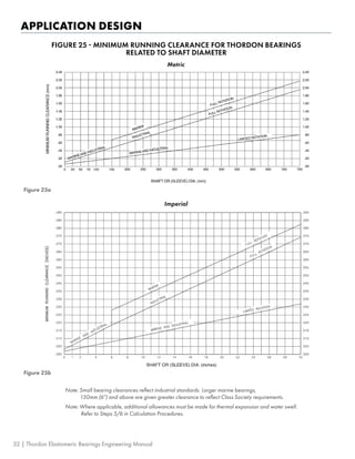
j) MINIMIZING INITIAL INSTALLED
CLEARANCE
Initial installed clearance for Thordon bearings is usually
larger than final running clearance, mainly because
the initial clearance includes absorption and thermal
expansion allowances. These allowances will disappear
during operation of the equipment, but this will take time.
In some applications, there is a requirement to keep the
initial installed clearance as small as possible. A typical
example would be a vertical pump bearing. Final running
clearance may be acceptable, but when absorption
allowance, thermal expansion and tolerance build-up
are considered, the accumulated initial clearance may be
beyond design requirements. In such cases it is necessary
to consider ways to reduce the initial clearance.
There are several options:
1. Thinner bearing - Absorption and thermal expansion
both vary according to the wall thickness of the bearing.
By reducing the wall thickness, the allowances for
these factors become smaller, so the initial clearance
is reduced. Reducing the wall thickness is usually
accomplished by reducing the housing diameter. The
Thordon Bearing Sizing Calculation program can be
useful in this exercise – it calculates “Minimum Installed
Clearance”. It can be used to determine what wall
thickness will yield the required initial clearance. The
wall may become too thin for an interference fit, so
bonding may be required.
2. Minimize bore closure variations – The bore closure
calculation (effect of interference on the I.D. of the
bearing) is the least precise aspect of the Thordon
dimension calculations. Actual bore closure will depend
on a number of factors including machined finish on
the bearing and housing. There are several ways to
minimize variations in bore closure:
a. Reducing the length/diameter ratio of the bearing will
reduce variations in bore closure over the length.
b. Final machining of the bearing bore after it is installed.
Machining after fitting into the housing eliminates
the effect of bore closure because it has already
happened. It also eliminates the effect of tolerance
build-up on the bearing wall. This method however
removes stressed material that is developing the “grip”
of the bearing within its housing so only minimum
material must be removed.
• For ungrooved bearings, this machining stage must
not remove more than 5% of the wall thickness.
• For grooved bearings, it is not as important
because the bore material is much less stressed.
However, machining should be limited to 10% of the
wall thickness or 25% of the groove depth, whichever
is less. Lubrication grooves must always be machined
before fitting the bearing into the housing.
c. Fitting the bearing into a dummy housing before
machining the I.D. This method is a variation of “b”
above which can be used when it is not practical to
install the bearing in its final housing for I.D. machining.
The dummy housing should have the exact dimensions
and machining finish as the final housing. This
method is less precise because it does not eliminate
machining tolerance variations on the housing. The
same restrictions on the amount of material that can
be removed mentioned in “b” above still apply.
22 | Thordon Elastomeric Bearings Engineering Manual](https://image.slidesharecdn.com/engineeringmanual-220906201519-44ac3b9f/85/engineering_manual-pdf-25-320.jpg)


![APPLICATION DESIGN
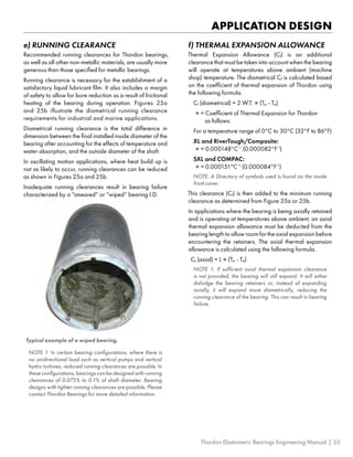
When freeze fitting a Thordon
bearing, the selection of a suitable
cooling agent depends on the
temperature differential for which
the bearing’s interference fit is
designed. [Temperature differential
is the difference between ambient
machine shop temperature and the
coldest temperature to which the
installed bearing will be exposed
during operation.] If the differential
is 40°C (100°F) or less, then dry
ice can be used. If the differential is
greater than 40°C (100°F), the use
of Liquid Nitrogen is recommended.
The amount of shrinkage that can be
expected can be estimated using the
following information:
• Each 10°C decrease in
temperature will result in an
approximate decrease in
diameter of 0.0014mm/mm of
diameter.
• Each 10°F decrease in
temperature will result in an
approximate decrease in
diameter of 0.0008 inches/inch
of diameter.
• On the removal of an
interference fit bearing from the
housing, it will recover a portion
of its total deflection almost
immediately, and then it will
slowly recover the balance of
the interference except for the
compression set portion. In tests,
recovery based on standard
interference is over 90% of
initial deflection over a period of
several weeks.
NOTE: Interference fit is not
recommended for Thordon HPSXL.
This material should be bonded in
place.
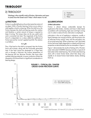
NOTE:
These
tests
were
conducted
using
a
bearing
with
a
shape
factor
of
4.
FIGURE
21
-
HOUSING
INTERFERENCE:
XL
BEARINGS
Figure
21a
Figure
21b
Imperial
Metric
28 | Thordon Elastomeric Bearings Engineering Manual](https://image.slidesharecdn.com/engineeringmanual-220906201519-44ac3b9f/85/engineering_manual-pdf-31-320.jpg)


![BONDING
c) ADHESIVE CURING
Provided the material was mixed correctly, the cure time
for TG-75 is dependent upon the temperature during the
curing period. The recommended curing temperatures for
TG-75 are:
• Typical: 20 to 40°C (68 to 104°F)
• Minimum: 10°C (50°F)
Contact Thordon Bearings if TG-75 is being used at
temperatures outside the range shown above.
Curing Times and Temperature
Over 60% of the bond strength is attained in 8 hours at
23°C (73°F). Approximately 80% of the bond strength is
achieved in 4 hours at 40°C (104°F). Full cure is reached
in 5 days at 23°C (73°F).
Insufficient curing time, particularly at low temperatures,
prior to water immersion will result in reduced bond strength
values. Water will stop further curing of the adhesive.
Note: For bearings with large OD [250mm (9.4843 in) and
up], it is important to machine the bearing AND perform
the bonding installation at approximately the SAME
temperature. Machining the bearing at one temperature
and installing it at a different temperature may have
significant effects on the optimal adhesive thickness – see
example.
After application of adhesive, keep bearing and carrier
assembly at a constant temperature while the adhesive
cures.
EXAMPLE
An SXL bearing is machined in the afternoon at 30°C
(86°F) to suit a housing ID of 250mm (9.843 in). Based on
optimal adhesive thickness, the bearing OD is machined to
250mm - 2 x 0.25mm = 249.50mm
(9.843 in - 2 x 0.010 in = 9.823 in.)
The bearing is to be installed the next day but note that the
shop temperature has increased to 35°C (95°F).
Using the thermal coefficient of expansion for SXL
[21.1 x 10⁻⁵
cm/cm/°C (11.7 x 10⁻⁵
in/in/°F)] and the
temperature difference [5°C (9°F)], the bearing OD at
35°C has increased to 249.76mm (9.833 in.)
The adhesive thickness is reduced to 0.12mm (0.005 in.)
with the temperature difference. Such thermal effects are
even greater with larger bearings.
d) ADHESIVE APPLICATION
As mentioned previously, for best results it is recommended
toconductthebondinginstallationattheSAMEtemperature
at which the bearing was machined. In cold weather
environments, it is important to maintain the temperature
above 10°C (50°F) for proper curing of the adhesive.
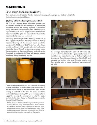
i) Split Bearings or Flat Surfaces
a. Apply the adhesive to the prepared surface of the metal
and spread evenly with a spatula or a small notched
trowel. See Figures 39 and 40.
Figure 39: Adhesive being applied to split metal housing
Figure 40: TG-75 being applied to OD of split SXL bearing
b. Position the Thordon component and clamp so that
a small amount of the adhesive is extruded out from
the edges of the Thordon part. See Figure 41. Do not
machine or handle the bonded piece for a minimum of
8 hours at 23°C or 73°F. Avoid smearing the adhesive
during assembly.
Figure 41: Clamping with slight force SXL to metal
housing
Thordon Elastomeric Bearings Engineering Manual | 53](https://image.slidesharecdn.com/engineeringmanual-220906201519-44ac3b9f/85/engineering_manual-pdf-56-320.jpg)


