Downloaded 33 times


![* % CT Effectiveness = Range X 100
* Rated % CT Effectiveness = 100 * (43 – 33) / (43 –
27.5)
= 64.5%
* Cooling Duty Handled/Cell in kCal = 1565 * 6.4 * 103
(i.e., Flow * Temperature Difference in kCal/hr.) = 10016 * 103 kCal/hr. (Rated
18750 * 103 kCal/hr.)
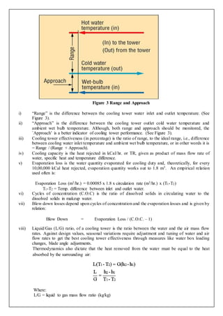
* Evaporation Losses in m3/hr. = 0.00085 x 1.8 x circulation rate
(m3/hr.) x (T1-T2)
= 0.00085 x 1.8 x 1565 x (44-
37.6)
= 15.32 m3/hr. per cell
* Percentage Evaporation Loss = [15.32/1565]*100
= 0.97%
* Blow down requirement for site COC of 2.7 = Evaporation losses / (COC–1)
= 15.32/(2.7–1) per cell i.e.,
9.01 m3/hr.
* Make up water requirement/cell in m3/hr. = Evaporation Loss + Blow down
Loss
= 15.32 + 9.01
= 24.33
Comments
Cooling water flow per cell is much lower, almost by 16.5%, need to investigate CW pump and system
performance for improvements. Increasing CW flow through cell was identified as a key result area for
improving performance of cooling towers.
Flow stratification in 3 cooling tower cells identified.
Algae growth identified in 6 cooling tower cells.
Cooling tower fans are of GRP type drawing 36.2 kW average. Replacement by efficient hollow FRP fan
blades is recommended.
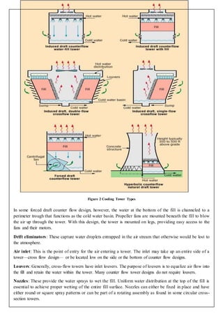
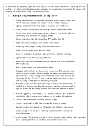
IV. Flow Control Strategies
Control of tower air flow can be done by varying methods: starting and stopping (On-off) of fans, use of
two- or three-speed fan motors, use of automatically adjustable pitch fans, and use of variable speed fans.
On-off fan operation of single speed fans provides the least effective control. Two-speed fans provide better
control with further improvement shown with three speed fans.
Automatic adjustable pitch fans and variable-speed fans can provide even closer control of tower cold-water
temperature. In multi-cell towers, fans in adjacent cells may be running at different speeds or some may be](https://image.slidesharecdn.com/140490105001-06mto-2oep-170411204724/85/Cooling-Tower-15-320.jpg)
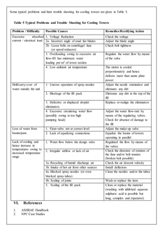

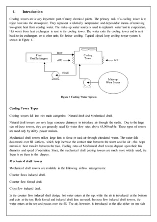
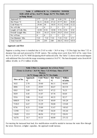
This document is a report on cooling towers submitted by a group of 5 chemical engineering students at the Gujarat Technological University. It provides an introduction to cooling towers, describing their main components and functions. It discusses the key parameters for evaluating cooling tower performance, including range, approach, effectiveness, cooling capacity, and evaporation loss. The primary goal of cooling towers is to reject heat from cooling water circuits into the atmosphere through evaporation.


