SlideShare a Scribd company logo
1 of 12
Download to read offline
1
1. INTRODUCTION
1.1 Cooling Tower
A cooling tower is a specialized heat exchanger in which air and water are brought
into direct contact with each other in order to reduce the water's temperature. As this
occurs, a small volume of water is evaporated, reducing the temperature of the water
being circulated through the tower.
Water, which has been heated by an industrial process or in an air-conditioning condenser, is pumped to the
cooling tower through pipes. The water sprays through nozzles onto banks of material called "fill," which slows
the flow of water through the cooling tower, and exposes as much water surface area as possible for maximum
air-water contact. As the water flows through the cooling tower, it is exposed to air, which is being pulled
through the tower by the electric motor-driven fan.
Figure 1. Schematic diagram of a cooling water system
CALCULATION
APPROACH = Cold water temperature – wet bulb temperature
= 35oC-25oC
=10oC
RANGE= Hot water temperature- cold water temperature
=42oC-35oC
=7oC
COOLING TOWER EFFICIENCY= Range/ (range+ approach)*100
=7oC/ (7oC+10oC)*100
=41.17%
TABLE 2 Key Technical Specifications
Sr. No. Parameter Units CT
2
1 Type of cooling tower Induced Draft
counter flow type
2 Water flow L/Hr 3800
3 Pumping Power W 40
4 Pumping Head m 1.52
5 Fan Power W 65
TABLE 3 Cooling Power Performance
Sr. No. Parameter Reference Units CT
1 Dry bulb temperature C 36*
2 Wet bulb temperature C 25*
3 CT inlet temperature C 42*
4 CT outlet temperature C 35*
5 Range C 7*
6 Approach C 10*
7 CT efficiency 41.17%
TABLE 4 Bill of Material
Sr. No. PRODUCT COST (Rs)
1 Frame (mild steel) 1200
2 Cooling Tower Casing (FRP) 850
3 Cooling Fan 1500
4 Water Pump 350
5 Fills 500
6 Heater 350
7 Electric Panel Board 300
8 Air Filter 200
9 Pipe connection 700
10 Tin sheet 100
11 Other stuff 300
TOTAL 6350
Tower materials
Originally, cooling towers were constructed primarily with wood, including the frame, casing,
louvers, fill and cold-water basin. Sometimes the cold-water basin was made of concrete. Today,
3
manufacturers use a variety of materials to construct cooling towers. Materials are chosen to
enhance corrosion resistance, reduce maintenance, and promote reliability and long service life.
Galvanized steel, various grades of stainless steel, glass fiber, and concrete are widely used in
tower construction, as well as aluminum and plastics for some components.
Frame and casing. Wooden towers are still available, but many components are made of different
materials, such as the casing around the wooden framework of glass fiber, the inlet air louvers of
glass fiber, the fill of plastic and the cold-water basin of steel. Many towers (casings and basins)
are constructed of galvanized steel or, where a corrosive atmosphere is a problem, the tower and/or
the basis are made of stainless steel. Larger towers sometimes are made of concrete. Glass fiber is
also widely used for cooling tower casings and basins, because they extend the life of the cooling
tower and provide protection against harmful chemicals.
Figure 2 frame of cooling tower
4
Figure 3 cooling tower casing
Fill. Plastics are widely used for fill, including PVC, polypropylene, and other polymers. When
water conditions require the use of splash fill, treated wood splash fill is still used in wooden
towers, but plastic splash fill is also widely used. Because of greater heat transfer efficiency, film
fill is chosen for applications where the circulating water is generally free of debris that could block
the fill passageways.
Figure 4 Fills
Nozzles. Plastics are also widely used for nozzles. Many nozzles are made of PVC, ABS,
polypropylene, and glass-filled nylon.
Figure 5 Nozzle
Fans. Aluminum, glass fiber and hot-dipped galvanized steel are commonly used fan materials.
Centrifugal fans are often fabricated from galvanized steel. Propeller fans are made from galvanized
steel, aluminum, or molded glass fiber reinforced plastic.
5
Figure 6 cooling fan
2.2 Mechanical draft cooling tower
Mechanical draft towers have large fans to force or draw air through circulated water. The water
falls downwards over fill surfaces, which help increase the contact time between the water and the
air - this helps maximize heat transfer between the two. Cooling rates of mechanical draft towers
depend upon various parameters such as fan diameter and speed of operation, fills for system
resistance etc. Mechanical draft towers are available in a large range of capacities. Towers can be
either factory built or field erected - for example concrete towers are only field erected. Many
towers are constructed so that they can be grouped together to achieve the desired capacity. Thus,
many cooling towers are assemblies of two or more individual cooling towers or "cells." The
number of cells they have, e.g., a eight-cell tower, often refers to such towers. Multiple-cell towers
can be lineal, square, or round depending upon the shape of the individual cells and whether the
air inlets are located on the sides or bottoms of the cells. The three types of mechanical draft towers
are summarized in (Table 1).
Figure 9. Induced draft counter flow cooling tower
6
Figure 10. Induced draft cross flow cooling tower
3. ASSESSMENT OF COOLING TOWERS
This section describes how the performance of cooling powers can be assessed. The
performance of cooling towers is evaluated to assess present levels of approach and range against
their design values, identify areas of energy wastage and to suggest improvements.
During the performance evaluation, portable monitoring instruments are used to measure the
following parameters:
■ Wet bulb temperature of air
■ Dry bulb temperature of air
■ Cooling tower inlet water temperature
■ Cooling tower outlet water temperature
■ Exhaust air temperature
■ Electrical readings of pump and fan motors
■ Water flow rate
■ Air flow rate
These measured parameters and then used to determine the cooling tower performance in
several ways. (Note: CT = cooling tower; CW = cooling water). These are:
a) Range (see Figure 7). This is the difference between the cooling tower water inlet and outlet
temperature. A high CT Range means that the cooling tower has been able to reduce the
water temperature effectively, and is thus performing well. The formula is:
CT Range (°C) = [CW inlet temp (°C) - CW outlet temp (°C)]
b) Approach (see Figure 7). This is the difference between the cooling tower outlet cold water
temperature and ambient wet bulb temperature. The lower the approach the better the cooling
tower performance. Although, both range and approach should be monitored, the ' Approach' is
a better indicator of cooling tower performance.
7
CT Approach (°C) = [CW outlet temp (°C) - Wet bulb temp (°C)]
c) Effectiveness. This is the ratio between the range and the ideal range (in percentage), i.e.
difference between cooling water inlet temperature and ambient wet bulb temperature, or in
other words it is = Range / (Range + Approach). The higher this ratio, the higher the cooling
tower effectiveness.
CT Effectiveness (%) = 100 x (CW temp - CW out temp) / (CW in temp - WB temp)
d) Cooling capacity. This is the heat rejected in kCal/hr or TR, given as product of mass flow rate
of water, specific heat and temperature difference.
e) Evaporation loss. This is the water quantity evaporated for cooling duty. Theoretically
the evaporation quantity works out to 1.8 m3 for every 1,000,000 kCal heat rejected. The
following formula can be used (Perry):
Evaporation loss (m3
/hr) = 0.00085 x 1.8 x circulation rate (m3
/hr) x (T1-T2) T1 - T2 =
temperature difference between inlet and outlet water
f) Cycles of concentration (C.O.C). This is the ratio of dissolved solids in circulating water to the
dissolved solids in makeup water.
g) Blow down losses depend upon cycles of concentration and the evaporation losses and is given
by formula:
Blow down = Evaporation loss / (C.O.C. - 1)
h) Liquid/Gas (L/G) ratio. The L/G ratio of a cooling tower is the ratio between the water and
the air mass flow rates. Cooling towers have certain design values, but seasonal variations
require adjustment and tuning of water and air flow rates to get the best cooling tower
effectiveness. Adjustments can be made by water box loading changes or blade angle
adjustments. Thermodynamic rules also dictate that the heat removed from the water must be
equal to the heat absorbed by the surrounding air. Therefore the following formulae can be used:
i) L (T1 - T2) = G (h2 - h1) L/G = (h2 - h1) / (T1 - T2)
Where:
L/G = liquid to gas mass flow ratio (kg/kg)
T1 = hot water temperature (°C)
T2 = cold-water temperature (°C) h2 = enthalpy of air-water vapor mixture at exhaust wet-
bulb temperature (same units as above)
h1 = enthalpy of air-water vapor mixture at inlet wet-bulb temperature.
4. ENERGY EFFICIENCY OPPORTUNITIES
This section includes main areas for improving energy efficiency of cooling towers. The main areas
for energy conservation include:
■ Selecting the right cooling tower (because the structural aspects of the cooling tower cannot
8
8
be changed after it is installed)
■
■ Fills
■ Pumps and water distribution system
■ Fans and motors
4.1 Selecting the right cooling towers
Once a cooling tower is in place it is very difficult to significantly improve its energy
performance. A number of factors are of influence on the cooling tower's performance and should
be considered when choosing a cooling tower: capacity, range, approach, heat load, wet bulb
temperature, and the relationship between these factors. This is described below.
4.1.1Capacity
Heat dissipation (in kCal/hour) and circulated flow rate (m3
/hr) are an indication of the capacity
of cooling towers. However, these design parameters are not sufficient to understand the cooling
tower performance. For example, a cooling tower sized to cool 4540 m3
/hr through a 13.9 °C
range might be larger than a cooling tower to cool 4540 m3
/hr through 19.5 °C range. Therefore
other design parameters are also needed.
4.1.2Range
Range is determined not by the cooling tower, but by the process it is serving. The range at the
exchanger is determined entirely by the heat load and the water circulation rate through the
exchanger and going to the cooling water. The range is a function of the heat load and the flow
circulated through the system:
Range °C = Heat load (in kCal/hour) / Water circulation rate (l/hour)
Cooling towers are usually specified to cool a certain flow rate from one temperature to another
temperature at a certain wet bulb temperature. For example, the cooling tower might be specified
to cool 4540 m3
/hr from 48.9°C to 32.2°C at 26.7°C wet bulb temperature.
4.1.3Approach
As a general rule, the closer the approach to the wet bulb, the more expensive the cooling tower
due to increased size. Usually a 2.8°C approach to the design wet bulb is the coldest water
temperature that cooling tower manufacturers will guarantee. When the size of the tower has to
be chosen, then the approach is most important, closely followed by the flow rate, and the range
and wet bulb would be of lesser importance.
Approach (5.5°C) = Cold-water temperature 32.2 °C - Wet bulb temperature (26.7°)
4.1.4Heat load
The heat load imposed on a cooling tower is determined by the process being served. The degree
of cooling required is controlled by the desired operating temperature of the process. In most
cases, a low operating temperature is desirable to increase process efficiency or to improve the
quality or quantity of the product. However, in some applications (e.g. internal combustion
9
engines) high operating temperatures are desirable. The size and cost of the cooling tower is
increases with increasing heat load. Purchasing undersized equipment (if the calculated heat load is
too low) and oversized equipment (if the calculated heat load is too high) is something to be aware
of Process heat loads may vary considerably depending upon the process involved and are
therefore difficult to determine accurately. On the other hand, air conditioning and
refrigeration heat loads can be determined with greater accuracy.
4.1.5Wet bulb temperature
Wet bulb temperature is an important factor in performance of evaporative water cooling
equipment, because it is the lowest temperature to which water can be cooled. For this reason, the
wet bulb temperature of the air entering the cooling tower determines the minimum operating
temperature level throughout the plant, process, or system. The following should be considered
when pre-selecting a cooling tower based on the wet bulb temperature:
Theoretically, a cooling tower will cool water to the entering wet bulb temperature. In practice,
however, water is cooled to a temperature higher than the wet bulb temperature because heat needs
to be rejected from the cooling tower.
■ A pre-selection of towers based on the design wet bulb temperature must consider
conditions at the tower site. The design wet bulb temperature also should not be
exceeded for more than 5 percent of the time. In general, the design temperature selected is
close to the average maximum wet bulb temperature in summer.
■ Confirm whether the wet bulb temperature is specified as ambient (the temperature in the
cooling tower area) or inlet (the temperature of the air entering the tower, which is often
affected by discharge vapors recycled into the tower). As the impact of recirculation
cannot be known in advance, the ambient wet bulb temperature is preferred.
■ Confirm with the supplier if the cooling tower is able to deal with the effects of
increased wet bulb temperatures.
4.2 Fill media effects
In a cooling tower, hot water is distributed above fill media and is cooled down through
evaporation as it flows down the tower and gets in contact with air. The fill media impacts energy
consumption in two ways:
■ Electricity is used for pumping above the fill and for fans that create the air draft. An
efficiently designed fill media with appropriate water distribution, drift eliminator, fan,
gearbox and motor with therefore lead to lower electricity consumption.
■ Heat exchange between air and water is influenced by surface area of heat exchange,
duration of heat exchange (interaction) and turbulence in water effecting thoroughness of
intermixing. The fill media determines all of these and therefore in fluences the heat
exchange. The greater the heat exchange, the more effective the cooling tower becomes. There
are three types of fills:
10
Splash fills media. Splash fill media generates the required heat exchange area by
splashing water over the fill media into smaller water droplets. The surface area of the water
droplets is the surface area for heat exchange with the air.
Film fills media. In a film fill, water forms a thin film on either side of fill sheets. The
surface area of the fill sheets is the area for heat exchange with the surrounding air. Film fill
can result in significant electricity savings due to fewer air and pumping head
requirements.
Low-clog film fills. Low-clog film fills with higher flute sizes were recently developed to
handle high turbid waters. Low clog film fills are considered as the best choice for seawater
in terms of power savings and performance compared to conventional splash type fills.
4.3 Pumps and water distribution
Pumps
Areas for energy efficiency improvements are discussed in details in the Pumps and Pumping
Systems chapter.
Figure 11 Water Pump
Optimize cooling water treatment
Cooling water treatment (e.g. to control suspended solids, algae growth) is mandatory for any
cooling tower independent of what fill media is used. With increasing costs of water, efforts to
increase Cycles of Concentration (COC), by cooling water treatment would help to reduce make
up water requirements significantly. In large industries and power plants improving the COC is
often considered a key area for water conservation.
Install drift eliminators
It is very difficult to ignore drift problems in cooling towers. Nowadays most of the end user
specifications assume a 0.02% drift loss.
But thanks to technological developments and the production of PVC, manufacturers have
improved drift eliminator designs. As a result drift losses can now be as low as 0.003 -
0.001%.
11
4.4 Cooling tower fans
The purpose of a cooling tower fan is to move a specified quantity of air through the system. The
fan has to overcome the system resistance, which is defined as the pressure loss, to move the air.
The fan output or work done by the fan is the product of air flow and the pressure loss. The fan
output and kW input determines the fan efficiency. The fan efficiency in turn is greatly dependent
on the profile of the blade. Blades include:
■ Metallic blades, which are manufactured by extrusion or casting processes and therefore it is
difficult to produce ideal aerodynamic profiles
■ Fiber reinforced plastic (FRP) blades are normally hand molded which makes it easier to
produce an optimum aerodynamic profile tailored to specific duty conditions. Because FRP
fans are light, they need a low starting torque requiring a lower HP motor, the lives of the gear
box, motor and bearing is increased, and maintenance is easier. 85-92% efficiency can be
achieved with blades with an aerodynamic profile, optimum twist, taper and a high
coefficient of lift to coefficient of drop ratio. However, this efficiency is drastically affected
by factors such as tip clearance, obstacles to airflow and inlet shape, etc.
5. OPTION CHECKLIST
This section lists the most important options to improve energy efficiency of cooling towers.
■ Follow manufacturer's recommended clearances around cooling towers and relocate or
modify structures that interfere with the air intake or exhaust
■ Optimize cooling tower fan blade angle on a seasonal and/or load basis
■ Correct excessive and/or uneven fan blade tip clearance and poor fan balance
■ In old counter-flow cooling towers, replace old spray type nozzles with new square spray
nozzles that do not clog
■ Replace splash bars with self-extinguishing PVC cellular film fill
■ Install nozzles that spray in a more uniform water pattern
■ Clean plugged cooling tower distribution nozzles regularly
■ Balance flow to cooling tower hot water basins
■ Cover hot water basins to minimize algae growth that contributes to fouling
■ Optimize the blow down flow rate, taking into account the cycles of concentration (COC) limit.
■ Replace slat type drift eliminators with low-pressure drop, self-extinguishing PVC cellular
units.
■ Restrict flows through large loads to design values.
12
12
■ Keep the cooling water temperature to a minimum level by (a) segregating high heat loads
like furnaces, air compressors, DG sets and (b) isolating cooling towers from sensitive
applications like A/C plants, condensers of captive power plant etc. Note: A1°Ccooling water
temperature increase may increase the A/C compressor electricity consumption by 2.7%. A
1°C drop in cooling water temperature can give a heat rate saving of 5 k Cal/kWh in a
thermal power plant.
■ Monitor approach, effectiveness and cooling capacity to continuously optimize the cooling
tower performance, but consider seasonal variations and side variations.
■ Monitor liquid to gas ratio and cooling water flow rates and amend these depending on the
design values and seasonal variations. For example: increase water loads during summer
and times when approach is high and increase air flow during monsoon times and when approach
is low.
■ Consider COC improvement measures for water savings
■ Consider energy efficient fiber reinforced plastic blade adoption for fan energy savings
■ Control cooling tower fans based on exit water temperatures especially in small units
■ Check cooling water pumps regularly to maximize their efficiency.
8. Conclusion:
First we concerned the meaning of cooling tower and knew each one how to use it, how it is installed,
and from which materials it is prepared.
Then identified the main two types of cooling tower and recognized the series of work of each one and its
uses.
Then the evaluation of the cooling tower work and how to increase the energy efficiency opportunities
have been discussed.
By an effective list we knew how to check the work of cooling tower.
It is very difficult to achieve higher efficiency with small prototype.
SUBMITTED TO: SUBMITTED BY:
ER. ANIL BHARTI AMIT KUMAR (1414514)
ER. SAMIR TIWARI HARSHAL RANA (1414520)
NARINDER MEHRA (1414522)

More Related Content

What's hot

cooling towers system .pdf
cooling towers system .pdfcooling towers system .pdf
cooling towers system .pdfKarnav Rana
 
A complete presentation on Boiler.
A complete presentation on Boiler.A complete presentation on Boiler.
A complete presentation on Boiler.Anuj Maurya
 
Design options for hvac distribution systems
Design options for hvac distribution systemsDesign options for hvac distribution systems
Design options for hvac distribution systemsJASON KEMBOI
 
Cooling towers
Cooling towersCooling towers
Cooling towersctlin5
 
Presentation cooling tower
Presentation cooling towerPresentation cooling tower
Presentation cooling towerALOK KUMAR SWAIN
 
Hvac systems presentation_slides
Hvac systems presentation_slidesHvac systems presentation_slides
Hvac systems presentation_slidesguy ygal
 
TYPES OF HEAT EXCHANGERS_Prefer02.pdf
TYPES OF HEAT EXCHANGERS_Prefer02.pdfTYPES OF HEAT EXCHANGERS_Prefer02.pdf
TYPES OF HEAT EXCHANGERS_Prefer02.pdfKAhmedRehman
 
DESIGN OF AIR PRE HEATER AND ECONOMIZER
DESIGN OF AIR PRE HEATER AND ECONOMIZERDESIGN OF AIR PRE HEATER AND ECONOMIZER
DESIGN OF AIR PRE HEATER AND ECONOMIZERGopi Chand
 
Water Conservation - Cooling Tower Management Overview
Water Conservation - Cooling Tower Management Overview Water Conservation - Cooling Tower Management Overview
Water Conservation - Cooling Tower Management Overview brentmwhite
 
Hvac for beginners
Hvac for beginnersHvac for beginners
Hvac for beginnersAmith singh
 

What's hot (20)

cooling towers system .pdf
cooling towers system .pdfcooling towers system .pdf
cooling towers system .pdf
 
cooling tower
cooling towercooling tower
cooling tower
 
Presentation on cooling tower
Presentation on cooling towerPresentation on cooling tower
Presentation on cooling tower
 
Cooling tower
Cooling towerCooling tower
Cooling tower
 
cooling tower
cooling tower cooling tower
cooling tower
 
cooling towers
 cooling towers cooling towers
cooling towers
 
A complete presentation on Boiler.
A complete presentation on Boiler.A complete presentation on Boiler.
A complete presentation on Boiler.
 
Design options for hvac distribution systems
Design options for hvac distribution systemsDesign options for hvac distribution systems
Design options for hvac distribution systems
 
Cooling towers
Cooling towersCooling towers
Cooling towers
 
Presentation cooling tower
Presentation cooling towerPresentation cooling tower
Presentation cooling tower
 
Distillation Basics(Done).ppt
Distillation Basics(Done).pptDistillation Basics(Done).ppt
Distillation Basics(Done).ppt
 
Chiller water systems
Chiller water systemsChiller water systems
Chiller water systems
 
Hvac systems presentation_slides
Hvac systems presentation_slidesHvac systems presentation_slides
Hvac systems presentation_slides
 
TYPES OF HEAT EXCHANGERS_Prefer02.pdf
TYPES OF HEAT EXCHANGERS_Prefer02.pdfTYPES OF HEAT EXCHANGERS_Prefer02.pdf
TYPES OF HEAT EXCHANGERS_Prefer02.pdf
 
Cooling tower
Cooling towerCooling tower
Cooling tower
 
DESIGN OF AIR PRE HEATER AND ECONOMIZER
DESIGN OF AIR PRE HEATER AND ECONOMIZERDESIGN OF AIR PRE HEATER AND ECONOMIZER
DESIGN OF AIR PRE HEATER AND ECONOMIZER
 
Boiler Introduction
Boiler IntroductionBoiler Introduction
Boiler Introduction
 
Water Conservation - Cooling Tower Management Overview
Water Conservation - Cooling Tower Management Overview Water Conservation - Cooling Tower Management Overview
Water Conservation - Cooling Tower Management Overview
 
Cooling tower
Cooling towerCooling tower
Cooling tower
 
Hvac for beginners
Hvac for beginnersHvac for beginners
Hvac for beginners
 

Similar to Cooling Tower Guide: Selection, Operation and Efficiency

Final report on spent solution in hydro
Final report on spent solution in hydroFinal report on spent solution in hydro
Final report on spent solution in hydroprateekj765
 
mini-cooling-tower
mini-cooling-towermini-cooling-tower
mini-cooling-towerKani Vel
 
Ppt-Cooling-Tower.pptx
Ppt-Cooling-Tower.pptxPpt-Cooling-Tower.pptx
Ppt-Cooling-Tower.pptxBijitBiswas5
 
Cooling Towers - An Extensive Approach
Cooling Towers - An Extensive ApproachCooling Towers - An Extensive Approach
Cooling Towers - An Extensive ApproachNoaman Ahmed
 
cooling tower, Factors Affecting Cooling Tower Performance,Efficient System O...
cooling tower, Factors Affecting Cooling Tower Performance,Efficient System O...cooling tower, Factors Affecting Cooling Tower Performance,Efficient System O...
cooling tower, Factors Affecting Cooling Tower Performance,Efficient System O...Salman Jailani
 
Spent solution in hydro
Spent solution in hydroSpent solution in hydro
Spent solution in hydroprateekj765
 
Energy Conservation Opportunities in Cooling Tower.pdf
Energy Conservation Opportunities in Cooling Tower.pdfEnergy Conservation Opportunities in Cooling Tower.pdf
Energy Conservation Opportunities in Cooling Tower.pdfNITIN ASNANI
 
Cooling of mine air by chilled water system (final)
Cooling of mine air by chilled water system (final)Cooling of mine air by chilled water system (final)
Cooling of mine air by chilled water system (final)Safdar Ali
 
Predicting and Optimising CT LWT
Predicting and Optimising CT LWTPredicting and Optimising CT LWT
Predicting and Optimising CT LWTRaji Panicker
 
2nd Revised FYP Reporting
2nd Revised FYP Reporting2nd Revised FYP Reporting
2nd Revised FYP ReportingBurhan Ahmed
 
Air refrigeration system by Bell Coleman cycle and Vortex tube
Air refrigeration system by Bell Coleman cycle and Vortex tubeAir refrigeration system by Bell Coleman cycle and Vortex tube
Air refrigeration system by Bell Coleman cycle and Vortex tubeaparnamalyala
 

Similar to Cooling Tower Guide: Selection, Operation and Efficiency (20)

Cooling tower
Cooling tower Cooling tower
Cooling tower
 
Final report on spent solution in hydro
Final report on spent solution in hydroFinal report on spent solution in hydro
Final report on spent solution in hydro
 
Cooling towers tech article v1r04
Cooling towers tech article v1r04Cooling towers tech article v1r04
Cooling towers tech article v1r04
 
mini-cooling-tower
mini-cooling-towermini-cooling-tower
mini-cooling-tower
 
final project.docx
final project.docxfinal project.docx
final project.docx
 
Ppt-Cooling-Tower.pptx
Ppt-Cooling-Tower.pptxPpt-Cooling-Tower.pptx
Ppt-Cooling-Tower.pptx
 
Cooling Towers - An Extensive Approach
Cooling Towers - An Extensive ApproachCooling Towers - An Extensive Approach
Cooling Towers - An Extensive Approach
 
Cooling Tower
Cooling TowerCooling Tower
Cooling Tower
 
3Ch7.pdf
3Ch7.pdf3Ch7.pdf
3Ch7.pdf
 
cooling tower, Factors Affecting Cooling Tower Performance,Efficient System O...
cooling tower, Factors Affecting Cooling Tower Performance,Efficient System O...cooling tower, Factors Affecting Cooling Tower Performance,Efficient System O...
cooling tower, Factors Affecting Cooling Tower Performance,Efficient System O...
 
final project1.docx
final project1.docxfinal project1.docx
final project1.docx
 
Spent solution in hydro
Spent solution in hydroSpent solution in hydro
Spent solution in hydro
 
AC end.pdf
AC end.pdfAC end.pdf
AC end.pdf
 
Energy Conservation Opportunities in Cooling Tower.pdf
Energy Conservation Opportunities in Cooling Tower.pdfEnergy Conservation Opportunities in Cooling Tower.pdf
Energy Conservation Opportunities in Cooling Tower.pdf
 
B013141316
B013141316B013141316
B013141316
 
Cooling Tower
Cooling TowerCooling Tower
Cooling Tower
 
Cooling of mine air by chilled water system (final)
Cooling of mine air by chilled water system (final)Cooling of mine air by chilled water system (final)
Cooling of mine air by chilled water system (final)
 
Predicting and Optimising CT LWT
Predicting and Optimising CT LWTPredicting and Optimising CT LWT
Predicting and Optimising CT LWT
 
2nd Revised FYP Reporting
2nd Revised FYP Reporting2nd Revised FYP Reporting
2nd Revised FYP Reporting
 
Air refrigeration system by Bell Coleman cycle and Vortex tube
Air refrigeration system by Bell Coleman cycle and Vortex tubeAir refrigeration system by Bell Coleman cycle and Vortex tube
Air refrigeration system by Bell Coleman cycle and Vortex tube
 

Recently uploaded

Decoding Kotlin - Your guide to solving the mysterious in Kotlin.pptx
Decoding Kotlin - Your guide to solving the mysterious in Kotlin.pptxDecoding Kotlin - Your guide to solving the mysterious in Kotlin.pptx
Decoding Kotlin - Your guide to solving the mysterious in Kotlin.pptxJoão Esperancinha
 
Biology for Computer Engineers Course Handout.pptx
Biology for Computer Engineers Course Handout.pptxBiology for Computer Engineers Course Handout.pptx
Biology for Computer Engineers Course Handout.pptxDeepakSakkari2
 
Study on Air-Water & Water-Water Heat Exchange in a Finned Tube Exchanger
Study on Air-Water & Water-Water Heat Exchange in a Finned Tube ExchangerStudy on Air-Water & Water-Water Heat Exchange in a Finned Tube Exchanger
Study on Air-Water & Water-Water Heat Exchange in a Finned Tube ExchangerAnamika Sarkar
 
HARMONY IN THE NATURE AND EXISTENCE - Unit-IV
HARMONY IN THE NATURE AND EXISTENCE - Unit-IVHARMONY IN THE NATURE AND EXISTENCE - Unit-IV
HARMONY IN THE NATURE AND EXISTENCE - Unit-IVRajaP95
 
(ANVI) Koregaon Park Call Girls Just Call 7001035870 [ Cash on Delivery ] Pun...
(ANVI) Koregaon Park Call Girls Just Call 7001035870 [ Cash on Delivery ] Pun...(ANVI) Koregaon Park Call Girls Just Call 7001035870 [ Cash on Delivery ] Pun...
(ANVI) Koregaon Park Call Girls Just Call 7001035870 [ Cash on Delivery ] Pun...ranjana rawat
 
CCS355 Neural Network & Deep Learning UNIT III notes and Question bank .pdf
CCS355 Neural Network & Deep Learning UNIT III notes and Question bank .pdfCCS355 Neural Network & Deep Learning UNIT III notes and Question bank .pdf
CCS355 Neural Network & Deep Learning UNIT III notes and Question bank .pdfAsst.prof M.Gokilavani
 
Current Transformer Drawing and GTP for MSETCL
Current Transformer Drawing and GTP for MSETCLCurrent Transformer Drawing and GTP for MSETCL
Current Transformer Drawing and GTP for MSETCLDeelipZope
 
SPICE PARK APR2024 ( 6,793 SPICE Models )
SPICE PARK APR2024 ( 6,793 SPICE Models )SPICE PARK APR2024 ( 6,793 SPICE Models )
SPICE PARK APR2024 ( 6,793 SPICE Models )Tsuyoshi Horigome
 
Artificial-Intelligence-in-Electronics (K).pptx
Artificial-Intelligence-in-Electronics (K).pptxArtificial-Intelligence-in-Electronics (K).pptx
Artificial-Intelligence-in-Electronics (K).pptxbritheesh05
 
Sachpazis Costas: Geotechnical Engineering: A student's Perspective Introduction
Sachpazis Costas: Geotechnical Engineering: A student's Perspective IntroductionSachpazis Costas: Geotechnical Engineering: A student's Perspective Introduction
Sachpazis Costas: Geotechnical Engineering: A student's Perspective IntroductionDr.Costas Sachpazis
 
Past, Present and Future of Generative AI
Past, Present and Future of Generative AIPast, Present and Future of Generative AI
Past, Present and Future of Generative AIabhishek36461
 
Sheet Pile Wall Design and Construction: A Practical Guide for Civil Engineer...
Sheet Pile Wall Design and Construction: A Practical Guide for Civil Engineer...Sheet Pile Wall Design and Construction: A Practical Guide for Civil Engineer...
Sheet Pile Wall Design and Construction: A Practical Guide for Civil Engineer...Dr.Costas Sachpazis
 
VIP Call Girls Service Kondapur Hyderabad Call +91-8250192130
VIP Call Girls Service Kondapur Hyderabad Call +91-8250192130VIP Call Girls Service Kondapur Hyderabad Call +91-8250192130
VIP Call Girls Service Kondapur Hyderabad Call +91-8250192130Suhani Kapoor
 
What are the advantages and disadvantages of membrane structures.pptx
What are the advantages and disadvantages of membrane structures.pptxWhat are the advantages and disadvantages of membrane structures.pptx
What are the advantages and disadvantages of membrane structures.pptxwendy cai
 
High Profile Call Girls Nagpur Isha Call 7001035870 Meet With Nagpur Escorts
High Profile Call Girls Nagpur Isha Call 7001035870 Meet With Nagpur EscortsHigh Profile Call Girls Nagpur Isha Call 7001035870 Meet With Nagpur Escorts
High Profile Call Girls Nagpur Isha Call 7001035870 Meet With Nagpur Escortsranjana rawat
 
CCS355 Neural Network & Deep Learning Unit II Notes with Question bank .pdf
CCS355 Neural Network & Deep Learning Unit II Notes with Question bank .pdfCCS355 Neural Network & Deep Learning Unit II Notes with Question bank .pdf
CCS355 Neural Network & Deep Learning Unit II Notes with Question bank .pdfAsst.prof M.Gokilavani
 
power system scada applications and uses
power system scada applications and usespower system scada applications and uses
power system scada applications and usesDevarapalliHaritha
 

Recently uploaded (20)

Decoding Kotlin - Your guide to solving the mysterious in Kotlin.pptx
Decoding Kotlin - Your guide to solving the mysterious in Kotlin.pptxDecoding Kotlin - Your guide to solving the mysterious in Kotlin.pptx
Decoding Kotlin - Your guide to solving the mysterious in Kotlin.pptx
 
Biology for Computer Engineers Course Handout.pptx
Biology for Computer Engineers Course Handout.pptxBiology for Computer Engineers Course Handout.pptx
Biology for Computer Engineers Course Handout.pptx
 
Study on Air-Water & Water-Water Heat Exchange in a Finned Tube Exchanger
Study on Air-Water & Water-Water Heat Exchange in a Finned Tube ExchangerStudy on Air-Water & Water-Water Heat Exchange in a Finned Tube Exchanger
Study on Air-Water & Water-Water Heat Exchange in a Finned Tube Exchanger
 
HARMONY IN THE NATURE AND EXISTENCE - Unit-IV
HARMONY IN THE NATURE AND EXISTENCE - Unit-IVHARMONY IN THE NATURE AND EXISTENCE - Unit-IV
HARMONY IN THE NATURE AND EXISTENCE - Unit-IV
 
(ANVI) Koregaon Park Call Girls Just Call 7001035870 [ Cash on Delivery ] Pun...
(ANVI) Koregaon Park Call Girls Just Call 7001035870 [ Cash on Delivery ] Pun...(ANVI) Koregaon Park Call Girls Just Call 7001035870 [ Cash on Delivery ] Pun...
(ANVI) Koregaon Park Call Girls Just Call 7001035870 [ Cash on Delivery ] Pun...
 
CCS355 Neural Network & Deep Learning UNIT III notes and Question bank .pdf
CCS355 Neural Network & Deep Learning UNIT III notes and Question bank .pdfCCS355 Neural Network & Deep Learning UNIT III notes and Question bank .pdf
CCS355 Neural Network & Deep Learning UNIT III notes and Question bank .pdf
 
🔝9953056974🔝!!-YOUNG call girls in Rajendra Nagar Escort rvice Shot 2000 nigh...
🔝9953056974🔝!!-YOUNG call girls in Rajendra Nagar Escort rvice Shot 2000 nigh...🔝9953056974🔝!!-YOUNG call girls in Rajendra Nagar Escort rvice Shot 2000 nigh...
🔝9953056974🔝!!-YOUNG call girls in Rajendra Nagar Escort rvice Shot 2000 nigh...
 
Current Transformer Drawing and GTP for MSETCL
Current Transformer Drawing and GTP for MSETCLCurrent Transformer Drawing and GTP for MSETCL
Current Transformer Drawing and GTP for MSETCL
 
SPICE PARK APR2024 ( 6,793 SPICE Models )
SPICE PARK APR2024 ( 6,793 SPICE Models )SPICE PARK APR2024 ( 6,793 SPICE Models )
SPICE PARK APR2024 ( 6,793 SPICE Models )
 
Artificial-Intelligence-in-Electronics (K).pptx
Artificial-Intelligence-in-Electronics (K).pptxArtificial-Intelligence-in-Electronics (K).pptx
Artificial-Intelligence-in-Electronics (K).pptx
 
Sachpazis Costas: Geotechnical Engineering: A student's Perspective Introduction
Sachpazis Costas: Geotechnical Engineering: A student's Perspective IntroductionSachpazis Costas: Geotechnical Engineering: A student's Perspective Introduction
Sachpazis Costas: Geotechnical Engineering: A student's Perspective Introduction
 
Past, Present and Future of Generative AI
Past, Present and Future of Generative AIPast, Present and Future of Generative AI
Past, Present and Future of Generative AI
 
Sheet Pile Wall Design and Construction: A Practical Guide for Civil Engineer...
Sheet Pile Wall Design and Construction: A Practical Guide for Civil Engineer...Sheet Pile Wall Design and Construction: A Practical Guide for Civil Engineer...
Sheet Pile Wall Design and Construction: A Practical Guide for Civil Engineer...
 
VIP Call Girls Service Kondapur Hyderabad Call +91-8250192130
VIP Call Girls Service Kondapur Hyderabad Call +91-8250192130VIP Call Girls Service Kondapur Hyderabad Call +91-8250192130
VIP Call Girls Service Kondapur Hyderabad Call +91-8250192130
 
Exploring_Network_Security_with_JA3_by_Rakesh Seal.pptx
Exploring_Network_Security_with_JA3_by_Rakesh Seal.pptxExploring_Network_Security_with_JA3_by_Rakesh Seal.pptx
Exploring_Network_Security_with_JA3_by_Rakesh Seal.pptx
 
What are the advantages and disadvantages of membrane structures.pptx
What are the advantages and disadvantages of membrane structures.pptxWhat are the advantages and disadvantages of membrane structures.pptx
What are the advantages and disadvantages of membrane structures.pptx
 
High Profile Call Girls Nagpur Isha Call 7001035870 Meet With Nagpur Escorts
High Profile Call Girls Nagpur Isha Call 7001035870 Meet With Nagpur EscortsHigh Profile Call Girls Nagpur Isha Call 7001035870 Meet With Nagpur Escorts
High Profile Call Girls Nagpur Isha Call 7001035870 Meet With Nagpur Escorts
 
CCS355 Neural Network & Deep Learning Unit II Notes with Question bank .pdf
CCS355 Neural Network & Deep Learning Unit II Notes with Question bank .pdfCCS355 Neural Network & Deep Learning Unit II Notes with Question bank .pdf
CCS355 Neural Network & Deep Learning Unit II Notes with Question bank .pdf
 
young call girls in Rajiv Chowk🔝 9953056974 🔝 Delhi escort Service
young call girls in Rajiv Chowk🔝 9953056974 🔝 Delhi escort Serviceyoung call girls in Rajiv Chowk🔝 9953056974 🔝 Delhi escort Service
young call girls in Rajiv Chowk🔝 9953056974 🔝 Delhi escort Service
 
power system scada applications and uses
power system scada applications and usespower system scada applications and uses
power system scada applications and uses
 

Cooling Tower Guide: Selection, Operation and Efficiency

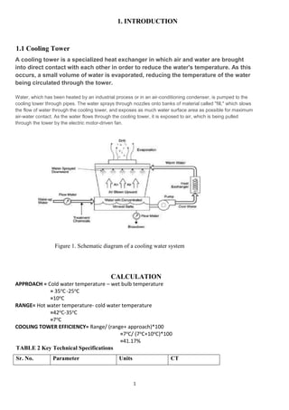
  • 1. 1 1. INTRODUCTION 1.1 Cooling Tower A cooling tower is a specialized heat exchanger in which air and water are brought into direct contact with each other in order to reduce the water's temperature. As this occurs, a small volume of water is evaporated, reducing the temperature of the water being circulated through the tower. Water, which has been heated by an industrial process or in an air-conditioning condenser, is pumped to the cooling tower through pipes. The water sprays through nozzles onto banks of material called "fill," which slows the flow of water through the cooling tower, and exposes as much water surface area as possible for maximum air-water contact. As the water flows through the cooling tower, it is exposed to air, which is being pulled through the tower by the electric motor-driven fan. Figure 1. Schematic diagram of a cooling water system CALCULATION APPROACH = Cold water temperature – wet bulb temperature = 35oC-25oC =10oC RANGE= Hot water temperature- cold water temperature =42oC-35oC =7oC COOLING TOWER EFFICIENCY= Range/ (range+ approach)*100 =7oC/ (7oC+10oC)*100 =41.17% TABLE 2 Key Technical Specifications Sr. No. Parameter Units CT
  • 2. 2 1 Type of cooling tower Induced Draft counter flow type 2 Water flow L/Hr 3800 3 Pumping Power W 40 4 Pumping Head m 1.52 5 Fan Power W 65 TABLE 3 Cooling Power Performance Sr. No. Parameter Reference Units CT 1 Dry bulb temperature C 36* 2 Wet bulb temperature C 25* 3 CT inlet temperature C 42* 4 CT outlet temperature C 35* 5 Range C 7* 6 Approach C 10* 7 CT efficiency 41.17% TABLE 4 Bill of Material Sr. No. PRODUCT COST (Rs) 1 Frame (mild steel) 1200 2 Cooling Tower Casing (FRP) 850 3 Cooling Fan 1500 4 Water Pump 350 5 Fills 500 6 Heater 350 7 Electric Panel Board 300 8 Air Filter 200 9 Pipe connection 700 10 Tin sheet 100 11 Other stuff 300 TOTAL 6350 Tower materials Originally, cooling towers were constructed primarily with wood, including the frame, casing, louvers, fill and cold-water basin. Sometimes the cold-water basin was made of concrete. Today,
  • 3. 3 manufacturers use a variety of materials to construct cooling towers. Materials are chosen to enhance corrosion resistance, reduce maintenance, and promote reliability and long service life. Galvanized steel, various grades of stainless steel, glass fiber, and concrete are widely used in tower construction, as well as aluminum and plastics for some components. Frame and casing. Wooden towers are still available, but many components are made of different materials, such as the casing around the wooden framework of glass fiber, the inlet air louvers of glass fiber, the fill of plastic and the cold-water basin of steel. Many towers (casings and basins) are constructed of galvanized steel or, where a corrosive atmosphere is a problem, the tower and/or the basis are made of stainless steel. Larger towers sometimes are made of concrete. Glass fiber is also widely used for cooling tower casings and basins, because they extend the life of the cooling tower and provide protection against harmful chemicals. Figure 2 frame of cooling tower
  • 4. 4 Figure 3 cooling tower casing Fill. Plastics are widely used for fill, including PVC, polypropylene, and other polymers. When water conditions require the use of splash fill, treated wood splash fill is still used in wooden towers, but plastic splash fill is also widely used. Because of greater heat transfer efficiency, film fill is chosen for applications where the circulating water is generally free of debris that could block the fill passageways. Figure 4 Fills Nozzles. Plastics are also widely used for nozzles. Many nozzles are made of PVC, ABS, polypropylene, and glass-filled nylon. Figure 5 Nozzle Fans. Aluminum, glass fiber and hot-dipped galvanized steel are commonly used fan materials. Centrifugal fans are often fabricated from galvanized steel. Propeller fans are made from galvanized steel, aluminum, or molded glass fiber reinforced plastic.
  • 5. 5 Figure 6 cooling fan 2.2 Mechanical draft cooling tower Mechanical draft towers have large fans to force or draw air through circulated water. The water falls downwards over fill surfaces, which help increase the contact time between the water and the air - this helps maximize heat transfer between the two. Cooling rates of mechanical draft towers depend upon various parameters such as fan diameter and speed of operation, fills for system resistance etc. Mechanical draft towers are available in a large range of capacities. Towers can be either factory built or field erected - for example concrete towers are only field erected. Many towers are constructed so that they can be grouped together to achieve the desired capacity. Thus, many cooling towers are assemblies of two or more individual cooling towers or "cells." The number of cells they have, e.g., a eight-cell tower, often refers to such towers. Multiple-cell towers can be lineal, square, or round depending upon the shape of the individual cells and whether the air inlets are located on the sides or bottoms of the cells. The three types of mechanical draft towers are summarized in (Table 1). Figure 9. Induced draft counter flow cooling tower
  • 6. 6 Figure 10. Induced draft cross flow cooling tower 3. ASSESSMENT OF COOLING TOWERS This section describes how the performance of cooling powers can be assessed. The performance of cooling towers is evaluated to assess present levels of approach and range against their design values, identify areas of energy wastage and to suggest improvements. During the performance evaluation, portable monitoring instruments are used to measure the following parameters: ■ Wet bulb temperature of air ■ Dry bulb temperature of air ■ Cooling tower inlet water temperature ■ Cooling tower outlet water temperature ■ Exhaust air temperature ■ Electrical readings of pump and fan motors ■ Water flow rate ■ Air flow rate These measured parameters and then used to determine the cooling tower performance in several ways. (Note: CT = cooling tower; CW = cooling water). These are: a) Range (see Figure 7). This is the difference between the cooling tower water inlet and outlet temperature. A high CT Range means that the cooling tower has been able to reduce the water temperature effectively, and is thus performing well. The formula is: CT Range (°C) = [CW inlet temp (°C) - CW outlet temp (°C)] b) Approach (see Figure 7). This is the difference between the cooling tower outlet cold water temperature and ambient wet bulb temperature. The lower the approach the better the cooling tower performance. Although, both range and approach should be monitored, the ' Approach' is a better indicator of cooling tower performance.
  • 7. 7 CT Approach (°C) = [CW outlet temp (°C) - Wet bulb temp (°C)] c) Effectiveness. This is the ratio between the range and the ideal range (in percentage), i.e. difference between cooling water inlet temperature and ambient wet bulb temperature, or in other words it is = Range / (Range + Approach). The higher this ratio, the higher the cooling tower effectiveness. CT Effectiveness (%) = 100 x (CW temp - CW out temp) / (CW in temp - WB temp) d) Cooling capacity. This is the heat rejected in kCal/hr or TR, given as product of mass flow rate of water, specific heat and temperature difference. e) Evaporation loss. This is the water quantity evaporated for cooling duty. Theoretically the evaporation quantity works out to 1.8 m3 for every 1,000,000 kCal heat rejected. The following formula can be used (Perry): Evaporation loss (m3 /hr) = 0.00085 x 1.8 x circulation rate (m3 /hr) x (T1-T2) T1 - T2 = temperature difference between inlet and outlet water f) Cycles of concentration (C.O.C). This is the ratio of dissolved solids in circulating water to the dissolved solids in makeup water. g) Blow down losses depend upon cycles of concentration and the evaporation losses and is given by formula: Blow down = Evaporation loss / (C.O.C. - 1) h) Liquid/Gas (L/G) ratio. The L/G ratio of a cooling tower is the ratio between the water and the air mass flow rates. Cooling towers have certain design values, but seasonal variations require adjustment and tuning of water and air flow rates to get the best cooling tower effectiveness. Adjustments can be made by water box loading changes or blade angle adjustments. Thermodynamic rules also dictate that the heat removed from the water must be equal to the heat absorbed by the surrounding air. Therefore the following formulae can be used: i) L (T1 - T2) = G (h2 - h1) L/G = (h2 - h1) / (T1 - T2) Where: L/G = liquid to gas mass flow ratio (kg/kg) T1 = hot water temperature (°C) T2 = cold-water temperature (°C) h2 = enthalpy of air-water vapor mixture at exhaust wet- bulb temperature (same units as above) h1 = enthalpy of air-water vapor mixture at inlet wet-bulb temperature. 4. ENERGY EFFICIENCY OPPORTUNITIES This section includes main areas for improving energy efficiency of cooling towers. The main areas for energy conservation include: ■ Selecting the right cooling tower (because the structural aspects of the cooling tower cannot 8
  • 8. 8 be changed after it is installed) ■ ■ Fills ■ Pumps and water distribution system ■ Fans and motors 4.1 Selecting the right cooling towers Once a cooling tower is in place it is very difficult to significantly improve its energy performance. A number of factors are of influence on the cooling tower's performance and should be considered when choosing a cooling tower: capacity, range, approach, heat load, wet bulb temperature, and the relationship between these factors. This is described below. 4.1.1Capacity Heat dissipation (in kCal/hour) and circulated flow rate (m3 /hr) are an indication of the capacity of cooling towers. However, these design parameters are not sufficient to understand the cooling tower performance. For example, a cooling tower sized to cool 4540 m3 /hr through a 13.9 °C range might be larger than a cooling tower to cool 4540 m3 /hr through 19.5 °C range. Therefore other design parameters are also needed. 4.1.2Range Range is determined not by the cooling tower, but by the process it is serving. The range at the exchanger is determined entirely by the heat load and the water circulation rate through the exchanger and going to the cooling water. The range is a function of the heat load and the flow circulated through the system: Range °C = Heat load (in kCal/hour) / Water circulation rate (l/hour) Cooling towers are usually specified to cool a certain flow rate from one temperature to another temperature at a certain wet bulb temperature. For example, the cooling tower might be specified to cool 4540 m3 /hr from 48.9°C to 32.2°C at 26.7°C wet bulb temperature. 4.1.3Approach As a general rule, the closer the approach to the wet bulb, the more expensive the cooling tower due to increased size. Usually a 2.8°C approach to the design wet bulb is the coldest water temperature that cooling tower manufacturers will guarantee. When the size of the tower has to be chosen, then the approach is most important, closely followed by the flow rate, and the range and wet bulb would be of lesser importance. Approach (5.5°C) = Cold-water temperature 32.2 °C - Wet bulb temperature (26.7°) 4.1.4Heat load The heat load imposed on a cooling tower is determined by the process being served. The degree of cooling required is controlled by the desired operating temperature of the process. In most cases, a low operating temperature is desirable to increase process efficiency or to improve the quality or quantity of the product. However, in some applications (e.g. internal combustion
  • 9. 9 engines) high operating temperatures are desirable. The size and cost of the cooling tower is increases with increasing heat load. Purchasing undersized equipment (if the calculated heat load is too low) and oversized equipment (if the calculated heat load is too high) is something to be aware of Process heat loads may vary considerably depending upon the process involved and are therefore difficult to determine accurately. On the other hand, air conditioning and refrigeration heat loads can be determined with greater accuracy. 4.1.5Wet bulb temperature Wet bulb temperature is an important factor in performance of evaporative water cooling equipment, because it is the lowest temperature to which water can be cooled. For this reason, the wet bulb temperature of the air entering the cooling tower determines the minimum operating temperature level throughout the plant, process, or system. The following should be considered when pre-selecting a cooling tower based on the wet bulb temperature: Theoretically, a cooling tower will cool water to the entering wet bulb temperature. In practice, however, water is cooled to a temperature higher than the wet bulb temperature because heat needs to be rejected from the cooling tower. ■ A pre-selection of towers based on the design wet bulb temperature must consider conditions at the tower site. The design wet bulb temperature also should not be exceeded for more than 5 percent of the time. In general, the design temperature selected is close to the average maximum wet bulb temperature in summer. ■ Confirm whether the wet bulb temperature is specified as ambient (the temperature in the cooling tower area) or inlet (the temperature of the air entering the tower, which is often affected by discharge vapors recycled into the tower). As the impact of recirculation cannot be known in advance, the ambient wet bulb temperature is preferred. ■ Confirm with the supplier if the cooling tower is able to deal with the effects of increased wet bulb temperatures. 4.2 Fill media effects In a cooling tower, hot water is distributed above fill media and is cooled down through evaporation as it flows down the tower and gets in contact with air. The fill media impacts energy consumption in two ways: ■ Electricity is used for pumping above the fill and for fans that create the air draft. An efficiently designed fill media with appropriate water distribution, drift eliminator, fan, gearbox and motor with therefore lead to lower electricity consumption. ■ Heat exchange between air and water is influenced by surface area of heat exchange, duration of heat exchange (interaction) and turbulence in water effecting thoroughness of intermixing. The fill media determines all of these and therefore in fluences the heat exchange. The greater the heat exchange, the more effective the cooling tower becomes. There are three types of fills:
  • 10. 10 Splash fills media. Splash fill media generates the required heat exchange area by splashing water over the fill media into smaller water droplets. The surface area of the water droplets is the surface area for heat exchange with the air. Film fills media. In a film fill, water forms a thin film on either side of fill sheets. The surface area of the fill sheets is the area for heat exchange with the surrounding air. Film fill can result in significant electricity savings due to fewer air and pumping head requirements. Low-clog film fills. Low-clog film fills with higher flute sizes were recently developed to handle high turbid waters. Low clog film fills are considered as the best choice for seawater in terms of power savings and performance compared to conventional splash type fills. 4.3 Pumps and water distribution Pumps Areas for energy efficiency improvements are discussed in details in the Pumps and Pumping Systems chapter. Figure 11 Water Pump Optimize cooling water treatment Cooling water treatment (e.g. to control suspended solids, algae growth) is mandatory for any cooling tower independent of what fill media is used. With increasing costs of water, efforts to increase Cycles of Concentration (COC), by cooling water treatment would help to reduce make up water requirements significantly. In large industries and power plants improving the COC is often considered a key area for water conservation. Install drift eliminators It is very difficult to ignore drift problems in cooling towers. Nowadays most of the end user specifications assume a 0.02% drift loss. But thanks to technological developments and the production of PVC, manufacturers have improved drift eliminator designs. As a result drift losses can now be as low as 0.003 - 0.001%.
  • 11. 11 4.4 Cooling tower fans The purpose of a cooling tower fan is to move a specified quantity of air through the system. The fan has to overcome the system resistance, which is defined as the pressure loss, to move the air. The fan output or work done by the fan is the product of air flow and the pressure loss. The fan output and kW input determines the fan efficiency. The fan efficiency in turn is greatly dependent on the profile of the blade. Blades include: ■ Metallic blades, which are manufactured by extrusion or casting processes and therefore it is difficult to produce ideal aerodynamic profiles ■ Fiber reinforced plastic (FRP) blades are normally hand molded which makes it easier to produce an optimum aerodynamic profile tailored to specific duty conditions. Because FRP fans are light, they need a low starting torque requiring a lower HP motor, the lives of the gear box, motor and bearing is increased, and maintenance is easier. 85-92% efficiency can be achieved with blades with an aerodynamic profile, optimum twist, taper and a high coefficient of lift to coefficient of drop ratio. However, this efficiency is drastically affected by factors such as tip clearance, obstacles to airflow and inlet shape, etc. 5. OPTION CHECKLIST This section lists the most important options to improve energy efficiency of cooling towers. ■ Follow manufacturer's recommended clearances around cooling towers and relocate or modify structures that interfere with the air intake or exhaust ■ Optimize cooling tower fan blade angle on a seasonal and/or load basis ■ Correct excessive and/or uneven fan blade tip clearance and poor fan balance ■ In old counter-flow cooling towers, replace old spray type nozzles with new square spray nozzles that do not clog ■ Replace splash bars with self-extinguishing PVC cellular film fill ■ Install nozzles that spray in a more uniform water pattern ■ Clean plugged cooling tower distribution nozzles regularly ■ Balance flow to cooling tower hot water basins ■ Cover hot water basins to minimize algae growth that contributes to fouling ■ Optimize the blow down flow rate, taking into account the cycles of concentration (COC) limit. ■ Replace slat type drift eliminators with low-pressure drop, self-extinguishing PVC cellular units. ■ Restrict flows through large loads to design values. 12
  • 12. 12 ■ Keep the cooling water temperature to a minimum level by (a) segregating high heat loads like furnaces, air compressors, DG sets and (b) isolating cooling towers from sensitive applications like A/C plants, condensers of captive power plant etc. Note: A1°Ccooling water temperature increase may increase the A/C compressor electricity consumption by 2.7%. A 1°C drop in cooling water temperature can give a heat rate saving of 5 k Cal/kWh in a thermal power plant. ■ Monitor approach, effectiveness and cooling capacity to continuously optimize the cooling tower performance, but consider seasonal variations and side variations. ■ Monitor liquid to gas ratio and cooling water flow rates and amend these depending on the design values and seasonal variations. For example: increase water loads during summer and times when approach is high and increase air flow during monsoon times and when approach is low. ■ Consider COC improvement measures for water savings ■ Consider energy efficient fiber reinforced plastic blade adoption for fan energy savings ■ Control cooling tower fans based on exit water temperatures especially in small units ■ Check cooling water pumps regularly to maximize their efficiency. 8. Conclusion: First we concerned the meaning of cooling tower and knew each one how to use it, how it is installed, and from which materials it is prepared. Then identified the main two types of cooling tower and recognized the series of work of each one and its uses. Then the evaluation of the cooling tower work and how to increase the energy efficiency opportunities have been discussed. By an effective list we knew how to check the work of cooling tower. It is very difficult to achieve higher efficiency with small prototype. SUBMITTED TO: SUBMITTED BY: ER. ANIL BHARTI AMIT KUMAR (1414514) ER. SAMIR TIWARI HARSHAL RANA (1414520) NARINDER MEHRA (1414522)