SlideShare a Scribd company logo
1 of 25
Download to read offline
TechnischeUniversität Chemnitz
Chair of Measurement and Sensor Technology
Prof. Dr.-Ing. OlfaKanoun
1 | P a g e
Department of Electrical Engineering and Information
Technology
Chair of Measurement and Sensor Technology
“Controlling and optimization of 3D optical stage for precise
movement”
Project Lab Embedded Systems
Group: 13
Members: AvadhutKhade
Vinay Venu
Yash Inaniya
Supervisor: Ammar Al-Hamry
Date: 24/6/2017
TechnischeUniversität Chemnitz
Chair of Measurement and Sensor Technology
Prof. Dr.-Ing. OlfaKanoun
2 | P a g e
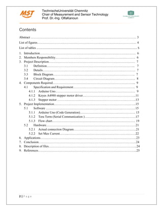
Contents
Abstract ……………………………………………………………………………………… 3
List of figures………………………………………………………………………………… 4
List of tables ………………………………………………………………………………………………………………………………….. 5
1. Introduction……………………………………………………………………………… 6
2. Members Responsibility………………………………………………………………… 6
3. Project Description……………………………………………………………………… 7
3.1 Definition……………………………………………………………………….. 7
3.2 Details…………………………………………………………………………… 7
3.3 Block Diagram………………………………………………………………….. 7
3.4 Circuit Diagram…………………………………………………………………. 8
4. Components Required…………………………………………………………………... 9
4.1 Specification and Requirement…………………………………………………. 9
4.1.1 Arduino Uno………………………………………………………………… 9
4.1.2 Keyes A4988 stepper motor driver…………………………………………..11
4.1.3 Stepper motor ………………………………………………………………..13
5. Project Implementation…………………………………………………………………..15
5.1 Software …………………………………………………………………………15
5.1.1 Arduino Uno (Code Generation)……………………………………………. 15
5.1.2 Tera Term (Serial Communication )…………………………………………17
5.1.3 Flow chart…………………………………………………………………… 19
5.2 Hardware…………………………………………………………………………21
5.2.1 Actual connection Diagram…………………………………………………..21
5.2.2 Set Max Current……...………………………………………………………22
6. Applications………………………………………………………………………………23
7. Conclusion………………………………………………………………………………..24
8. Description of files………………………………………………………………………..24
9. References………………………………………………………………………………...25
TechnischeUniversität Chemnitz
Chair of Measurement and Sensor Technology
Prof. Dr.-Ing. OlfaKanoun
3 | P a g e
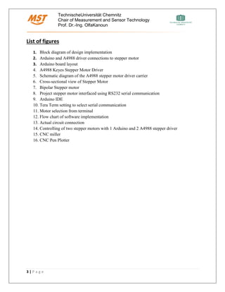
List of figures
1. Block diagram of design implementation
2. Arduino and A4988 driver connections to stepper motor
3. Arduino board layout
4. A4988 Keyes Stepper Motor Driver
5. Schematic diagram of the A4988 stepper motor driver carrier
6. Cross-sectional view of Stepper Motor
7. Bipolar Stepper motor
8. Project stepper motor interfaced using RS232 serial communication
9. Arduino IDE
10. Tera Term setting to select serial communication
11. Motor selection from terminal
12. Flow chart of software implementation
13. Actual circuit connection
14. Controlling of two stepper motors with 1 Arduino and 2 A4988 stepper driver
15. CNC miller
16. CNC Pen Plotter
TechnischeUniversität Chemnitz
Chair of Measurement and Sensor Technology
Prof. Dr.-Ing. OlfaKanoun
4 | P a g e
List of Tables
1. Pin description of Arduino Uno
2. Operating voltage range of A4988
TechnischeUniversität Chemnitz
Chair of Measurement and Sensor Technology
Prof. Dr.-Ing. OlfaKanoun
5 | P a g e
Abstract
Stepper motor has been quite popular in Industrial Automation and Robotics. It’s simple working
principle and operation has made its usage inevitable in areas relating to control and positioning.
Computer controlled stepper motor are in high demand as they provide precise positioning and
thus lay down the ground for our project where we implement control of stepper motor using
Arduino Uno.
TechnischeUniversität Chemnitz
Chair of Measurement and Sensor Technology
Prof. Dr.-Ing. OlfaKanoun
6 | P a g e
1.Introduction
In today’s Industrial automation and robotics, whenever we want to control the position of an
instrument according to our requirements, stepper motor is the easiest solution available. Stepper
motor, a DC electric motor rotates in the form of number of equal steps. The motor position can
be controlled and be hold at particular step which helps us to get the precise position we want to
achieve. Due to its advantage of precise positioning, speed control and low speed torque, stepper
motor has found its usage in several application like 3D Printer, Camera Platforms and X, Y
plotters.
With the advent of Arduino microcontroller boards, it is easy to control the stepper motor in
desired steps. Stepper motor has been quite popular in robotics due to their ability to move in
steps .The advantage of these motors is that they can be made to response using digital input
which in turn makes it easy to control and less costly.
2. Members Responsibilities
Members Responsibilities
Avadhut Khade • Circuit designing
• Hardware components research
• RS232 configuration
• Presentation
Vinay Venu • Software Implementation
• Source code development
• Stepper motor Analysis
• Presentation
Yash Inaniya • Circuit Designing
• Debugging/Source code optimization
• Signal tapping
• Report
TechnischeUniversität Chemnitz
Chair of Measurement and Sensor Technology
Prof. Dr.-Ing. OlfaKanoun
7 | P a g e
3. Project Description
3.1 Definition
Controlling of two stepper motors mounted on the microscope instrument for x-y direction using
an Arduino Uno board and stepper motor driver. Precise positioning of Laser through the
microscope to focus on the miniature sensor.
3.2 Details
As the project requires precise focus of the laser beam, it can be realized by controlling of the
stepper motor mounted on the microscope instrument through which the laser is passing. The
simplest way to do that is with Arduino Uno. Arduino Uno has inbuilt library for stepper motor
and thus can be easily applied for controlling stepper motor. The output of stepper motor is a
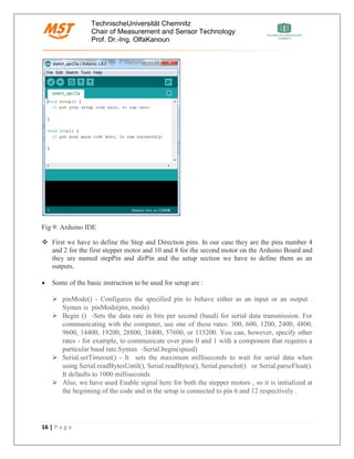
RS232 serial communication cable which is interfaced with the Keyes A4988 stepper driver
board. The stepper driver board is the central communication device here and will vary the
voltage to keep a constant current across the stepper motor. The driver also provides the required
step resolutions in five different types and thus can be suited for different positioning.
The software part is implemented through Arduino which also sends signal to the driver as to
how many steps the motor should run. The value of the number of steps is input through the
terminal and accordingly the motor is selected for either X positioning or Y positioning.
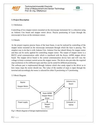
3.3 Block Diagram
Fig 1: Block diagram of design implementation
Keyes A4988
Stepper Motor
Driver
Bipolar
Stepper Motor
Arduino Uno
Board
Power supply Computer or
laptopStepper
Motor
TechnischeUniversität Chemnitz
Chair of Measurement and Sensor Technology
Prof. Dr.-Ing. OlfaKanoun
8 | P a g e
3.4 Circuit Diagram
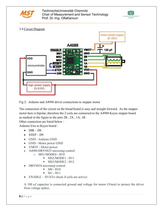
Fig 2: Arduino and A4988 driver connections to stepper motor
The connection of the circuit on the bread board is easy and straight forward. As the stepper
motor here is bipolar, therefore the 2 coils are connected to the A4988 Keyes stepper board
as marked in the figure to the pins 2B , 2A , 1A, 1B .
Other connection are listed below :
Arduino Uno to Keyes board :
• DIR – D8
• STEP – D9
• GND - Arduino GND
• GND - Motor power GND
• VMOT - Motor power
• A4988/DRV8825 microstep control
o MS1/MODE0 - D10
▪ MS2/MODE1 - D11
▪ MS3/MODE2 - D12
• DRV8834 microstep control
▪ M0 - D10
▪ M1 - D11
• ENABLE - D13(To check if coils are active)
A 100 µf capacitor is connected ground and voltage for motor (Vmot) to protect the driver
from voltage spikes.
TechnischeUniversität Chemnitz
Chair of Measurement and Sensor Technology
Prof. Dr.-Ing. OlfaKanoun
9 | P a g e
4. Components Required
• Arduino Uno board
• 2 Bipolar Stepper motor
• Keyes A4988 Stepper Motor Driver
• 100 µf Capacitor
• 12 DC Power supply
• Connecting / Hook-up / Jump wires
• A breadboard
4.1 Component specification
The technical specification of the components used is specified here :
4.1.1 Arduino Uno
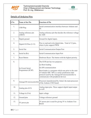
Arduino is an open-source prototyping platform based on an easy-to-use hardware and
software.Arduino UNO (Fig 3) is a microcontroller board based on ATMega328P. It has 14
digital input/output pins (6 can be used as PWM outputs) and 6 analog inputs (description in
Table). The 16 MHz quartz crystal controls the timing and clock of the UNO board. The
communications to the UNO board is through the USB cable which powers the board as well.
A separate power jack is provided for remote applications. The operating voltage of the UNO
board is 5V. It has 2 KB SRAM and 32 KB Flash memory. The board can be programmed
using Arduino IDE software and the hex code can directly be flashed to the board without
any external programming devices
Fig 3: Arduino Uno Board
TechnischeUniversität Chemnitz
Chair of Measurement and Sensor Technology
Prof. Dr.-Ing. OlfaKanoun
10 | P a g e
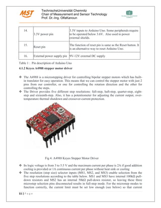
Details of Arduino Pins
S No Name of the Pin Function of Pin
1.
USB Plug
Serial communication interface between Arduino and
PC
2. Analog reference pin
(AREF)
Analog reference pin that decides the reference voltage
for ADC
3. Digital ground Ground for digital inputs.
4.
Digital I/O Pins (2-13)
Pins to read and write digital data. Total of 12 pins,
where 6 pins support PWM
5. Serial Out Serial Communication Output Port
6. Serial In (Rx) Serial Communication Input Port
7. Reset Button Hardware Reset. The button with the highest priority.
8.
In-Circuit Serial
Programmer (ICSP)
The ICSP pin has two purposes:
(a) Boot-loading
(b) SPI communication
Boot-loader is a program which runs prior to the start
of Arduino IDE. SPI is a serial synchronous data
protocol used by the Atmega328 microcontroller to
communicate with peripheral devices
9.
Atmega328 microcontroller
Processor manufactured by Atmel, the main processor
of the Arduino UNO board
10.
Analog pins (0-5)
Analog input pins. These support digital input/output
as well.
11. Voltage in (Vin) Input voltage
12. Ground pins Voltage reference ground
13.
5V power pin
5V power pin is used for giving 5V to Arduino Uno
Board
TechnischeUniversität Chemnitz
Chair of Measurement and Sensor Technology
Prof. Dr.-Ing. OlfaKanoun
11 | P a g e
Table 1 : Pin description of Arduino Uno
4.1.2 Keyes A4988 stepper motor driver
❖ The A4988 is a microstepping driver for controlling bipolar stepper motors which has built-
in translator for easy operation. This means that we can control the stepper motor with just 2
pins from our controller, or one for controlling the rotation direction and the other for
controlling the steps.
❖ The Driver provides five different step resolutions: full-step, haft-step, quarter-step, eight-
step and sixteenth-step. Also, it has a potentiometer for adjusting the current output, over-
temperature thermal shutdown and crossover-current protection.
Fig 4: A4988 Keyes Stepper Motor Driver
❖ Its logic voltage is from 3 to 5.5 V and the maximum current per phase is 2A if good addition
cooling is provided or 1A continuous current per phase without heat sink or cooling
❖ The resolution (step size) selector inputs (MS1, MS2, and MS3) enable selection from the
five step resolutions according to the table below. MS1 and MS3 have internal 100kΩ pull-
down resistors and MS2 has an internal 50kΩ pull-down resistor, so leaving these three
microstep selection pins disconnected results in full-step mode. For the microstep modes to
function correctly, the current limit must be set low enough (see below) so that current
14.
3.3V power pin
3.3V inputs to Arduino Uno. Some peripherals require
to be operated below 3.6V. Also used to power
external shields.
15.
Reset pin
The function of reset pin is same as the Reset button. It
is an alternative way to reset Arduino Uno.
16. External power supply pin 9V-12V external DC supply
TechnischeUniversität Chemnitz
Chair of Measurement and Sensor Technology
Prof. Dr.-Ing. OlfaKanoun
12 | P a g e
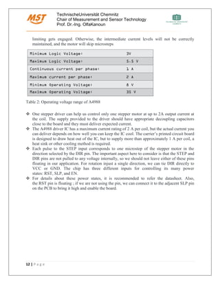
limiting gets engaged. Otherwise, the intermediate current levels will not be correctly
maintained, and the motor will skip microsteps
Table 2: Operating voltage range of A4988
❖ One stepper driver can help us control only one stepper motor at up to 2A output current at
the coil. The supply provided to the driver should have appropriate decoupling capacitors
close to the board and they must deliver expected current.
❖ The A4988 driver IC has a maximum current rating of 2 A per coil, but the actual current you
can deliver depends on how well you can keep the IC cool. The carrier’s printed circuit board
is designed to draw heat out of the IC, but to supply more than approximately 1 A per coil, a
heat sink or other cooling method is required.
❖ Each pulse to the STEP input corresponds to one microstep of the stepper motor in the
direction selected by the DIR pin. The important aspect here to consider is that the STEP and
DIR pins are not pulled to any voltage internally, so we should not leave either of these pins
floating in our application. For rotation injust a single direction, we can tie DIR directly to
VCC or GND. The chip has three different inputs for controlling its many power
states: RST, SLP, and EN.
❖ For details about these power states, it is recommended to refer the datasheet. Also,
the RST pin is floating ; if we are not using the pin, we can connect it to the adjacent SLP pin
on the PCB to bring it high and enable the board.
TechnischeUniversität Chemnitz
Chair of Measurement and Sensor Technology
Prof. Dr.-Ing. OlfaKanoun
13 | P a g e
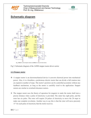
Schematic diagram
Fig 5: Schematic diagram of the A4988 stepper motor driver carrier
4.1.3Stepper motor
❖ A stepper motor is an electromechanical device it converts electrical power into mechanical
power. Also, it is a brushless, synchronous electric motor that can divide a full rotation into
an expansive number of steps. The motor’s position can be controlled accurately without any
feedback mechanism, as long as the motor is carefully sized to the application. Stepper
motors are similar to switched reluctance motors.
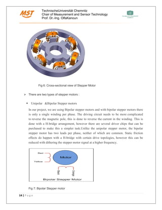
❖ The stepper motor uses the theory of operation for magnets to make the motor shaft turn a
precise distance when a pulse of electricity is provided. The stator has eight poles, and the
rotor has six poles. The rotor will require 24 pulses of electricity to move the 24 steps to
make one complete revolution. Another way to say this is that the rotor will move precisely
15° for each pulse of electricity that the motor receives.
TechnischeUniversität Chemnitz
Chair of Measurement and Sensor Technology
Prof. Dr.-Ing. OlfaKanoun
14 | P a g e
Fig 6: Cross-sectional view of Stepper Motor
➢ There are two types of stepper motors :
▪ Unipolar &Bipolar Stepper motors
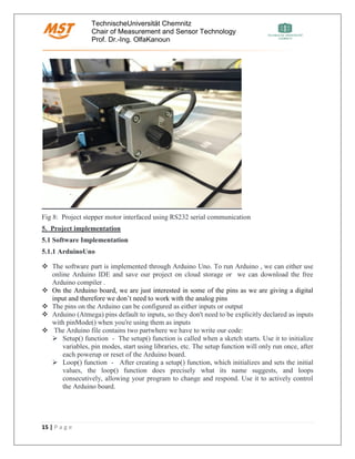
In our project, we are using Bipolar stepper motors and with bipolar stepper motors there
is only a single winding per phase. The driving circuit needs to be more complicated
to reverse the magnetic pole, this is done to reverse the current in the winding. This is
done with a H-bridge arrangement, however there are several driver chips that can be
purchased to make this a simpler task.Unlike the unipolar stepper motor, the bipolar
stepper motor has two leads per phase, neither of which are common. Static friction
effects do happen with a H-bridge with certain drive topologies, however this can be
reduced with dithering the stepper motor signal at a higher frequency.
Fig 7: Bipolar Stepper motor
TechnischeUniversität Chemnitz
Chair of Measurement and Sensor Technology
Prof. Dr.-Ing. OlfaKanoun
15 | P a g e
Fig 8: Project stepper motor interfaced using RS232 serial communication
5. Project implementation
5.1 Software Implementation
5.1.1 ArduinoUno
❖ The software part is implemented through Arduino Uno. To run Arduino , we can either use
online Arduino IDE and save our project on cloud storage or we can download the free
Arduino compiler .
❖ On the Arduino board, we are just interested in some of the pins as we are giving a digital
input and therefore we don’t need to work with the analog pins
❖ The pins on the Arduino can be configured as either inputs or output
❖ Arduino (Atmega) pins default to inputs, so they don't need to be explicitly declared as inputs
with pinMode() when you're using them as inputs
❖ The Arduino file contains two partwhere we have to write our code:
➢ Setup() function - The setup() function is called when a sketch starts. Use it to initialize
variables, pin modes, start using libraries, etc. The setup function will only run once, after
each powerup or reset of the Arduino board.
➢ Loop() function - After creating a setup() function, which initializes and sets the initial
values, the loop() function does precisely what its name suggests, and loops
consecutively, allowing your program to change and respond. Use it to actively control
the Arduino board.
TechnischeUniversität Chemnitz
Chair of Measurement and Sensor Technology
Prof. Dr.-Ing. OlfaKanoun
16 | P a g e
Fig 9: Arduino IDE
❖ First we have to define the Step and Direction pins. In our case they are the pins number 4
and 2 for the first stepper motor and 10 and 8 for the second motor on the Arduino Board and
they are named stepPin and dirPin and the setup section we have to define them as an
outputs.
• Some of the basic instruction to be used for setup are :
➢ pinMode() - Configures the specified pin to behave either as an input or an output .
Syntax is pinMode(pin, mode)
➢ Begin () -Sets the data rate in bits per second (baud) for serial data transmission. For
communicating with the computer, use one of these rates: 300, 600, 1200, 2400, 4800,
9600, 14400, 19200, 28800, 38400, 57600, or 115200. You can, however, specify other
rates - for example, to communicate over pins 0 and 1 with a component that requires a
particular baud rate.Syntax -Serial.begin(speed)
➢ Serial.setTimeout() - It sets the maximum milliseconds to wait for serial data when
using Serial.readBytesUntil(), Serial.readBytes(), Serial.parseInt() or Serial.parseFloat().
It defaults to 1000 milliseconds
➢ Also, we have used Enable signal here for both the stepper motors , so it is initialized at
the beginning of the code and in the setup is connected to pin 6 and 12 respectively .
TechnischeUniversität Chemnitz
Chair of Measurement and Sensor Technology
Prof. Dr.-Ing. OlfaKanoun
17 | P a g e
❖ Basic Instruction used for main body loop are :
➢ Println() - Prints data to the serial port as human-readable ASCII text. This command can
take many forms. Numbers are printed using an ASCII character for each digit. Floats are
similarly printed as ASCII digits, defaulting to two decimal places. Bytes are sent as a
single character. Characters and strings are sent as is .Syntax -Serial.printin(val)
➢ digitalWrite()- Write a HIGH or a LOW value to a digital pin.If the pin has been
configured as an OUTPUT with pinMode(), its voltage will be set to the corresponding
value: 5V (or 3.3V on 3.3V boards) for HIGH, 0V (ground) for LOW.If the pin is
configured as an INPUT, digitalWrite() will enable (HIGH) or disable (LOW) the
internal pullup on the input pin. It is recommended to set the pinMode()
to INPUT_PULLUP to enable the internal pull-up resistor.
➢ digitalRead() - Reads the value from a specified digital pin, either HIGH or LOW .
❖ In the loop section first we will set the Direction pin on high state that will enable the motor
to move in a particular direction. Now using this for loop we will make the motor make one
full cycle rotation. As the driver is set on Full Step Mode and our Stepper Motor has 1.8
degrees step angle, or 200 steps, we need to send 200 pulses into the Step Pin to make one
full cycle rotation. So the for loop will have 200 iterations and each time it will set the Step
pin on high and then low state for making the pulses. Between each digitalWrite we need add
some delay from which the speed of the motor will depend.
❖ After this full cycle rotation we will make one second delay, then change the direction of
rotation by setting the dirPin on a low state and now make 2 full cycle rotations with this
loop of 400 iterations. At the end there is one more second delay. Now let’s upload the code
and see how it will work.
❖ For serial communication , there are different software available and in our project we have
used “Tera Term” software as terminal to give input value to the stepper motor .
5.1.2 Tera Term Software
• Tera Term (rarely TeraTerm) is an open-source, free, software implemented, terminal
emulator (communications) program. It emulates different types of computer terminals, from
DEC VT100 to DEC VT382
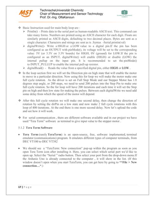
• We should see a “TeraTerm: New connection” pop-up within the program as soon as you
open Tera Term icon after installing it. Here, you can select which serial port we’d like to
open up. Select the “Serial ” radio button. Then select your port from the drop-down menu.If
the Ardunio Uno is already connected to the computer , it will show in the list. (If this
window doesn’t open when you start TeraTerm, you can get here by going to **File > New
connection…“.)
TechnischeUniversität Chemnitz
Chair of Measurement and Sensor Technology
Prof. Dr.-Ing. OlfaKanoun
18 | P a g e
Fig 10: Tera Term setting to select serial communication
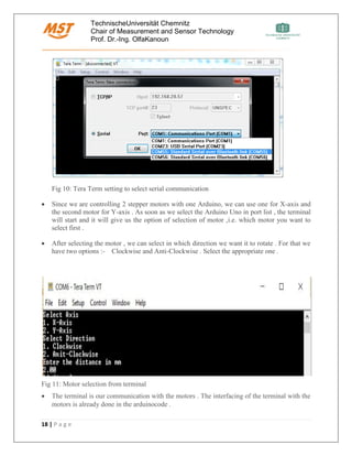
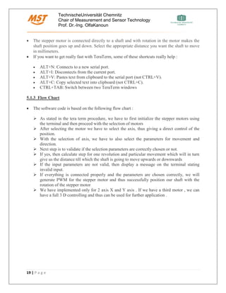
• Since we are controlling 2 stepper motors with one Arduino, we can use one for X-axis and
the second motor for Y-axis . As soon as we select the Arduino Uno in port list , the terminal
will start and it will give us the option of selection of motor ,i.e. which motor you want to
select first .
• After selecting the motor , we can select in which direction we want it to rotate . For that we
have two options :- Clockwise and Anti-Clockwise . Select the appropriate one .
Fig 11: Motor selection from terminal
• The terminal is our communication with the motors . The interfacing of the terminal with the
motors is already done in the arduinocode .
TechnischeUniversität Chemnitz
Chair of Measurement and Sensor Technology
Prof. Dr.-Ing. OlfaKanoun
19 | P a g e
• The stepper motor is connected directly to a shaft and with rotation in the motor makes the
shaft position goes up and down. Select the appropriate distance you want the shaft to move
in millimeters.
• If you want to get really fast with TeraTerm, some of these shortcuts really help :
• ALT+N: Connects to a new serial port.
• ALT+I: Disconnects from the current port.
• ALT+V: Pastes text from clipboard to the serial port (not CTRL+V).
• ALT+C: Copy selected text into clipboard (not CTRL+C).
• CTRL+TAB: Switch between two TeraTerm windows
5.1.3 Flow Chart
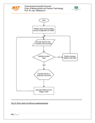
• The software code is based on the following flow chart :
➢ As stated in the tera term procedure, we have to first initialize the stepper motors using
the terminal and then proceed with the selection of motors
➢ After selecting the motor we have to select the axis, thus giving a direct control of the
position.
➢ With the selection of axis, we have to also select the parameters for movement and
direction.
➢ Next step is to validate if the selection parameters are correctly chosen or not.
➢ If yes, then calculate step for one revolution and particular movement which will in turn
give us the distance till which the shaft is going to move upwards or downwards
➢ If the input parameters are not valid, then display a message on the terminal stating
invalid input.
➢ If everything is connected properly and the parameters are chosen correctly, we will
generate PWM for the stepper motor and thus successfully position our shaft with the
rotation of the stepper motor
➢ We have implemented only for 2 axis X and Y axis . If we have a third motor , we can
have a full 3 D controlling and thus can be used for further application .
TechnischeUniversität Chemnitz
Chair of Measurement and Sensor Technology
Prof. Dr.-Ing. OlfaKanoun
20 | P a g e
Fig 12: Flow chart of software implementation
TechnischeUniversität Chemnitz
Chair of Measurement and Sensor Technology
Prof. Dr.-Ing. OlfaKanoun
21 | P a g e
5.2 Hardware Implementation
5.2.1 Connection
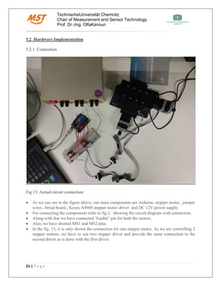
Fig 13: Actual circuit connection
• As we can see in the figure above, our main components are Arduino, stepper motor , jumper
wires , bread board , Keyes A4988 stepper motor driver and DC 12V power supply.
• For connecting the components refer to fig 2. showing the circuit diagram with connection.
• Along with that we have connected ‘Enable’ pin for both the motors.
• Also, we have shorted MS1 and MS2 pins.
• In the fig. 13, it is only shown the connection for one stepper motor. As we are controlling 2
stepper motors, we have to use two stepper driver and provide the same connection to the
second driver as is done with the first driver.
TechnischeUniversität Chemnitz
Chair of Measurement and Sensor Technology
Prof. Dr.-Ing. OlfaKanoun
22 | P a g e
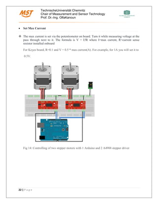
• Set Max Current
❖ The max current is set via the potentiometer on board. Turn it while measuring voltage at the
pass through next to it. The formula is V = I5R where I=max current, R=current sense
resistor installed onboard
For Keyes board, R=0.1 and V = 0.5 * max current(A). For example, for 1A you will set it to
0.5V.
Fig 14: Controlling of two stepper motors with 1 Arduino and 2 A4988 stepper driver
TechnischeUniversität Chemnitz
Chair of Measurement and Sensor Technology
Prof. Dr.-Ing. OlfaKanoun
23 | P a g e
6. Application
Stepper motor controlling helps to implement in mechanical automation for positioning and
movement of machines controlled by computers or electrical devices .
It has found its usage in several application especially 3D printer , CNC Mill conversion , Pen
Plotter . Here we have mentioned how our project can be further improvised and adapted to
develop further application :
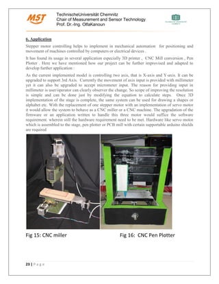
As the current implemented model is controlling two axis, that is X-axis and Y-axis. It can be
upgraded to support 3rd Axis. Currently the movement of axis input is provided with millimeter
yet it can also be upgraded to accept micrometer input. The reason for providing input in
millimeter is user/operator can clearly observer the change. So scope of improving the resolution
is simple and can be done just by modifying the equation to calculate steps. Once 3D
implementation of the stage is complete, the same system can be used for drawing a shapes or
alphabet etc. With the replacement of one stepper motor with an implementation of servo motor
it would allow the system to behave as a CNC miller or a CNC machine. The upgradation of the
firmware or an application written to handle this three motor would suffice the software
requirement. wherein still the hardware requirement need to be met. Hardware like servo motor
which is assembled to the stage, pen plotter or PCB mill with certain supportable arduino shields
are required
Fig 15: CNC miller Fig 16: CNC Pen Plotter
TechnischeUniversität Chemnitz
Chair of Measurement and Sensor Technology
Prof. Dr.-Ing. OlfaKanoun
24 | P a g e
7. Conclusion
Stepper motor advantage of Precise positioning and repeat-ability of movement have made its
presence in different automation machines. Usually good stepper motors have an accuracy of 3–
5% of a step and this error is non-cumulative from one step to the next. The controlling of
stepper motor done with Arduino as implemented in our project shows how easily the stepper
motor response to digital input and thus can be used for Robotics. Arduino as stated is an open
source platform and is easy to program and modify the code, and thus is suitable for controlling
motors . The only disadvantage of stepper motor is that they cannot run at high speed and thus
restricts it utilization in few applications.
8. Description of files
File name Description
1. Project report.docx Project description
2. Project presentation.pptx Project design and implementation
3.Arduino.ino Arduino program
4. Source files.rar Source code for project
TechnischeUniversität Chemnitz
Chair of Measurement and Sensor Technology
Prof. Dr.-Ing. OlfaKanoun
25 | P a g e
8. References
• [1]" A4988 Driver and Arduino ", Itead.cc, 2017. [Online]. Available:
https://github.com/laurb9/StepperDriver. [Accessed: 2- Jun- 2017].
• [2]" How to use A4988 to control stepper motor ", Itead.cc, 2017. [Online]. Available:
http://howtomechatronics.com/tutorials/arduino/how-to-control-stepper-motor-with-a4988-
driver-and-arduino/. [Accessed: 27- May- 2017]
• [3]" A4988 Specification and purchase ", Itead.cc, 2017. [Online]. Available:
https://www.pololu.com/product/1182 [Accessed: 21- Jun- 2017]
• [4]" Bipolar and Unipolar Stepper Motor", Itead.cc, 2017. [Online]. Available:
https://www.circuitspecialists.com/blog/unipolar-stepper-motor-vs-bipolar-stepper-motors/
[Accessed: 5- May- 2017]
• [5]" TeraTerm ", Itead.cc, 2017. [Online]. Available:
https://learn.sparkfun.com/tutorials/terminal-basics/tera-term-windows [Accessed: 20- Jun-
2017]
• [6]" Stepper motor using arduino ", Itead.cc, 2017. [Online]. Available:
http://www.instructables.com/id/Drive-a-Stepper-Motor-with-an-Arduino-and-a-A4988-/
[Accessed: 20- Apr- 2017]
• [7]" Arduino pin out ", Itead.cc, 2017. [Online]. Available:
http://www.electroschematics.com/7958/arduino-uno-pinout/ [Accessed: 13- Apr- 2017]

More Related Content

What's hot

Minor Project Report: Automatic Door Control System
Minor Project Report: Automatic Door Control SystemMinor Project Report: Automatic Door Control System
Minor Project Report: Automatic Door Control SystemSaban Kumar K.C.
 
Movement Sensed Automatic Door Opening System
Movement Sensed Automatic Door Opening SystemMovement Sensed Automatic Door Opening System
Movement Sensed Automatic Door Opening SystemEdgefxkits & Solutions
 
Obstacle Avoiding robot
Obstacle Avoiding robotObstacle Avoiding robot
Obstacle Avoiding robotDurga Singh
 
Human body temperature sensed automatic door opening system
Human body temperature sensed automatic door opening systemHuman body temperature sensed automatic door opening system
Human body temperature sensed automatic door opening systemBhumika PATEL
 
Obstacle Avoidance Robot (Powered by Arduino)
Obstacle Avoidance Robot (Powered by Arduino)Obstacle Avoidance Robot (Powered by Arduino)
Obstacle Avoidance Robot (Powered by Arduino)Amanullah Mahmood
 
Digital Tachometer using Aurdino
Digital Tachometer using AurdinoDigital Tachometer using Aurdino
Digital Tachometer using Aurdinoijtsrd
 
Obstacle_Avoidance_Robot_Coruse_Project_ECET402_Mechatronics_FinalCopy
Obstacle_Avoidance_Robot_Coruse_Project_ECET402_Mechatronics_FinalCopyObstacle_Avoidance_Robot_Coruse_Project_ECET402_Mechatronics_FinalCopy
Obstacle_Avoidance_Robot_Coruse_Project_ECET402_Mechatronics_FinalCopyElijah Barner
 
Contactless digital tachometer using microcontroller
Contactless digital tachometer using microcontroller Contactless digital tachometer using microcontroller
Contactless digital tachometer using microcontroller IJECEIAES
 
Smart door project report shivnaresh likhar
Smart door project report shivnaresh likharSmart door project report shivnaresh likhar
Smart door project report shivnaresh likharShivnaresh Likhar
 
obstacle avoiding robot
obstacle avoiding robotobstacle avoiding robot
obstacle avoiding robotssuser5ba2241
 
Arduino embedded systems and advanced robotics
Arduino embedded systems and advanced roboticsArduino embedded systems and advanced robotics
Arduino embedded systems and advanced roboticsShubham Bhattacharya
 
basic embedded system presentation
basic embedded system presentationbasic embedded system presentation
basic embedded system presentationVimal Tripathi
 
Smart door project ppt shivnaresh likhar
Smart door project ppt shivnaresh likharSmart door project ppt shivnaresh likhar
Smart door project ppt shivnaresh likharShivnaresh Likhar
 
Microprocessor project
Microprocessor projectMicroprocessor project
Microprocessor projectprapyapokharel
 
Applications of microcontroller
Applications of microcontrollerApplications of microcontroller
Applications of microcontrollerbabak danyal
 
embedded systems and robotics on avr platform
embedded systems and robotics on avr platformembedded systems and robotics on avr platform
embedded systems and robotics on avr platformNeha Sharma
 
Zigbee based metal detecting robot to assist bomb detection and rescue team
Zigbee based metal detecting robot to assist bomb detection and rescue teamZigbee based metal detecting robot to assist bomb detection and rescue team
Zigbee based metal detecting robot to assist bomb detection and rescue teamshiva kumar cheruku
 
Color Recognition with Matlab Image Processing and Matlab Interfacing with Ar...
Color Recognition with Matlab Image Processing and Matlab Interfacing with Ar...Color Recognition with Matlab Image Processing and Matlab Interfacing with Ar...
Color Recognition with Matlab Image Processing and Matlab Interfacing with Ar...Sayan Seth
 

What's hot (20)

Minor Project Report: Automatic Door Control System
Minor Project Report: Automatic Door Control SystemMinor Project Report: Automatic Door Control System
Minor Project Report: Automatic Door Control System
 
Movement Sensed Automatic Door Opening System
Movement Sensed Automatic Door Opening SystemMovement Sensed Automatic Door Opening System
Movement Sensed Automatic Door Opening System
 
Obstacle Avoiding robot
Obstacle Avoiding robotObstacle Avoiding robot
Obstacle Avoiding robot
 
Major
MajorMajor
Major
 
Human body temperature sensed automatic door opening system
Human body temperature sensed automatic door opening systemHuman body temperature sensed automatic door opening system
Human body temperature sensed automatic door opening system
 
Obstacle Avoidance Robot (Powered by Arduino)
Obstacle Avoidance Robot (Powered by Arduino)Obstacle Avoidance Robot (Powered by Arduino)
Obstacle Avoidance Robot (Powered by Arduino)
 
Digital Tachometer using Aurdino
Digital Tachometer using AurdinoDigital Tachometer using Aurdino
Digital Tachometer using Aurdino
 
Obstacle_Avoidance_Robot_Coruse_Project_ECET402_Mechatronics_FinalCopy
Obstacle_Avoidance_Robot_Coruse_Project_ECET402_Mechatronics_FinalCopyObstacle_Avoidance_Robot_Coruse_Project_ECET402_Mechatronics_FinalCopy
Obstacle_Avoidance_Robot_Coruse_Project_ECET402_Mechatronics_FinalCopy
 
Contactless digital tachometer using microcontroller
Contactless digital tachometer using microcontroller Contactless digital tachometer using microcontroller
Contactless digital tachometer using microcontroller
 
Smart door project report shivnaresh likhar
Smart door project report shivnaresh likharSmart door project report shivnaresh likhar
Smart door project report shivnaresh likhar
 
obstacle avoiding robot
obstacle avoiding robotobstacle avoiding robot
obstacle avoiding robot
 
Arduino embedded systems and advanced robotics
Arduino embedded systems and advanced roboticsArduino embedded systems and advanced robotics
Arduino embedded systems and advanced robotics
 
Obstacle avoiding robot(Lab report)
Obstacle  avoiding  robot(Lab report)Obstacle  avoiding  robot(Lab report)
Obstacle avoiding robot(Lab report)
 
basic embedded system presentation
basic embedded system presentationbasic embedded system presentation
basic embedded system presentation
 
Smart door project ppt shivnaresh likhar
Smart door project ppt shivnaresh likharSmart door project ppt shivnaresh likhar
Smart door project ppt shivnaresh likhar
 
Microprocessor project
Microprocessor projectMicroprocessor project
Microprocessor project
 
Applications of microcontroller
Applications of microcontrollerApplications of microcontroller
Applications of microcontroller
 
embedded systems and robotics on avr platform
embedded systems and robotics on avr platformembedded systems and robotics on avr platform
embedded systems and robotics on avr platform
 
Zigbee based metal detecting robot to assist bomb detection and rescue team
Zigbee based metal detecting robot to assist bomb detection and rescue teamZigbee based metal detecting robot to assist bomb detection and rescue team
Zigbee based metal detecting robot to assist bomb detection and rescue team
 
Color Recognition with Matlab Image Processing and Matlab Interfacing with Ar...
Color Recognition with Matlab Image Processing and Matlab Interfacing with Ar...Color Recognition with Matlab Image Processing and Matlab Interfacing with Ar...
Color Recognition with Matlab Image Processing and Matlab Interfacing with Ar...
 

Similar to Controlling and optimization of 3d optical stage for precise movement

RGB colour detection and tracking on MATLAB
RGB colour detection and tracking on MATLABRGB colour detection and tracking on MATLAB
RGB colour detection and tracking on MATLABNirma University
 
Three-Axis Auto Stabilizing Video Camera Platform
Three-Axis Auto Stabilizing Video Camera PlatformThree-Axis Auto Stabilizing Video Camera Platform
Three-Axis Auto Stabilizing Video Camera PlatformEklavya Sharma
 
Arduino Based Collision Prevention Warning System
Arduino Based Collision Prevention Warning SystemArduino Based Collision Prevention Warning System
Arduino Based Collision Prevention Warning SystemMadhav Reddy Chintapalli
 
Fire Fighting Robot
Fire Fighting RobotFire Fighting Robot
Fire Fighting RobotSaadullah74
 
3 Axis Drawing Machine
3 Axis Drawing Machine3 Axis Drawing Machine
3 Axis Drawing MachineIRJET Journal
 
PCB layout using CNC machine
PCB layout using CNC machinePCB layout using CNC machine
PCB layout using CNC machineVenkatkumar78
 
Mini CNC Plotter and Laser Engraver
Mini CNC Plotter and Laser EngraverMini CNC Plotter and Laser Engraver
Mini CNC Plotter and Laser Engraverijtsrd
 
CNC machine using PCB layout with wireless communication
CNC machine using PCB layout with wireless communicationCNC machine using PCB layout with wireless communication
CNC machine using PCB layout with wireless communicationVenkatkumar78
 
Microcontroller based Ultrasonic Radar (Microprocessors and Embedded Systems ...
Microcontroller based Ultrasonic Radar (Microprocessors and Embedded Systems ...Microcontroller based Ultrasonic Radar (Microprocessors and Embedded Systems ...
Microcontroller based Ultrasonic Radar (Microprocessors and Embedded Systems ...Tawsif Rahman Chowdhury
 
GSM based agriculture monitoring system
GSM based agriculture monitoring systemGSM based agriculture monitoring system
GSM based agriculture monitoring systemIRJET Journal
 
IRJET - Mobile Application Base Voice Command Wireless CNC Writing Machine
IRJET - Mobile Application Base Voice Command Wireless CNC Writing MachineIRJET - Mobile Application Base Voice Command Wireless CNC Writing Machine
IRJET - Mobile Application Base Voice Command Wireless CNC Writing MachineIRJET Journal
 
Robotics Report final.compressed (1)
Robotics Report final.compressed (1)Robotics Report final.compressed (1)
Robotics Report final.compressed (1)Kael Kristjanson
 
Ball following Robot using ESP32-cam & Arduino UNO
Ball following Robot using ESP32-cam & Arduino UNOBall following Robot using ESP32-cam & Arduino UNO
Ball following Robot using ESP32-cam & Arduino UNOIRJET Journal
 
Automatic mini CNC machine for PCB drawing and drilling
Automatic mini CNC machine for PCB drawing and drillingAutomatic mini CNC machine for PCB drawing and drilling
Automatic mini CNC machine for PCB drawing and drillingIRJET Journal
 
IRJET - Footstep Power Generation using Piezo Electric Sensor
IRJET -  	  Footstep Power Generation using Piezo Electric SensorIRJET -  	  Footstep Power Generation using Piezo Electric Sensor
IRJET - Footstep Power Generation using Piezo Electric SensorIRJET Journal
 
IRJET- Automated Elevator-An Attentive Elevator to Elevate using Speech Recog...
IRJET- Automated Elevator-An Attentive Elevator to Elevate using Speech Recog...IRJET- Automated Elevator-An Attentive Elevator to Elevate using Speech Recog...
IRJET- Automated Elevator-An Attentive Elevator to Elevate using Speech Recog...IRJET Journal
 

Similar to Controlling and optimization of 3d optical stage for precise movement (20)

Team7 report
Team7 reportTeam7 report
Team7 report
 
RGB colour detection and tracking on MATLAB
RGB colour detection and tracking on MATLABRGB colour detection and tracking on MATLAB
RGB colour detection and tracking on MATLAB
 
Three-Axis Auto Stabilizing Video Camera Platform
Three-Axis Auto Stabilizing Video Camera PlatformThree-Axis Auto Stabilizing Video Camera Platform
Three-Axis Auto Stabilizing Video Camera Platform
 
Arduino Based Collision Prevention Warning System
Arduino Based Collision Prevention Warning SystemArduino Based Collision Prevention Warning System
Arduino Based Collision Prevention Warning System
 
CNC DRAWBOT
CNC DRAWBOTCNC DRAWBOT
CNC DRAWBOT
 
Fire Fighting Robot
Fire Fighting RobotFire Fighting Robot
Fire Fighting Robot
 
3 Axis Drawing Machine
3 Axis Drawing Machine3 Axis Drawing Machine
3 Axis Drawing Machine
 
PCB layout using CNC machine
PCB layout using CNC machinePCB layout using CNC machine
PCB layout using CNC machine
 
NC-CNC-DNC |Harin Prajapari |Mechanical Engineering |GTU
NC-CNC-DNC |Harin Prajapari |Mechanical Engineering |GTU NC-CNC-DNC |Harin Prajapari |Mechanical Engineering |GTU
NC-CNC-DNC |Harin Prajapari |Mechanical Engineering |GTU
 
Mini CNC Plotter and Laser Engraver
Mini CNC Plotter and Laser EngraverMini CNC Plotter and Laser Engraver
Mini CNC Plotter and Laser Engraver
 
CNC machine using PCB layout with wireless communication
CNC machine using PCB layout with wireless communicationCNC machine using PCB layout with wireless communication
CNC machine using PCB layout with wireless communication
 
Microcontroller based Ultrasonic Radar (Microprocessors and Embedded Systems ...
Microcontroller based Ultrasonic Radar (Microprocessors and Embedded Systems ...Microcontroller based Ultrasonic Radar (Microprocessors and Embedded Systems ...
Microcontroller based Ultrasonic Radar (Microprocessors and Embedded Systems ...
 
GSM based agriculture monitoring system
GSM based agriculture monitoring systemGSM based agriculture monitoring system
GSM based agriculture monitoring system
 
IRJET - Mobile Application Base Voice Command Wireless CNC Writing Machine
IRJET - Mobile Application Base Voice Command Wireless CNC Writing MachineIRJET - Mobile Application Base Voice Command Wireless CNC Writing Machine
IRJET - Mobile Application Base Voice Command Wireless CNC Writing Machine
 
Robotics Report final.compressed (1)
Robotics Report final.compressed (1)Robotics Report final.compressed (1)
Robotics Report final.compressed (1)
 
Ball following Robot using ESP32-cam & Arduino UNO
Ball following Robot using ESP32-cam & Arduino UNOBall following Robot using ESP32-cam & Arduino UNO
Ball following Robot using ESP32-cam & Arduino UNO
 
Automatic mini CNC machine for PCB drawing and drilling
Automatic mini CNC machine for PCB drawing and drillingAutomatic mini CNC machine for PCB drawing and drilling
Automatic mini CNC machine for PCB drawing and drilling
 
IRJET - Footstep Power Generation using Piezo Electric Sensor
IRJET -  	  Footstep Power Generation using Piezo Electric SensorIRJET -  	  Footstep Power Generation using Piezo Electric Sensor
IRJET - Footstep Power Generation using Piezo Electric Sensor
 
Animatronic hand controller
Animatronic hand controllerAnimatronic hand controller
Animatronic hand controller
 
IRJET- Automated Elevator-An Attentive Elevator to Elevate using Speech Recog...
IRJET- Automated Elevator-An Attentive Elevator to Elevate using Speech Recog...IRJET- Automated Elevator-An Attentive Elevator to Elevate using Speech Recog...
IRJET- Automated Elevator-An Attentive Elevator to Elevate using Speech Recog...
 

Recently uploaded

Microscopic Analysis of Ceramic Materials.pptx
Microscopic Analysis of Ceramic Materials.pptxMicroscopic Analysis of Ceramic Materials.pptx
Microscopic Analysis of Ceramic Materials.pptxpurnimasatapathy1234
 
OSVC_Meta-Data based Simulation Automation to overcome Verification Challenge...
OSVC_Meta-Data based Simulation Automation to overcome Verification Challenge...OSVC_Meta-Data based Simulation Automation to overcome Verification Challenge...
OSVC_Meta-Data based Simulation Automation to overcome Verification Challenge...Soham Mondal
 
SPICE PARK APR2024 ( 6,793 SPICE Models )
SPICE PARK APR2024 ( 6,793 SPICE Models )SPICE PARK APR2024 ( 6,793 SPICE Models )
SPICE PARK APR2024 ( 6,793 SPICE Models )Tsuyoshi Horigome
 
IMPLICATIONS OF THE ABOVE HOLISTIC UNDERSTANDING OF HARMONY ON PROFESSIONAL E...
IMPLICATIONS OF THE ABOVE HOLISTIC UNDERSTANDING OF HARMONY ON PROFESSIONAL E...IMPLICATIONS OF THE ABOVE HOLISTIC UNDERSTANDING OF HARMONY ON PROFESSIONAL E...
IMPLICATIONS OF THE ABOVE HOLISTIC UNDERSTANDING OF HARMONY ON PROFESSIONAL E...RajaP95
 
(RIA) Call Girls Bhosari ( 7001035870 ) HI-Fi Pune Escorts Service
(RIA) Call Girls Bhosari ( 7001035870 ) HI-Fi Pune Escorts Service(RIA) Call Girls Bhosari ( 7001035870 ) HI-Fi Pune Escorts Service
(RIA) Call Girls Bhosari ( 7001035870 ) HI-Fi Pune Escorts Serviceranjana rawat
 
(ANVI) Koregaon Park Call Girls Just Call 7001035870 [ Cash on Delivery ] Pun...
(ANVI) Koregaon Park Call Girls Just Call 7001035870 [ Cash on Delivery ] Pun...(ANVI) Koregaon Park Call Girls Just Call 7001035870 [ Cash on Delivery ] Pun...
(ANVI) Koregaon Park Call Girls Just Call 7001035870 [ Cash on Delivery ] Pun...ranjana rawat
 
Top Rated Pune Call Girls Budhwar Peth ⟟ 6297143586 ⟟ Call Me For Genuine Se...
Top Rated  Pune Call Girls Budhwar Peth ⟟ 6297143586 ⟟ Call Me For Genuine Se...Top Rated  Pune Call Girls Budhwar Peth ⟟ 6297143586 ⟟ Call Me For Genuine Se...
Top Rated Pune Call Girls Budhwar Peth ⟟ 6297143586 ⟟ Call Me For Genuine Se...Call Girls in Nagpur High Profile
 
Introduction to Multiple Access Protocol.pptx
Introduction to Multiple Access Protocol.pptxIntroduction to Multiple Access Protocol.pptx
Introduction to Multiple Access Protocol.pptxupamatechverse
 
MANUFACTURING PROCESS-II UNIT-5 NC MACHINE TOOLS
MANUFACTURING PROCESS-II UNIT-5 NC MACHINE TOOLSMANUFACTURING PROCESS-II UNIT-5 NC MACHINE TOOLS
MANUFACTURING PROCESS-II UNIT-5 NC MACHINE TOOLSSIVASHANKAR N
 
Coefficient of Thermal Expansion and their Importance.pptx
Coefficient of Thermal Expansion and their Importance.pptxCoefficient of Thermal Expansion and their Importance.pptx
Coefficient of Thermal Expansion and their Importance.pptxAsutosh Ranjan
 
KubeKraft presentation @CloudNativeHooghly
KubeKraft presentation @CloudNativeHooghlyKubeKraft presentation @CloudNativeHooghly
KubeKraft presentation @CloudNativeHooghlysanyuktamishra911
 
MANUFACTURING PROCESS-II UNIT-2 LATHE MACHINE
MANUFACTURING PROCESS-II UNIT-2 LATHE MACHINEMANUFACTURING PROCESS-II UNIT-2 LATHE MACHINE
MANUFACTURING PROCESS-II UNIT-2 LATHE MACHINESIVASHANKAR N
 
Software Development Life Cycle By Team Orange (Dept. of Pharmacy)
Software Development Life Cycle By  Team Orange (Dept. of Pharmacy)Software Development Life Cycle By  Team Orange (Dept. of Pharmacy)
Software Development Life Cycle By Team Orange (Dept. of Pharmacy)Suman Mia
 
(MEERA) Dapodi Call Girls Just Call 7001035870 [ Cash on Delivery ] Pune Escorts
(MEERA) Dapodi Call Girls Just Call 7001035870 [ Cash on Delivery ] Pune Escorts(MEERA) Dapodi Call Girls Just Call 7001035870 [ Cash on Delivery ] Pune Escorts
(MEERA) Dapodi Call Girls Just Call 7001035870 [ Cash on Delivery ] Pune Escortsranjana rawat
 
Processing & Properties of Floor and Wall Tiles.pptx
Processing & Properties of Floor and Wall Tiles.pptxProcessing & Properties of Floor and Wall Tiles.pptx
Processing & Properties of Floor and Wall Tiles.pptxpranjaldaimarysona
 
Call Girls Service Nagpur Tanvi Call 7001035870 Meet With Nagpur Escorts
Call Girls Service Nagpur Tanvi Call 7001035870 Meet With Nagpur EscortsCall Girls Service Nagpur Tanvi Call 7001035870 Meet With Nagpur Escorts
Call Girls Service Nagpur Tanvi Call 7001035870 Meet With Nagpur EscortsCall Girls in Nagpur High Profile
 
UNIT-II FMM-Flow Through Circular Conduits
UNIT-II FMM-Flow Through Circular ConduitsUNIT-II FMM-Flow Through Circular Conduits
UNIT-II FMM-Flow Through Circular Conduitsrknatarajan
 
Introduction and different types of Ethernet.pptx
Introduction and different types of Ethernet.pptxIntroduction and different types of Ethernet.pptx
Introduction and different types of Ethernet.pptxupamatechverse
 
(PRIYA) Rajgurunagar Call Girls Just Call 7001035870 [ Cash on Delivery ] Pun...
(PRIYA) Rajgurunagar Call Girls Just Call 7001035870 [ Cash on Delivery ] Pun...(PRIYA) Rajgurunagar Call Girls Just Call 7001035870 [ Cash on Delivery ] Pun...
(PRIYA) Rajgurunagar Call Girls Just Call 7001035870 [ Cash on Delivery ] Pun...ranjana rawat
 
High Profile Call Girls Nagpur Meera Call 7001035870 Meet With Nagpur Escorts
High Profile Call Girls Nagpur Meera Call 7001035870 Meet With Nagpur EscortsHigh Profile Call Girls Nagpur Meera Call 7001035870 Meet With Nagpur Escorts
High Profile Call Girls Nagpur Meera Call 7001035870 Meet With Nagpur EscortsCall Girls in Nagpur High Profile
 

Recently uploaded (20)

Microscopic Analysis of Ceramic Materials.pptx
Microscopic Analysis of Ceramic Materials.pptxMicroscopic Analysis of Ceramic Materials.pptx
Microscopic Analysis of Ceramic Materials.pptx
 
OSVC_Meta-Data based Simulation Automation to overcome Verification Challenge...
OSVC_Meta-Data based Simulation Automation to overcome Verification Challenge...OSVC_Meta-Data based Simulation Automation to overcome Verification Challenge...
OSVC_Meta-Data based Simulation Automation to overcome Verification Challenge...
 
SPICE PARK APR2024 ( 6,793 SPICE Models )
SPICE PARK APR2024 ( 6,793 SPICE Models )SPICE PARK APR2024 ( 6,793 SPICE Models )
SPICE PARK APR2024 ( 6,793 SPICE Models )
 
IMPLICATIONS OF THE ABOVE HOLISTIC UNDERSTANDING OF HARMONY ON PROFESSIONAL E...
IMPLICATIONS OF THE ABOVE HOLISTIC UNDERSTANDING OF HARMONY ON PROFESSIONAL E...IMPLICATIONS OF THE ABOVE HOLISTIC UNDERSTANDING OF HARMONY ON PROFESSIONAL E...
IMPLICATIONS OF THE ABOVE HOLISTIC UNDERSTANDING OF HARMONY ON PROFESSIONAL E...
 
(RIA) Call Girls Bhosari ( 7001035870 ) HI-Fi Pune Escorts Service
(RIA) Call Girls Bhosari ( 7001035870 ) HI-Fi Pune Escorts Service(RIA) Call Girls Bhosari ( 7001035870 ) HI-Fi Pune Escorts Service
(RIA) Call Girls Bhosari ( 7001035870 ) HI-Fi Pune Escorts Service
 
(ANVI) Koregaon Park Call Girls Just Call 7001035870 [ Cash on Delivery ] Pun...
(ANVI) Koregaon Park Call Girls Just Call 7001035870 [ Cash on Delivery ] Pun...(ANVI) Koregaon Park Call Girls Just Call 7001035870 [ Cash on Delivery ] Pun...
(ANVI) Koregaon Park Call Girls Just Call 7001035870 [ Cash on Delivery ] Pun...
 
Top Rated Pune Call Girls Budhwar Peth ⟟ 6297143586 ⟟ Call Me For Genuine Se...
Top Rated  Pune Call Girls Budhwar Peth ⟟ 6297143586 ⟟ Call Me For Genuine Se...Top Rated  Pune Call Girls Budhwar Peth ⟟ 6297143586 ⟟ Call Me For Genuine Se...
Top Rated Pune Call Girls Budhwar Peth ⟟ 6297143586 ⟟ Call Me For Genuine Se...
 
Introduction to Multiple Access Protocol.pptx
Introduction to Multiple Access Protocol.pptxIntroduction to Multiple Access Protocol.pptx
Introduction to Multiple Access Protocol.pptx
 
MANUFACTURING PROCESS-II UNIT-5 NC MACHINE TOOLS
MANUFACTURING PROCESS-II UNIT-5 NC MACHINE TOOLSMANUFACTURING PROCESS-II UNIT-5 NC MACHINE TOOLS
MANUFACTURING PROCESS-II UNIT-5 NC MACHINE TOOLS
 
Coefficient of Thermal Expansion and their Importance.pptx
Coefficient of Thermal Expansion and their Importance.pptxCoefficient of Thermal Expansion and their Importance.pptx
Coefficient of Thermal Expansion and their Importance.pptx
 
KubeKraft presentation @CloudNativeHooghly
KubeKraft presentation @CloudNativeHooghlyKubeKraft presentation @CloudNativeHooghly
KubeKraft presentation @CloudNativeHooghly
 
MANUFACTURING PROCESS-II UNIT-2 LATHE MACHINE
MANUFACTURING PROCESS-II UNIT-2 LATHE MACHINEMANUFACTURING PROCESS-II UNIT-2 LATHE MACHINE
MANUFACTURING PROCESS-II UNIT-2 LATHE MACHINE
 
Software Development Life Cycle By Team Orange (Dept. of Pharmacy)
Software Development Life Cycle By  Team Orange (Dept. of Pharmacy)Software Development Life Cycle By  Team Orange (Dept. of Pharmacy)
Software Development Life Cycle By Team Orange (Dept. of Pharmacy)
 
(MEERA) Dapodi Call Girls Just Call 7001035870 [ Cash on Delivery ] Pune Escorts
(MEERA) Dapodi Call Girls Just Call 7001035870 [ Cash on Delivery ] Pune Escorts(MEERA) Dapodi Call Girls Just Call 7001035870 [ Cash on Delivery ] Pune Escorts
(MEERA) Dapodi Call Girls Just Call 7001035870 [ Cash on Delivery ] Pune Escorts
 
Processing & Properties of Floor and Wall Tiles.pptx
Processing & Properties of Floor and Wall Tiles.pptxProcessing & Properties of Floor and Wall Tiles.pptx
Processing & Properties of Floor and Wall Tiles.pptx
 
Call Girls Service Nagpur Tanvi Call 7001035870 Meet With Nagpur Escorts
Call Girls Service Nagpur Tanvi Call 7001035870 Meet With Nagpur EscortsCall Girls Service Nagpur Tanvi Call 7001035870 Meet With Nagpur Escorts
Call Girls Service Nagpur Tanvi Call 7001035870 Meet With Nagpur Escorts
 
UNIT-II FMM-Flow Through Circular Conduits
UNIT-II FMM-Flow Through Circular ConduitsUNIT-II FMM-Flow Through Circular Conduits
UNIT-II FMM-Flow Through Circular Conduits
 
Introduction and different types of Ethernet.pptx
Introduction and different types of Ethernet.pptxIntroduction and different types of Ethernet.pptx
Introduction and different types of Ethernet.pptx
 
(PRIYA) Rajgurunagar Call Girls Just Call 7001035870 [ Cash on Delivery ] Pun...
(PRIYA) Rajgurunagar Call Girls Just Call 7001035870 [ Cash on Delivery ] Pun...(PRIYA) Rajgurunagar Call Girls Just Call 7001035870 [ Cash on Delivery ] Pun...
(PRIYA) Rajgurunagar Call Girls Just Call 7001035870 [ Cash on Delivery ] Pun...
 
High Profile Call Girls Nagpur Meera Call 7001035870 Meet With Nagpur Escorts
High Profile Call Girls Nagpur Meera Call 7001035870 Meet With Nagpur EscortsHigh Profile Call Girls Nagpur Meera Call 7001035870 Meet With Nagpur Escorts
High Profile Call Girls Nagpur Meera Call 7001035870 Meet With Nagpur Escorts
 

Controlling and optimization of 3d optical stage for precise movement

  • 1. TechnischeUniversität Chemnitz Chair of Measurement and Sensor Technology Prof. Dr.-Ing. OlfaKanoun 1 | P a g e Department of Electrical Engineering and Information Technology Chair of Measurement and Sensor Technology “Controlling and optimization of 3D optical stage for precise movement” Project Lab Embedded Systems Group: 13 Members: AvadhutKhade Vinay Venu Yash Inaniya Supervisor: Ammar Al-Hamry Date: 24/6/2017
  • 2. TechnischeUniversität Chemnitz Chair of Measurement and Sensor Technology Prof. Dr.-Ing. OlfaKanoun 2 | P a g e Contents Abstract ……………………………………………………………………………………… 3 List of figures………………………………………………………………………………… 4 List of tables ………………………………………………………………………………………………………………………………….. 5 1. Introduction……………………………………………………………………………… 6 2. Members Responsibility………………………………………………………………… 6 3. Project Description……………………………………………………………………… 7 3.1 Definition……………………………………………………………………….. 7 3.2 Details…………………………………………………………………………… 7 3.3 Block Diagram………………………………………………………………….. 7 3.4 Circuit Diagram…………………………………………………………………. 8 4. Components Required…………………………………………………………………... 9 4.1 Specification and Requirement…………………………………………………. 9 4.1.1 Arduino Uno………………………………………………………………… 9 4.1.2 Keyes A4988 stepper motor driver…………………………………………..11 4.1.3 Stepper motor ………………………………………………………………..13 5. Project Implementation…………………………………………………………………..15 5.1 Software …………………………………………………………………………15 5.1.1 Arduino Uno (Code Generation)……………………………………………. 15 5.1.2 Tera Term (Serial Communication )…………………………………………17 5.1.3 Flow chart…………………………………………………………………… 19 5.2 Hardware…………………………………………………………………………21 5.2.1 Actual connection Diagram…………………………………………………..21 5.2.2 Set Max Current……...………………………………………………………22 6. Applications………………………………………………………………………………23 7. Conclusion………………………………………………………………………………..24 8. Description of files………………………………………………………………………..24 9. References………………………………………………………………………………...25
  • 3. TechnischeUniversität Chemnitz Chair of Measurement and Sensor Technology Prof. Dr.-Ing. OlfaKanoun 3 | P a g e List of figures 1. Block diagram of design implementation 2. Arduino and A4988 driver connections to stepper motor 3. Arduino board layout 4. A4988 Keyes Stepper Motor Driver 5. Schematic diagram of the A4988 stepper motor driver carrier 6. Cross-sectional view of Stepper Motor 7. Bipolar Stepper motor 8. Project stepper motor interfaced using RS232 serial communication 9. Arduino IDE 10. Tera Term setting to select serial communication 11. Motor selection from terminal 12. Flow chart of software implementation 13. Actual circuit connection 14. Controlling of two stepper motors with 1 Arduino and 2 A4988 stepper driver 15. CNC miller 16. CNC Pen Plotter
  • 4. TechnischeUniversität Chemnitz Chair of Measurement and Sensor Technology Prof. Dr.-Ing. OlfaKanoun 4 | P a g e List of Tables 1. Pin description of Arduino Uno 2. Operating voltage range of A4988
  • 5. TechnischeUniversität Chemnitz Chair of Measurement and Sensor Technology Prof. Dr.-Ing. OlfaKanoun 5 | P a g e Abstract Stepper motor has been quite popular in Industrial Automation and Robotics. It’s simple working principle and operation has made its usage inevitable in areas relating to control and positioning. Computer controlled stepper motor are in high demand as they provide precise positioning and thus lay down the ground for our project where we implement control of stepper motor using Arduino Uno.
  • 6. TechnischeUniversität Chemnitz Chair of Measurement and Sensor Technology Prof. Dr.-Ing. OlfaKanoun 6 | P a g e 1.Introduction In today’s Industrial automation and robotics, whenever we want to control the position of an instrument according to our requirements, stepper motor is the easiest solution available. Stepper motor, a DC electric motor rotates in the form of number of equal steps. The motor position can be controlled and be hold at particular step which helps us to get the precise position we want to achieve. Due to its advantage of precise positioning, speed control and low speed torque, stepper motor has found its usage in several application like 3D Printer, Camera Platforms and X, Y plotters. With the advent of Arduino microcontroller boards, it is easy to control the stepper motor in desired steps. Stepper motor has been quite popular in robotics due to their ability to move in steps .The advantage of these motors is that they can be made to response using digital input which in turn makes it easy to control and less costly. 2. Members Responsibilities Members Responsibilities Avadhut Khade • Circuit designing • Hardware components research • RS232 configuration • Presentation Vinay Venu • Software Implementation • Source code development • Stepper motor Analysis • Presentation Yash Inaniya • Circuit Designing • Debugging/Source code optimization • Signal tapping • Report
  • 7. TechnischeUniversität Chemnitz Chair of Measurement and Sensor Technology Prof. Dr.-Ing. OlfaKanoun 7 | P a g e 3. Project Description 3.1 Definition Controlling of two stepper motors mounted on the microscope instrument for x-y direction using an Arduino Uno board and stepper motor driver. Precise positioning of Laser through the microscope to focus on the miniature sensor. 3.2 Details As the project requires precise focus of the laser beam, it can be realized by controlling of the stepper motor mounted on the microscope instrument through which the laser is passing. The simplest way to do that is with Arduino Uno. Arduino Uno has inbuilt library for stepper motor and thus can be easily applied for controlling stepper motor. The output of stepper motor is a RS232 serial communication cable which is interfaced with the Keyes A4988 stepper driver board. The stepper driver board is the central communication device here and will vary the voltage to keep a constant current across the stepper motor. The driver also provides the required step resolutions in five different types and thus can be suited for different positioning. The software part is implemented through Arduino which also sends signal to the driver as to how many steps the motor should run. The value of the number of steps is input through the terminal and accordingly the motor is selected for either X positioning or Y positioning. 3.3 Block Diagram Fig 1: Block diagram of design implementation Keyes A4988 Stepper Motor Driver Bipolar Stepper Motor Arduino Uno Board Power supply Computer or laptopStepper Motor
  • 8. TechnischeUniversität Chemnitz Chair of Measurement and Sensor Technology Prof. Dr.-Ing. OlfaKanoun 8 | P a g e 3.4 Circuit Diagram Fig 2: Arduino and A4988 driver connections to stepper motor The connection of the circuit on the bread board is easy and straight forward. As the stepper motor here is bipolar, therefore the 2 coils are connected to the A4988 Keyes stepper board as marked in the figure to the pins 2B , 2A , 1A, 1B . Other connection are listed below : Arduino Uno to Keyes board : • DIR – D8 • STEP – D9 • GND - Arduino GND • GND - Motor power GND • VMOT - Motor power • A4988/DRV8825 microstep control o MS1/MODE0 - D10 ▪ MS2/MODE1 - D11 ▪ MS3/MODE2 - D12 • DRV8834 microstep control ▪ M0 - D10 ▪ M1 - D11 • ENABLE - D13(To check if coils are active) A 100 µf capacitor is connected ground and voltage for motor (Vmot) to protect the driver from voltage spikes.
  • 9. TechnischeUniversität Chemnitz Chair of Measurement and Sensor Technology Prof. Dr.-Ing. OlfaKanoun 9 | P a g e 4. Components Required • Arduino Uno board • 2 Bipolar Stepper motor • Keyes A4988 Stepper Motor Driver • 100 µf Capacitor • 12 DC Power supply • Connecting / Hook-up / Jump wires • A breadboard 4.1 Component specification The technical specification of the components used is specified here : 4.1.1 Arduino Uno Arduino is an open-source prototyping platform based on an easy-to-use hardware and software.Arduino UNO (Fig 3) is a microcontroller board based on ATMega328P. It has 14 digital input/output pins (6 can be used as PWM outputs) and 6 analog inputs (description in Table). The 16 MHz quartz crystal controls the timing and clock of the UNO board. The communications to the UNO board is through the USB cable which powers the board as well. A separate power jack is provided for remote applications. The operating voltage of the UNO board is 5V. It has 2 KB SRAM and 32 KB Flash memory. The board can be programmed using Arduino IDE software and the hex code can directly be flashed to the board without any external programming devices Fig 3: Arduino Uno Board
  • 10. TechnischeUniversität Chemnitz Chair of Measurement and Sensor Technology Prof. Dr.-Ing. OlfaKanoun 10 | P a g e Details of Arduino Pins S No Name of the Pin Function of Pin 1. USB Plug Serial communication interface between Arduino and PC 2. Analog reference pin (AREF) Analog reference pin that decides the reference voltage for ADC 3. Digital ground Ground for digital inputs. 4. Digital I/O Pins (2-13) Pins to read and write digital data. Total of 12 pins, where 6 pins support PWM 5. Serial Out Serial Communication Output Port 6. Serial In (Rx) Serial Communication Input Port 7. Reset Button Hardware Reset. The button with the highest priority. 8. In-Circuit Serial Programmer (ICSP) The ICSP pin has two purposes: (a) Boot-loading (b) SPI communication Boot-loader is a program which runs prior to the start of Arduino IDE. SPI is a serial synchronous data protocol used by the Atmega328 microcontroller to communicate with peripheral devices 9. Atmega328 microcontroller Processor manufactured by Atmel, the main processor of the Arduino UNO board 10. Analog pins (0-5) Analog input pins. These support digital input/output as well. 11. Voltage in (Vin) Input voltage 12. Ground pins Voltage reference ground 13. 5V power pin 5V power pin is used for giving 5V to Arduino Uno Board
  • 11. TechnischeUniversität Chemnitz Chair of Measurement and Sensor Technology Prof. Dr.-Ing. OlfaKanoun 11 | P a g e Table 1 : Pin description of Arduino Uno 4.1.2 Keyes A4988 stepper motor driver ❖ The A4988 is a microstepping driver for controlling bipolar stepper motors which has built- in translator for easy operation. This means that we can control the stepper motor with just 2 pins from our controller, or one for controlling the rotation direction and the other for controlling the steps. ❖ The Driver provides five different step resolutions: full-step, haft-step, quarter-step, eight- step and sixteenth-step. Also, it has a potentiometer for adjusting the current output, over- temperature thermal shutdown and crossover-current protection. Fig 4: A4988 Keyes Stepper Motor Driver ❖ Its logic voltage is from 3 to 5.5 V and the maximum current per phase is 2A if good addition cooling is provided or 1A continuous current per phase without heat sink or cooling ❖ The resolution (step size) selector inputs (MS1, MS2, and MS3) enable selection from the five step resolutions according to the table below. MS1 and MS3 have internal 100kΩ pull- down resistors and MS2 has an internal 50kΩ pull-down resistor, so leaving these three microstep selection pins disconnected results in full-step mode. For the microstep modes to function correctly, the current limit must be set low enough (see below) so that current 14. 3.3V power pin 3.3V inputs to Arduino Uno. Some peripherals require to be operated below 3.6V. Also used to power external shields. 15. Reset pin The function of reset pin is same as the Reset button. It is an alternative way to reset Arduino Uno. 16. External power supply pin 9V-12V external DC supply
  • 12. TechnischeUniversität Chemnitz Chair of Measurement and Sensor Technology Prof. Dr.-Ing. OlfaKanoun 12 | P a g e limiting gets engaged. Otherwise, the intermediate current levels will not be correctly maintained, and the motor will skip microsteps Table 2: Operating voltage range of A4988 ❖ One stepper driver can help us control only one stepper motor at up to 2A output current at the coil. The supply provided to the driver should have appropriate decoupling capacitors close to the board and they must deliver expected current. ❖ The A4988 driver IC has a maximum current rating of 2 A per coil, but the actual current you can deliver depends on how well you can keep the IC cool. The carrier’s printed circuit board is designed to draw heat out of the IC, but to supply more than approximately 1 A per coil, a heat sink or other cooling method is required. ❖ Each pulse to the STEP input corresponds to one microstep of the stepper motor in the direction selected by the DIR pin. The important aspect here to consider is that the STEP and DIR pins are not pulled to any voltage internally, so we should not leave either of these pins floating in our application. For rotation injust a single direction, we can tie DIR directly to VCC or GND. The chip has three different inputs for controlling its many power states: RST, SLP, and EN. ❖ For details about these power states, it is recommended to refer the datasheet. Also, the RST pin is floating ; if we are not using the pin, we can connect it to the adjacent SLP pin on the PCB to bring it high and enable the board.
  • 13. TechnischeUniversität Chemnitz Chair of Measurement and Sensor Technology Prof. Dr.-Ing. OlfaKanoun 13 | P a g e Schematic diagram Fig 5: Schematic diagram of the A4988 stepper motor driver carrier 4.1.3Stepper motor ❖ A stepper motor is an electromechanical device it converts electrical power into mechanical power. Also, it is a brushless, synchronous electric motor that can divide a full rotation into an expansive number of steps. The motor’s position can be controlled accurately without any feedback mechanism, as long as the motor is carefully sized to the application. Stepper motors are similar to switched reluctance motors. ❖ The stepper motor uses the theory of operation for magnets to make the motor shaft turn a precise distance when a pulse of electricity is provided. The stator has eight poles, and the rotor has six poles. The rotor will require 24 pulses of electricity to move the 24 steps to make one complete revolution. Another way to say this is that the rotor will move precisely 15° for each pulse of electricity that the motor receives.
  • 14. TechnischeUniversität Chemnitz Chair of Measurement and Sensor Technology Prof. Dr.-Ing. OlfaKanoun 14 | P a g e Fig 6: Cross-sectional view of Stepper Motor ➢ There are two types of stepper motors : ▪ Unipolar &Bipolar Stepper motors In our project, we are using Bipolar stepper motors and with bipolar stepper motors there is only a single winding per phase. The driving circuit needs to be more complicated to reverse the magnetic pole, this is done to reverse the current in the winding. This is done with a H-bridge arrangement, however there are several driver chips that can be purchased to make this a simpler task.Unlike the unipolar stepper motor, the bipolar stepper motor has two leads per phase, neither of which are common. Static friction effects do happen with a H-bridge with certain drive topologies, however this can be reduced with dithering the stepper motor signal at a higher frequency. Fig 7: Bipolar Stepper motor
  • 15. TechnischeUniversität Chemnitz Chair of Measurement and Sensor Technology Prof. Dr.-Ing. OlfaKanoun 15 | P a g e Fig 8: Project stepper motor interfaced using RS232 serial communication 5. Project implementation 5.1 Software Implementation 5.1.1 ArduinoUno ❖ The software part is implemented through Arduino Uno. To run Arduino , we can either use online Arduino IDE and save our project on cloud storage or we can download the free Arduino compiler . ❖ On the Arduino board, we are just interested in some of the pins as we are giving a digital input and therefore we don’t need to work with the analog pins ❖ The pins on the Arduino can be configured as either inputs or output ❖ Arduino (Atmega) pins default to inputs, so they don't need to be explicitly declared as inputs with pinMode() when you're using them as inputs ❖ The Arduino file contains two partwhere we have to write our code: ➢ Setup() function - The setup() function is called when a sketch starts. Use it to initialize variables, pin modes, start using libraries, etc. The setup function will only run once, after each powerup or reset of the Arduino board. ➢ Loop() function - After creating a setup() function, which initializes and sets the initial values, the loop() function does precisely what its name suggests, and loops consecutively, allowing your program to change and respond. Use it to actively control the Arduino board.
  • 16. TechnischeUniversität Chemnitz Chair of Measurement and Sensor Technology Prof. Dr.-Ing. OlfaKanoun 16 | P a g e Fig 9: Arduino IDE ❖ First we have to define the Step and Direction pins. In our case they are the pins number 4 and 2 for the first stepper motor and 10 and 8 for the second motor on the Arduino Board and they are named stepPin and dirPin and the setup section we have to define them as an outputs. • Some of the basic instruction to be used for setup are : ➢ pinMode() - Configures the specified pin to behave either as an input or an output . Syntax is pinMode(pin, mode) ➢ Begin () -Sets the data rate in bits per second (baud) for serial data transmission. For communicating with the computer, use one of these rates: 300, 600, 1200, 2400, 4800, 9600, 14400, 19200, 28800, 38400, 57600, or 115200. You can, however, specify other rates - for example, to communicate over pins 0 and 1 with a component that requires a particular baud rate.Syntax -Serial.begin(speed) ➢ Serial.setTimeout() - It sets the maximum milliseconds to wait for serial data when using Serial.readBytesUntil(), Serial.readBytes(), Serial.parseInt() or Serial.parseFloat(). It defaults to 1000 milliseconds ➢ Also, we have used Enable signal here for both the stepper motors , so it is initialized at the beginning of the code and in the setup is connected to pin 6 and 12 respectively .
  • 17. TechnischeUniversität Chemnitz Chair of Measurement and Sensor Technology Prof. Dr.-Ing. OlfaKanoun 17 | P a g e ❖ Basic Instruction used for main body loop are : ➢ Println() - Prints data to the serial port as human-readable ASCII text. This command can take many forms. Numbers are printed using an ASCII character for each digit. Floats are similarly printed as ASCII digits, defaulting to two decimal places. Bytes are sent as a single character. Characters and strings are sent as is .Syntax -Serial.printin(val) ➢ digitalWrite()- Write a HIGH or a LOW value to a digital pin.If the pin has been configured as an OUTPUT with pinMode(), its voltage will be set to the corresponding value: 5V (or 3.3V on 3.3V boards) for HIGH, 0V (ground) for LOW.If the pin is configured as an INPUT, digitalWrite() will enable (HIGH) or disable (LOW) the internal pullup on the input pin. It is recommended to set the pinMode() to INPUT_PULLUP to enable the internal pull-up resistor. ➢ digitalRead() - Reads the value from a specified digital pin, either HIGH or LOW . ❖ In the loop section first we will set the Direction pin on high state that will enable the motor to move in a particular direction. Now using this for loop we will make the motor make one full cycle rotation. As the driver is set on Full Step Mode and our Stepper Motor has 1.8 degrees step angle, or 200 steps, we need to send 200 pulses into the Step Pin to make one full cycle rotation. So the for loop will have 200 iterations and each time it will set the Step pin on high and then low state for making the pulses. Between each digitalWrite we need add some delay from which the speed of the motor will depend. ❖ After this full cycle rotation we will make one second delay, then change the direction of rotation by setting the dirPin on a low state and now make 2 full cycle rotations with this loop of 400 iterations. At the end there is one more second delay. Now let’s upload the code and see how it will work. ❖ For serial communication , there are different software available and in our project we have used “Tera Term” software as terminal to give input value to the stepper motor . 5.1.2 Tera Term Software • Tera Term (rarely TeraTerm) is an open-source, free, software implemented, terminal emulator (communications) program. It emulates different types of computer terminals, from DEC VT100 to DEC VT382 • We should see a “TeraTerm: New connection” pop-up within the program as soon as you open Tera Term icon after installing it. Here, you can select which serial port we’d like to open up. Select the “Serial ” radio button. Then select your port from the drop-down menu.If the Ardunio Uno is already connected to the computer , it will show in the list. (If this window doesn’t open when you start TeraTerm, you can get here by going to **File > New connection…“.)
  • 18. TechnischeUniversität Chemnitz Chair of Measurement and Sensor Technology Prof. Dr.-Ing. OlfaKanoun 18 | P a g e Fig 10: Tera Term setting to select serial communication • Since we are controlling 2 stepper motors with one Arduino, we can use one for X-axis and the second motor for Y-axis . As soon as we select the Arduino Uno in port list , the terminal will start and it will give us the option of selection of motor ,i.e. which motor you want to select first . • After selecting the motor , we can select in which direction we want it to rotate . For that we have two options :- Clockwise and Anti-Clockwise . Select the appropriate one . Fig 11: Motor selection from terminal • The terminal is our communication with the motors . The interfacing of the terminal with the motors is already done in the arduinocode .
  • 19. TechnischeUniversität Chemnitz Chair of Measurement and Sensor Technology Prof. Dr.-Ing. OlfaKanoun 19 | P a g e • The stepper motor is connected directly to a shaft and with rotation in the motor makes the shaft position goes up and down. Select the appropriate distance you want the shaft to move in millimeters. • If you want to get really fast with TeraTerm, some of these shortcuts really help : • ALT+N: Connects to a new serial port. • ALT+I: Disconnects from the current port. • ALT+V: Pastes text from clipboard to the serial port (not CTRL+V). • ALT+C: Copy selected text into clipboard (not CTRL+C). • CTRL+TAB: Switch between two TeraTerm windows 5.1.3 Flow Chart • The software code is based on the following flow chart : ➢ As stated in the tera term procedure, we have to first initialize the stepper motors using the terminal and then proceed with the selection of motors ➢ After selecting the motor we have to select the axis, thus giving a direct control of the position. ➢ With the selection of axis, we have to also select the parameters for movement and direction. ➢ Next step is to validate if the selection parameters are correctly chosen or not. ➢ If yes, then calculate step for one revolution and particular movement which will in turn give us the distance till which the shaft is going to move upwards or downwards ➢ If the input parameters are not valid, then display a message on the terminal stating invalid input. ➢ If everything is connected properly and the parameters are chosen correctly, we will generate PWM for the stepper motor and thus successfully position our shaft with the rotation of the stepper motor ➢ We have implemented only for 2 axis X and Y axis . If we have a third motor , we can have a full 3 D controlling and thus can be used for further application .
  • 20. TechnischeUniversität Chemnitz Chair of Measurement and Sensor Technology Prof. Dr.-Ing. OlfaKanoun 20 | P a g e Fig 12: Flow chart of software implementation
  • 21. TechnischeUniversität Chemnitz Chair of Measurement and Sensor Technology Prof. Dr.-Ing. OlfaKanoun 21 | P a g e 5.2 Hardware Implementation 5.2.1 Connection Fig 13: Actual circuit connection • As we can see in the figure above, our main components are Arduino, stepper motor , jumper wires , bread board , Keyes A4988 stepper motor driver and DC 12V power supply. • For connecting the components refer to fig 2. showing the circuit diagram with connection. • Along with that we have connected ‘Enable’ pin for both the motors. • Also, we have shorted MS1 and MS2 pins. • In the fig. 13, it is only shown the connection for one stepper motor. As we are controlling 2 stepper motors, we have to use two stepper driver and provide the same connection to the second driver as is done with the first driver.
  • 22. TechnischeUniversität Chemnitz Chair of Measurement and Sensor Technology Prof. Dr.-Ing. OlfaKanoun 22 | P a g e • Set Max Current ❖ The max current is set via the potentiometer on board. Turn it while measuring voltage at the pass through next to it. The formula is V = I5R where I=max current, R=current sense resistor installed onboard For Keyes board, R=0.1 and V = 0.5 * max current(A). For example, for 1A you will set it to 0.5V. Fig 14: Controlling of two stepper motors with 1 Arduino and 2 A4988 stepper driver
  • 23. TechnischeUniversität Chemnitz Chair of Measurement and Sensor Technology Prof. Dr.-Ing. OlfaKanoun 23 | P a g e 6. Application Stepper motor controlling helps to implement in mechanical automation for positioning and movement of machines controlled by computers or electrical devices . It has found its usage in several application especially 3D printer , CNC Mill conversion , Pen Plotter . Here we have mentioned how our project can be further improvised and adapted to develop further application : As the current implemented model is controlling two axis, that is X-axis and Y-axis. It can be upgraded to support 3rd Axis. Currently the movement of axis input is provided with millimeter yet it can also be upgraded to accept micrometer input. The reason for providing input in millimeter is user/operator can clearly observer the change. So scope of improving the resolution is simple and can be done just by modifying the equation to calculate steps. Once 3D implementation of the stage is complete, the same system can be used for drawing a shapes or alphabet etc. With the replacement of one stepper motor with an implementation of servo motor it would allow the system to behave as a CNC miller or a CNC machine. The upgradation of the firmware or an application written to handle this three motor would suffice the software requirement. wherein still the hardware requirement need to be met. Hardware like servo motor which is assembled to the stage, pen plotter or PCB mill with certain supportable arduino shields are required Fig 15: CNC miller Fig 16: CNC Pen Plotter
  • 24. TechnischeUniversität Chemnitz Chair of Measurement and Sensor Technology Prof. Dr.-Ing. OlfaKanoun 24 | P a g e 7. Conclusion Stepper motor advantage of Precise positioning and repeat-ability of movement have made its presence in different automation machines. Usually good stepper motors have an accuracy of 3– 5% of a step and this error is non-cumulative from one step to the next. The controlling of stepper motor done with Arduino as implemented in our project shows how easily the stepper motor response to digital input and thus can be used for Robotics. Arduino as stated is an open source platform and is easy to program and modify the code, and thus is suitable for controlling motors . The only disadvantage of stepper motor is that they cannot run at high speed and thus restricts it utilization in few applications. 8. Description of files File name Description 1. Project report.docx Project description 2. Project presentation.pptx Project design and implementation 3.Arduino.ino Arduino program 4. Source files.rar Source code for project
  • 25. TechnischeUniversität Chemnitz Chair of Measurement and Sensor Technology Prof. Dr.-Ing. OlfaKanoun 25 | P a g e 8. References • [1]" A4988 Driver and Arduino ", Itead.cc, 2017. [Online]. Available: https://github.com/laurb9/StepperDriver. [Accessed: 2- Jun- 2017]. • [2]" How to use A4988 to control stepper motor ", Itead.cc, 2017. [Online]. Available: http://howtomechatronics.com/tutorials/arduino/how-to-control-stepper-motor-with-a4988- driver-and-arduino/. [Accessed: 27- May- 2017] • [3]" A4988 Specification and purchase ", Itead.cc, 2017. [Online]. Available: https://www.pololu.com/product/1182 [Accessed: 21- Jun- 2017] • [4]" Bipolar and Unipolar Stepper Motor", Itead.cc, 2017. [Online]. Available: https://www.circuitspecialists.com/blog/unipolar-stepper-motor-vs-bipolar-stepper-motors/ [Accessed: 5- May- 2017] • [5]" TeraTerm ", Itead.cc, 2017. [Online]. Available: https://learn.sparkfun.com/tutorials/terminal-basics/tera-term-windows [Accessed: 20- Jun- 2017] • [6]" Stepper motor using arduino ", Itead.cc, 2017. [Online]. Available: http://www.instructables.com/id/Drive-a-Stepper-Motor-with-an-Arduino-and-a-A4988-/ [Accessed: 20- Apr- 2017] • [7]" Arduino pin out ", Itead.cc, 2017. [Online]. Available: http://www.electroschematics.com/7958/arduino-uno-pinout/ [Accessed: 13- Apr- 2017]