Downloaded 123 times


![15
Durgapur Barrage
Details of Canal Network.
Length
(Km)
Discharge at Head
Regulator (Cumec)
LBMC (Left Bank Main Canal)(Canal
originating from Durgapur Barrage)
136.8 260
RBMC (Right Bank Main Canal) (Canal
originating from Durgapur Barrage)
88.5 64.3
Total length of main and branch canals 2494
DURGAPUR BARRAGE
Year of construction 1955
Length 692 m
Number of gates 34 (including under sluice)
Size of gates 18.3m x 4.9m [60 ft x 16 ft]
Left & right under sluice 18.3m x 5.5 m [60 ft x 18 ft]
Operating levels
Between RL. 64.5 m [211.5 ft] to RL. 63.4
m [208.0 ft]](https://image.slidesharecdn.com/maithonreport-150805132527-lva1-app6891/85/MHPS-DVC-PROJECT-REPORT-15-320.jpg)


![24
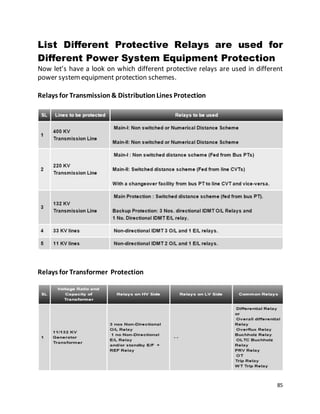
DEMAND FORECASTING & SHEDULING
08-JUL-2015
SUMMARY DAIGRAM-DVC 08-JUL-2015 11:50:52
FREQUENCY 50.05 UI RATE(PAISE) 261.36
DEV(MW) 33 TOTAL SCHEDULED 571
MAX. ADDITIONAL RATE/PENALTY RATE(OVER INJECTION)-0
BSEB JSEB DVC GRIDCO WBSEB SIKKIM
GENERATION 1 0 2711 1857 3311
DRWL SCHD -2050 -482 571 -848 -2081
ACT. DRAWL -2385 -87 604 6397 -2068
DEMAND 2385 87 2107 -4540 5379
ACTUAL GEN. SHARE OF DVC
RANGIT 61 6
CHUKHA 251 26
TEESTA 515 44
TALA 1079 60
KURICHU 38 19
FARAKKA 326 25
TALCHER 470 1
ACTUAL CONTROL ERROR = 36 K▲F= -2.63
VOL.BTW 12%-15% = 0.00
VOL.BTW 15%-20% = 0.00
VOL. BEYOND 20 % = 0.00
DVC GENERATION MW
THERMAL GEN 2635
HYDRO GEN 76
TOTAL GEN 2711TOTAL CS GEN :- 6220
NET EXPORT =1199
EXPORT RATE (PAISE/kwh)=101
CONSR CD(MVA) ACT(MW
NET IMPORT = -103
IMPORT RATE (PAISE/kwh)= 218
BSL
TISCO
DSP
IISCO
200
120
190
100
126
-30
WL 27
55
NET UI (mwh) = 1096
[ COMULATIVE SINCE 00:00 HRS]](https://image.slidesharecdn.com/maithonreport-150805132527-lva1-app6891/85/MHPS-DVC-PROJECT-REPORT-24-320.jpg)


The document provides information about the training undergone by the authors at the Maithon Hydel Power Station located in West Bengal, India. It begins with acknowledging the authorities of Maithon Hydel Power Station and Bankura Unnayani Institute of Engineering for providing the opportunity. The content section then outlines the various training reports covering topics like the Public Relations Office, Central Load Dispatch, Transmission Department, Transmission System Construction, and Central Testing Center. Tables are also included that list details of DVC power stations, dams and barrages.