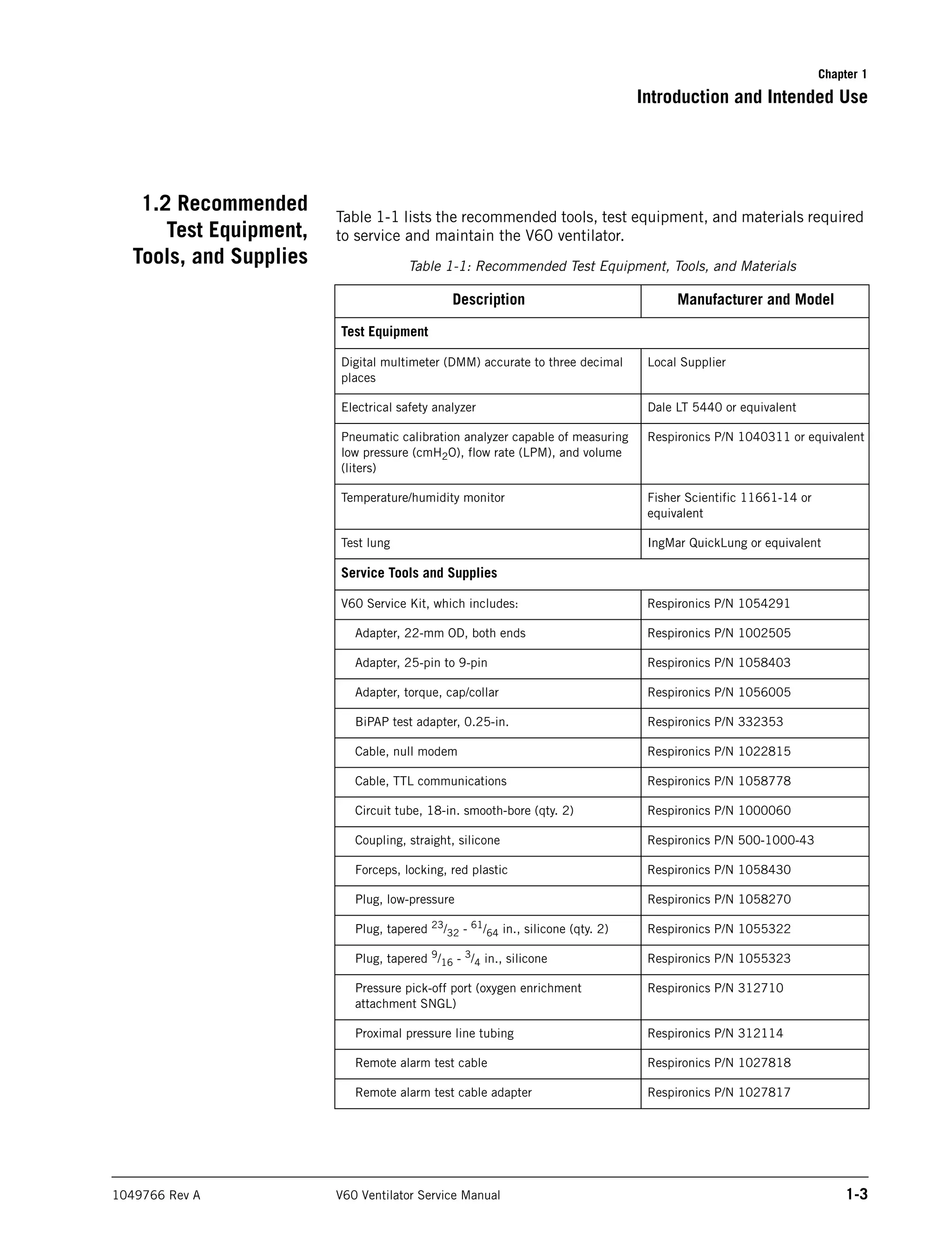
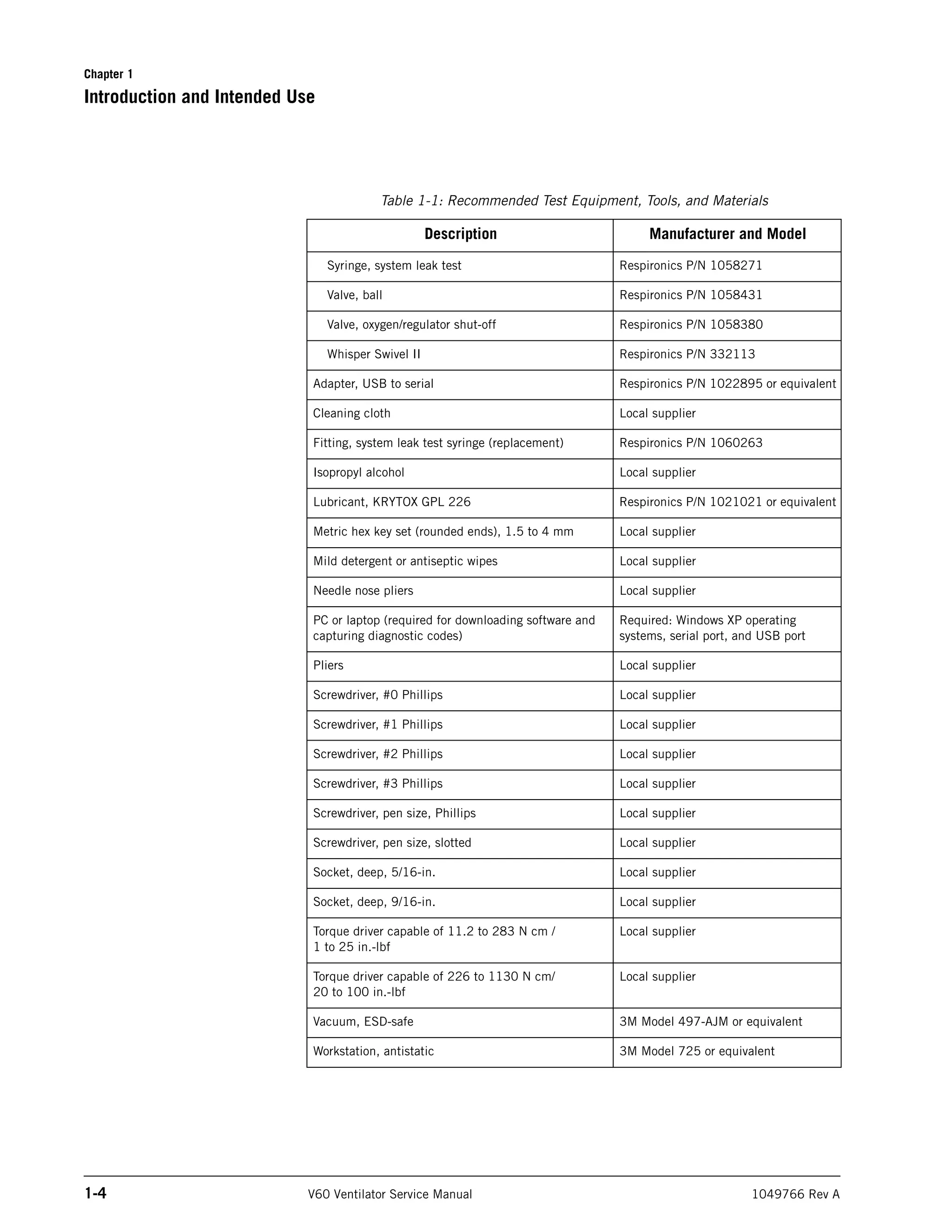
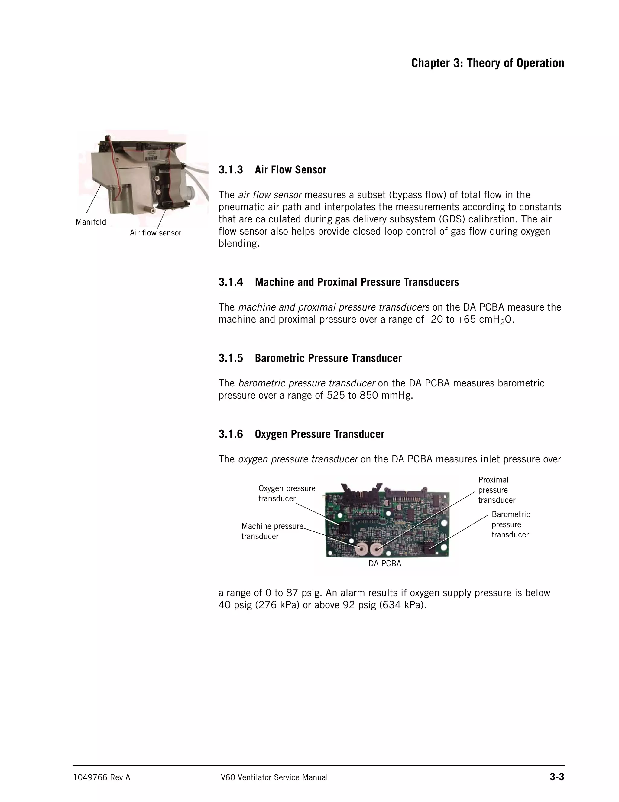
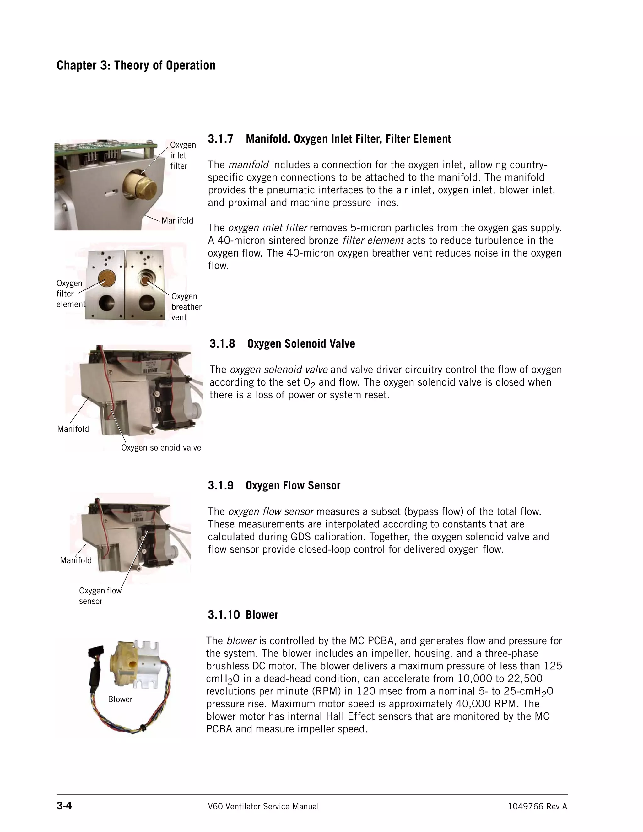
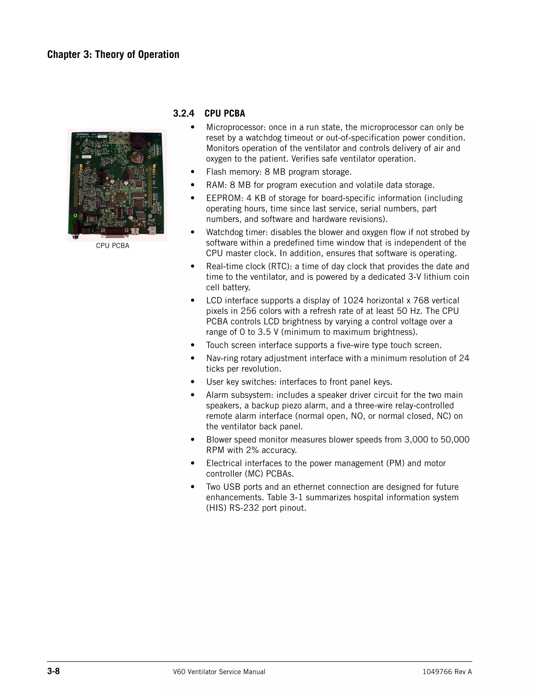
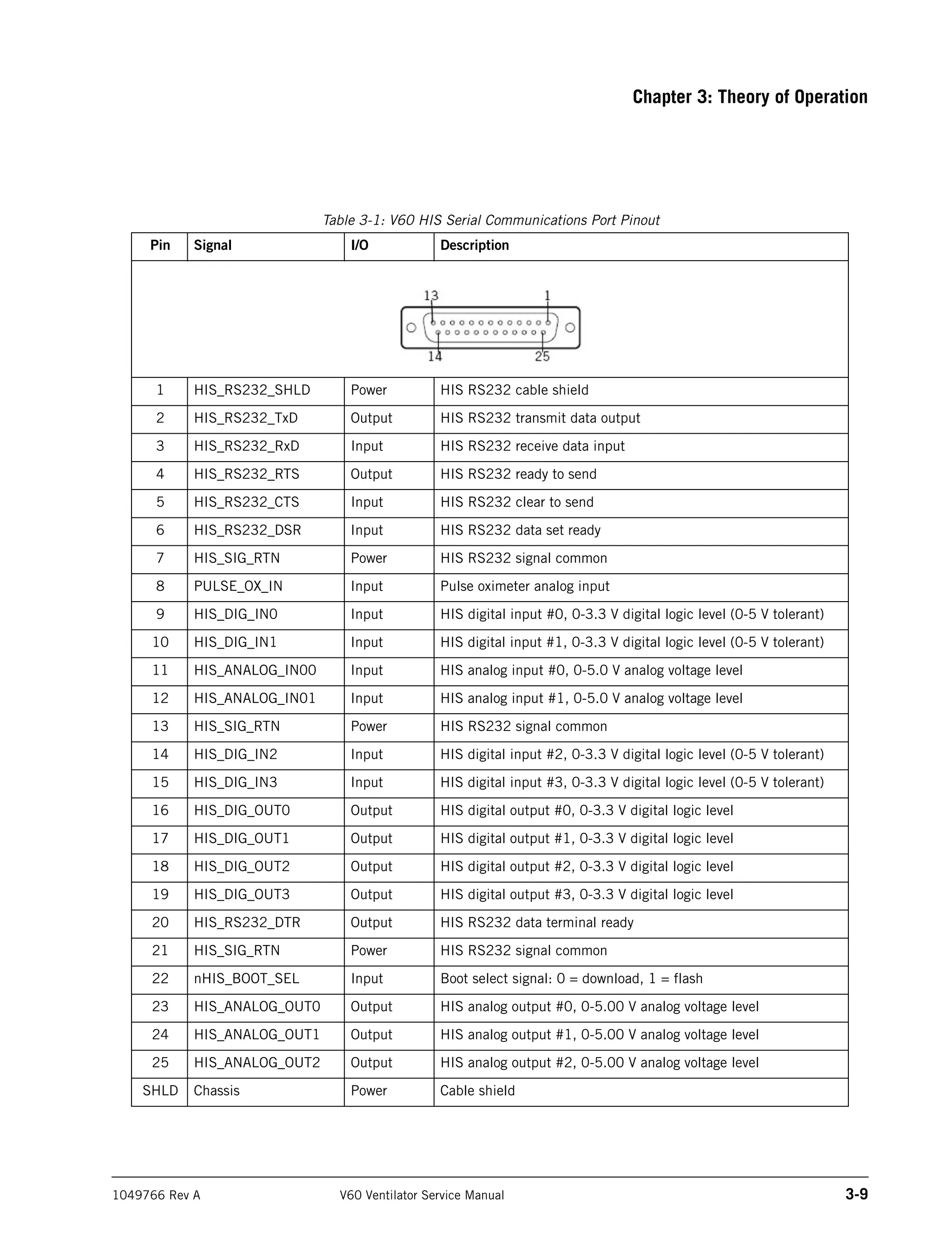
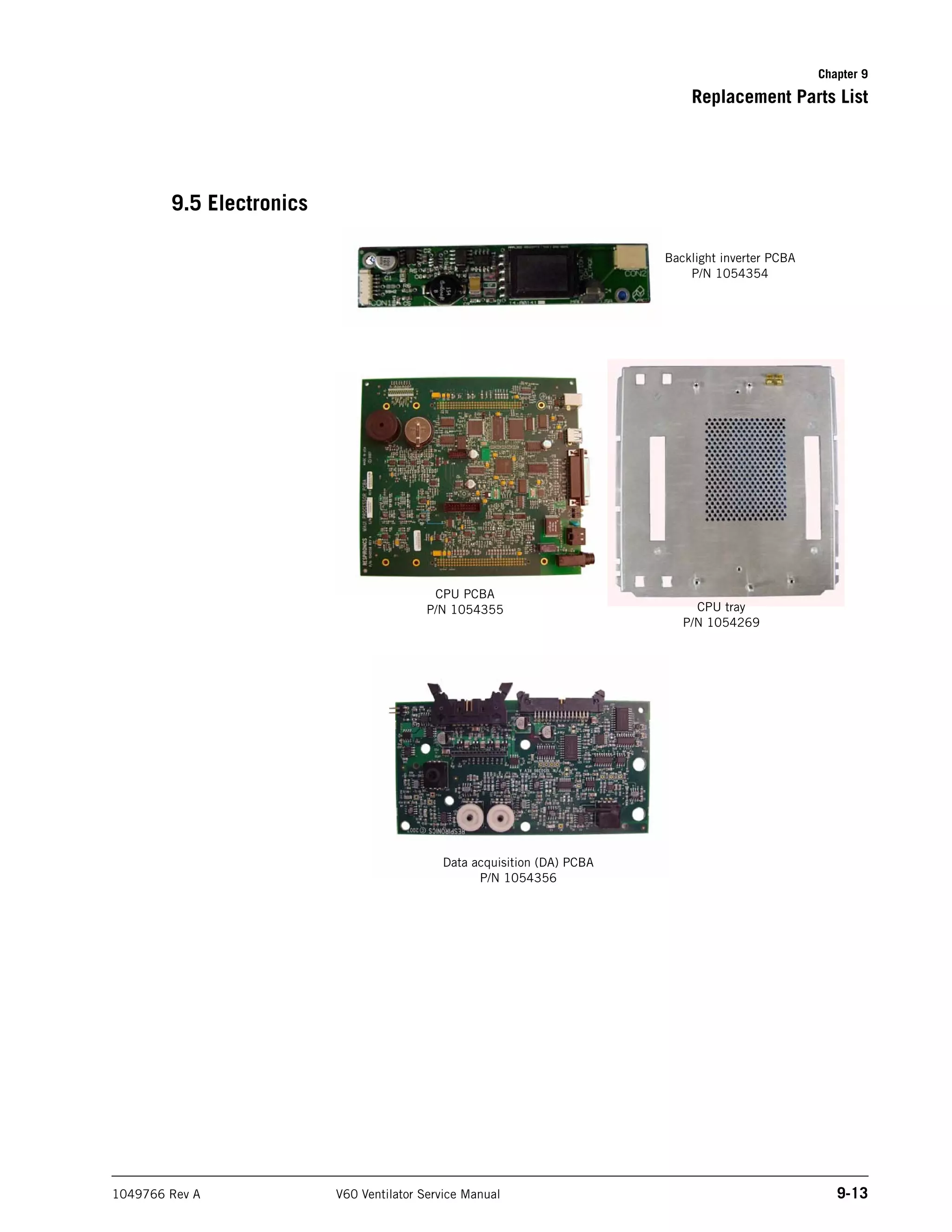
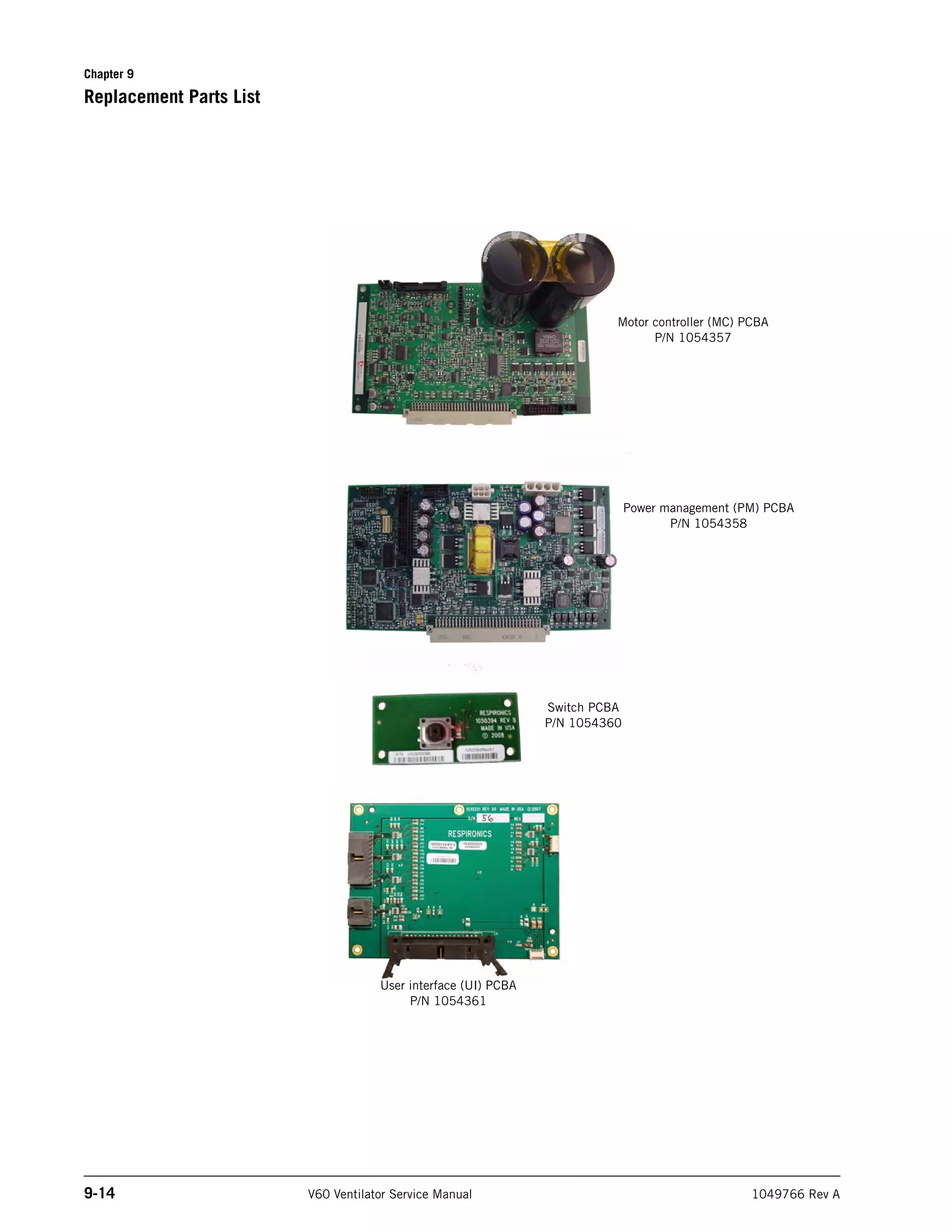
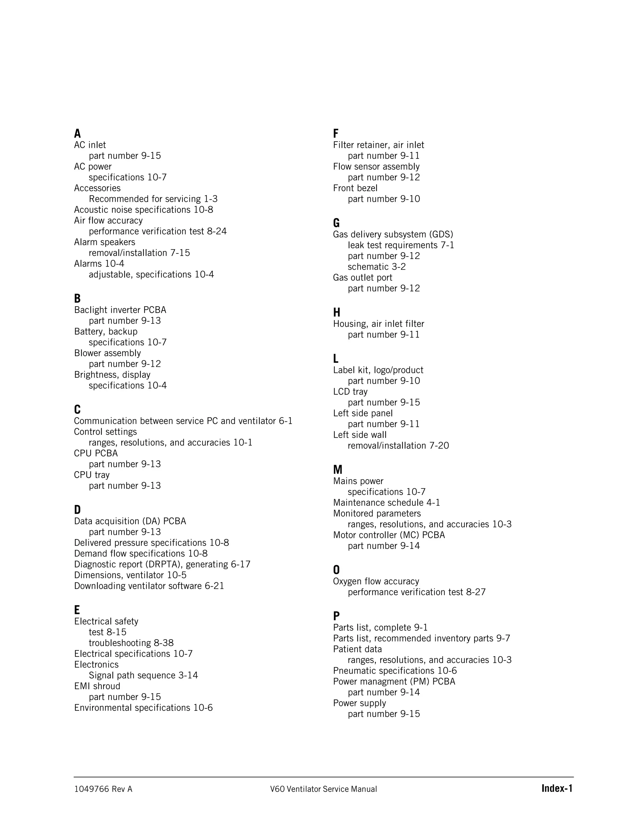
This document is the service manual for the Respironics V60 Ventilator. It provides contact information for technical support and customer service. It also outlines the intended use of the ventilator, recommended test equipment, safety warnings, theory of operation, maintenance instructions, troubleshooting steps, and procedures for generating reports and downloading software updates. The manual describes the major mechanical and electrical components of the ventilator and how to remove and install them.


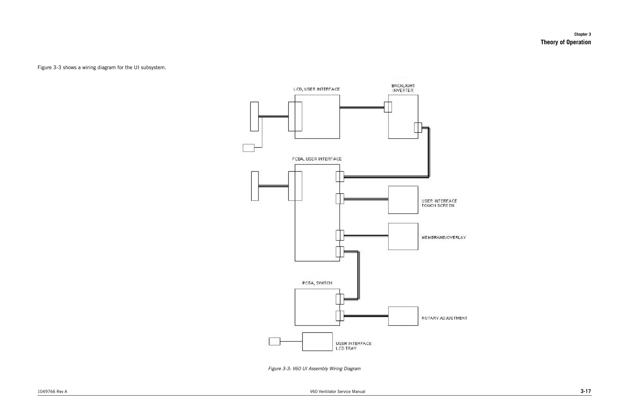


![ict_presentation_final_final_final[1].pptx](https://cdn.slidesharecdn.com/ss_thumbnails/ictpresentationfinalfinalfinal1-251230145259-2b4839bd-thumbnail.jpg?width=640&height=640&fit=bounds)

