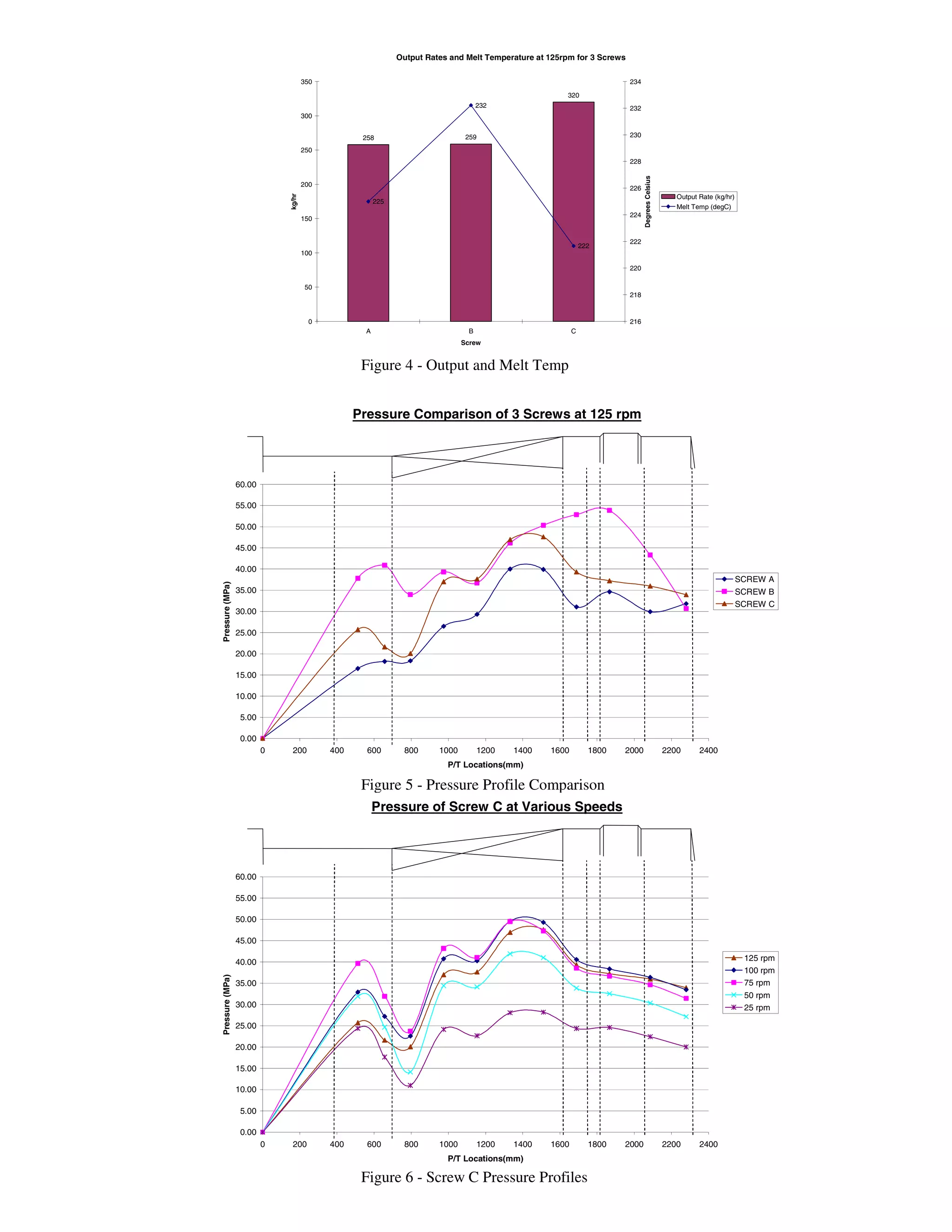
EMPIRICAL EVALUATION OF DIFFERENT GROOVE FEED SCREW
GEOMETRIES
Timothy W. Womer, Walter S. Smith and Richard P. Wheeler
Xaloy Corporation, New Castle, PA
Abstract
Plasticization rates can be greatly increased with the use
of grooved feed extrusion. Grooved feed extruders can be
used in a wide range of extrusion processes for higher
output rates. This technology has doubled plasticization
rates for some resins and processes as compared to
smooth bore extruders.
This paper will compare the performance of three
different screw geometries while processing fractional
melt HDPE. One of the main methods of evaluation will
be the comparison of internal pressure profiles over the
entire length of the screw at eleven different locations
down the length of the barrel at two L/D apart.
Introduction
Groove feed extrusion has been around for over four
decades, primarily in Europe. Most of the developmental
work in the past has been done by European Original
Equipment Manufacturers primarily in the area of
polyethylene pipe applications (1). Recently, more
emphasis has been in the area of polyethylene blown film
with a majority of the blown film extrusion equipment
built today in Europe using groove feed technology.
Early groove feed screw technology was very simple, just
as it was in the early days of smooth bore extrusion screw
designs (2). The first groove feed screws typically were
square pitch, constant depth and had some type of
distributive/ dispersive mixing at the end. These screws
typically generated very high solids conveying (3)
pressure just downstream of the grooved bushing and in
turn caused excessive screw, barrel and bushing wear.
Internal pressures as high as 100 to 300 MPa (14,500 to
45,000 psi) were typical in these early developmental
days of groove feed technology (4). As the screw
technology matured, one of the issues of concern was the
premature wear of the plasticating components.
One of the first improvements in reducing the internal
pressure was to increase the channel volume or introduce
a decompression area in the screw at the end of the
grooved bushing area. From those early design
improvements many new innovations have been
conceived to advance the technology of groove feed screw
designs.
Today, more and more U.S. companies are following the
European method of extrusion and trending towards groove
feed technology for the extrusion of polyethylene
applications, be it sheet, pipe or blow molding. This paper
will evaluate three different screw designs and evaluate their
performances based on their performances. The primary
point of performances which were evaluated in this screw
design study was the throughput rates, melt temperature and
the internal pressure generated inside of the barrel at eleven
different axial locations. (See Figure 1.)
Testing Equipment
All testing evaluations were done on a 75mm x 30:1 L/D
custom extruder. The extruder was equipped with a 112 Kw
(150hp) D.C. drive with a maximum screw speed of 129
rpm. The extruder has five water-cooled barrel zones, and
the barrel has eleven pressure transducers located
approximately every two diameters apart, starting five
diameters downstream of the feed throat opening and then
spaced axially down the length of the barrel.
The groove feed throat of the extruder has extensive
cooling, and the temperature is controlled with an
independent temperature control unit. The bore of the
groove bushing has ten equally spaced grooves which
measure 8.9mm (.350”) wide and starting at the back of the
bushing start at 3.9mm (.150”) deep and over a length of
450mm (17.688”) constantly taper to zero depth (.000”).
(See Figure 2.)
A 20/40/20 screen pack and breaker plate was used on the
discharge end of the screw. In order to have a uniform resist
pressure, a 711mm (28”) wide flex-lip sheet die was used
with the experiments. A uniform thickness of 3.175 mm
(.125”) was set on the die.
Fifteen points of data were collected during the testing
procedure. These points of data included drive amps, screw
speed (rpm), eleven internal barrel pressure points, and melt
temperature. Melt temperature was also measured using a
hand-held pyrometer.
ANTEC 2005 / 281
All data excluding the hand-held pyrometer reading was
collected on a Fluke Data Acquisition System at a rate of
100 points per second. The pressure data was then
exported into an EXCEL spreadsheet and evaluated.
Resin Used for Testing
The resin used during the evaluation was Nova Chemicals
HDPE HD-2007H with a .35 Melt index. The viscosity
versus shear rate characteristics of this resin is shown in
Figure 3.
Screw Geometry Comparison
In this study, three different screw geometries were
evaluated. All three screws were of barrier configuration
(5), but each was significantly different. The screw
geometries are briefly described to distinguish the major
differences among the three at this time. (See Table 1.)
Screw “A”
This screw design had a feed section of 80% square pitch
in the feed section, and then it opened up to a square pitch
just past the end of the groove feed bushing. The depth of
the feed section is constant in the groove feed bushing.
The depth then gradually increases into the barrier
section. The feed section then enters into a parallel
barrier section, which is 50% greater than the screw’s
square pitch, into a short square pitch metering section
before a spiral Egan-type mixer, and then a three turn
metering section at the discharge of the screw.
Screw “B”
This screw was of European-type technology. It had an
80% of square pitch lead at the beginning of the feed
section, then opened up to a square pitch flighted section.
A constant depth was used in the feed section. The
barrier section was an advancing lead barrier type section
where the main flight was 100% greater than the screw
diameter and the barrier flight was at 115% greater than
the screw diameter. The barrier section was then coupled
to a three turn metering section and then a four diameter,
12-row peg-type mixer at the end of the screw.
Screw “C”
In this screw design, it too had a feed section of 80%
square pitch in the feed section and then opened up to a
square pitch just past the end of the groove feed bushing.
The depth of the feed section is constant in the groove
feed bushing. The depth then gradually increases into the
barrier section. The feed section then enters into a
parallel barrier section, which is 72% greater than the
screw’s square pitch, into a short square pitch metering
section before a spiral Egan-type mixer, and then a two turn
metering section at the discharge of the screw.
Each of these screws had their significant differences, but
each of them was designed according to the technology
known for their individual geometries. Also, each screw’s
geometry was configured and balanced to match feed to
barrier to metering volumes. Details of these geometries
will be shown during the technical presentation.
Testing Procedure
Each screw was tested at 25, 50, 75, 100 and 125 rpm screw
speeds. At each of the screw speeds the throughput rate,
drive amperage, melt temperature and pressure profiles were
recorded. A flat profile of 232°C (450°F) was used for all
experiments. All die zones and the die adapter were set to
219°C (425°F). No screw cooling was used for the
experiments. Feed throat temperature was set at 24°C
(75°F).
Experimental Results
Throughput rate, melt temperature and pressure profiles
were recorded for all three screws. The melt temperature
was measured using the hand-held pyrometer only. Speeds
of 25, 50, 75, 100, and 125 rpm where used for each screw.
Since the maximum output of each screw was desired for
evaluation, the data for 125 rpm will be used to compare the
screws.
Please refer to Figure 4. Screw A yielded a throughput rate
of 258 kg/hr (569 lb/hr). The melt temperature from the
hand-held pyrometer was 225°C (437°F). The head
pressure created with this screw was around 30.3 MPa
(4400 psi).
An output rate of 259 kg/hr (570 lb/hr) was achieved with
Screw B. A 232°C (450°F) melt temperature was created
with this screw. The head pressure from this particular
screw was 31.0 MPa (4500 psi).
Screw C had the highest output of all three screws. The
output rate was 320 kg/hr (706 lb/hr). The polymer melt
temperature created with this screw was 222°C (431°F).
This melt temperature was the lowest of all three screws.
The head pressure was 33.1 MPa (4800 psi).
Discussion
By comparing the results in Figure 4 it can be seen that
Screw C had the best performance of all three screws.
Screw C had the highest throughput rate and lowest melt
282 / ANTEC 2005
temperature. Screws A and B had similar throughput
rates. Screw B had the highest melt temperature. This is
least desirable because more energy must be withdrawn
from the molten resin.
Pressure profile comparison for Screws A, B, and C are
found in Figure 5. Each screw has a distinct pressure
curve that correlates to the screw geometry. Screw B
generated the highest internal pressures. Screw B had the
highest pressure at the end of the feed section of 40.9
MPa (5928 psi). This can be attributed to the constant
feed depth. The other screws had a decompression
section in the feed section just after the grooves in the
barrel. More wear on the screw and barrel will be likely
to occur on Screw B in the feed section. Screw B also
had the highest pressure generated in the metering
section. The maximum pressure was 53.9 MPa (7809
psi). The barrier section had a much higher pumping
capacity versus the metering section. This causes a
restriction at the end of the barrier section and in turn
increases the melt temperature. The other screws were
designed to have a decompression at the end of the barrier
leading into the metering section. The pumping capacity
of the metering section closely matches the pumping rate
of the barrier section. This does not cause a temperature
spike. However, if the pumping capacity of the metering
section is significantly higher than the barrier section
surging will occur in the extrudate.
Since Screw C gave the most desirable results, the
pressure profiles for the various speeds for the testing are
shown in Figure 6. All five speeds show the same trend
for this screw. The biggest jump for the pressure profiles
occurred between 50 and 75 rpm.
Conclusion
Based on this extensive groove feed screw study, it is
evident that the internal pressure has a major influence on
the performance and productivity of the screw. Also,
screw geometry has a major affect on output and melt
temperature when using grooved feed technology.
Just as with smooth bore extrusion screw design, the screw
geometry for groove feed extrusion is just as important.
Therefore, by using sophisticated monitoring equipment, as
was used for this evaluation, we are able to “look” inside the
extruder and see exactly what is happening during the
feeding, melting and pumping of the groove feed extrusion
screw’s performance cycle.
References
1. Womer, Timothy, Wagner, John, Jr., Harrah, Gary,
Reber, Dean. “An Experimental Investigation on
the Influence of Barrel Temperatures on the Output
of a Constant Depth Screw With
Grooved Barrel Feeding.” SPE-ANTEC
Papers (1999).
2. Tadmor, Z. and Klein, I. Engineering Principles of
Plastic Extrusion. Van Nostrand Reinhold Co.,
1970, Chapter 5.
3. Spalding, M.A., Hyun, K.S., and Hoffman, R. “An
Experimental Investigation of Solids Conveying in
Smooth and Grooved Barrel Single-Screw
Plasticating Extruders.” SPE-ANTEC. Papers, 44,
136 (1998).
4. Rauwendaal, Chris. Polymer Extrusion. Hanser
Publishers, 1986, Chapter 7.
5. Womer, Timothy, W., Harrah, Gary. “An
Empirical Study for the Optimization of the Barrier
Flight Clearance for Single Stage Extrusion Using
Design of Experiment.” SPE-ANTEC Papers,
(1998).
Keywords
Extrusion, Groove feed, Barrier-type screws
ANTEC 2005 / 283
Dimension
Screw
"A"
Screw
"B"
Screw
"C"
1st Feed Depth 0.271 0.276 0.365
1st Feed Pitch 2.362 2.344 2.362
2nd Feed Pitch 2.953 2.917 2.953
Barrier Pitch 4.429 6.359 5.091
1st Metering
Depth 0.283 0.361 0.351
1st Metering
Pitch 2.953 2.917 2.953
Mixer Type
Egan
Type
Pin
Type
Egan
Type
2nd Metering
Depth 0.283 0.361 0.351
2nd Metering
Pitch 2.953 2.917 2.953
Figure 2 - Grooved Feed Bushing
Figure 3 - Viscosity Curve
Figure 1 – P/T Location
Table 1 – Screw Geometry
Novapol HD-2007H Viscosity
100
1000
10000
10 100 1000 10000
Apparent Shear Rate (1/sec)
ApparentShearViscosity(Pa*sec)
216 degC
221 degC
232 degC
284 / ANTEC 2005
Pressure of Screw C at Various Speeds
0.00
5.00
10.00
15.00
20.00
25.00
30.00
35.00
40.00
45.00
50.00
55.00
60.00
0 200 400 600 800 1000 1200 1400 1600 1800 2000 2200 2400
P/T Locations(mm)
Pressure(MPa)
125 rpm
100 rpm
75 rpm
50 rpm
25 rpm
Figure 4 - Output and Melt Temp
Figure 5 - Pressure Profile Comparison
Figure 6 - Screw C Pressure Profiles
Output Rates and Melt Temperature at 125rpm for 3 Screws
258 259
320
225
232
222
0
50
100
150
200
250
300
350
A B C
Screw
kg/hr
216
218
220
222
224
226
228
230
232
234
DegreesCelsius
Output Rate (kg/hr)
Melt Temp (degC)
Pressure Comparison of 3 Screws at 125 rpm
0.00
5.00
10.00
15.00
20.00
25.00
30.00
35.00
40.00
45.00
50.00
55.00
60.00
0 200 400 600 800 1000 1200 1400 1600 1800 2000 2200 2400
P/T Locations(mm)
Pressure(MPa)
SCREW A
SCREW B
SCREW C
ANTEC 2005 / 285

Empirical evaluation of different groove feed screw geometries

  • 1.
    EMPIRICAL EVALUATION OFDIFFERENT GROOVE FEED SCREW GEOMETRIES Timothy W. Womer, Walter S. Smith and Richard P. Wheeler Xaloy Corporation, New Castle, PA Abstract Plasticization rates can be greatly increased with the use of grooved feed extrusion. Grooved feed extruders can be used in a wide range of extrusion processes for higher output rates. This technology has doubled plasticization rates for some resins and processes as compared to smooth bore extruders. This paper will compare the performance of three different screw geometries while processing fractional melt HDPE. One of the main methods of evaluation will be the comparison of internal pressure profiles over the entire length of the screw at eleven different locations down the length of the barrel at two L/D apart. Introduction Groove feed extrusion has been around for over four decades, primarily in Europe. Most of the developmental work in the past has been done by European Original Equipment Manufacturers primarily in the area of polyethylene pipe applications (1). Recently, more emphasis has been in the area of polyethylene blown film with a majority of the blown film extrusion equipment built today in Europe using groove feed technology. Early groove feed screw technology was very simple, just as it was in the early days of smooth bore extrusion screw designs (2). The first groove feed screws typically were square pitch, constant depth and had some type of distributive/ dispersive mixing at the end. These screws typically generated very high solids conveying (3) pressure just downstream of the grooved bushing and in turn caused excessive screw, barrel and bushing wear. Internal pressures as high as 100 to 300 MPa (14,500 to 45,000 psi) were typical in these early developmental days of groove feed technology (4). As the screw technology matured, one of the issues of concern was the premature wear of the plasticating components. One of the first improvements in reducing the internal pressure was to increase the channel volume or introduce a decompression area in the screw at the end of the grooved bushing area. From those early design improvements many new innovations have been conceived to advance the technology of groove feed screw designs. Today, more and more U.S. companies are following the European method of extrusion and trending towards groove feed technology for the extrusion of polyethylene applications, be it sheet, pipe or blow molding. This paper will evaluate three different screw designs and evaluate their performances based on their performances. The primary point of performances which were evaluated in this screw design study was the throughput rates, melt temperature and the internal pressure generated inside of the barrel at eleven different axial locations. (See Figure 1.) Testing Equipment All testing evaluations were done on a 75mm x 30:1 L/D custom extruder. The extruder was equipped with a 112 Kw (150hp) D.C. drive with a maximum screw speed of 129 rpm. The extruder has five water-cooled barrel zones, and the barrel has eleven pressure transducers located approximately every two diameters apart, starting five diameters downstream of the feed throat opening and then spaced axially down the length of the barrel. The groove feed throat of the extruder has extensive cooling, and the temperature is controlled with an independent temperature control unit. The bore of the groove bushing has ten equally spaced grooves which measure 8.9mm (.350”) wide and starting at the back of the bushing start at 3.9mm (.150”) deep and over a length of 450mm (17.688”) constantly taper to zero depth (.000”). (See Figure 2.) A 20/40/20 screen pack and breaker plate was used on the discharge end of the screw. In order to have a uniform resist pressure, a 711mm (28”) wide flex-lip sheet die was used with the experiments. A uniform thickness of 3.175 mm (.125”) was set on the die. Fifteen points of data were collected during the testing procedure. These points of data included drive amps, screw speed (rpm), eleven internal barrel pressure points, and melt temperature. Melt temperature was also measured using a hand-held pyrometer. ANTEC 2005 / 281
  • 2.
    All data excludingthe hand-held pyrometer reading was collected on a Fluke Data Acquisition System at a rate of 100 points per second. The pressure data was then exported into an EXCEL spreadsheet and evaluated. Resin Used for Testing The resin used during the evaluation was Nova Chemicals HDPE HD-2007H with a .35 Melt index. The viscosity versus shear rate characteristics of this resin is shown in Figure 3. Screw Geometry Comparison In this study, three different screw geometries were evaluated. All three screws were of barrier configuration (5), but each was significantly different. The screw geometries are briefly described to distinguish the major differences among the three at this time. (See Table 1.) Screw “A” This screw design had a feed section of 80% square pitch in the feed section, and then it opened up to a square pitch just past the end of the groove feed bushing. The depth of the feed section is constant in the groove feed bushing. The depth then gradually increases into the barrier section. The feed section then enters into a parallel barrier section, which is 50% greater than the screw’s square pitch, into a short square pitch metering section before a spiral Egan-type mixer, and then a three turn metering section at the discharge of the screw. Screw “B” This screw was of European-type technology. It had an 80% of square pitch lead at the beginning of the feed section, then opened up to a square pitch flighted section. A constant depth was used in the feed section. The barrier section was an advancing lead barrier type section where the main flight was 100% greater than the screw diameter and the barrier flight was at 115% greater than the screw diameter. The barrier section was then coupled to a three turn metering section and then a four diameter, 12-row peg-type mixer at the end of the screw. Screw “C” In this screw design, it too had a feed section of 80% square pitch in the feed section and then opened up to a square pitch just past the end of the groove feed bushing. The depth of the feed section is constant in the groove feed bushing. The depth then gradually increases into the barrier section. The feed section then enters into a parallel barrier section, which is 72% greater than the screw’s square pitch, into a short square pitch metering section before a spiral Egan-type mixer, and then a two turn metering section at the discharge of the screw. Each of these screws had their significant differences, but each of them was designed according to the technology known for their individual geometries. Also, each screw’s geometry was configured and balanced to match feed to barrier to metering volumes. Details of these geometries will be shown during the technical presentation. Testing Procedure Each screw was tested at 25, 50, 75, 100 and 125 rpm screw speeds. At each of the screw speeds the throughput rate, drive amperage, melt temperature and pressure profiles were recorded. A flat profile of 232°C (450°F) was used for all experiments. All die zones and the die adapter were set to 219°C (425°F). No screw cooling was used for the experiments. Feed throat temperature was set at 24°C (75°F). Experimental Results Throughput rate, melt temperature and pressure profiles were recorded for all three screws. The melt temperature was measured using the hand-held pyrometer only. Speeds of 25, 50, 75, 100, and 125 rpm where used for each screw. Since the maximum output of each screw was desired for evaluation, the data for 125 rpm will be used to compare the screws. Please refer to Figure 4. Screw A yielded a throughput rate of 258 kg/hr (569 lb/hr). The melt temperature from the hand-held pyrometer was 225°C (437°F). The head pressure created with this screw was around 30.3 MPa (4400 psi). An output rate of 259 kg/hr (570 lb/hr) was achieved with Screw B. A 232°C (450°F) melt temperature was created with this screw. The head pressure from this particular screw was 31.0 MPa (4500 psi). Screw C had the highest output of all three screws. The output rate was 320 kg/hr (706 lb/hr). The polymer melt temperature created with this screw was 222°C (431°F). This melt temperature was the lowest of all three screws. The head pressure was 33.1 MPa (4800 psi). Discussion By comparing the results in Figure 4 it can be seen that Screw C had the best performance of all three screws. Screw C had the highest throughput rate and lowest melt 282 / ANTEC 2005
  • 3.
    temperature. Screws Aand B had similar throughput rates. Screw B had the highest melt temperature. This is least desirable because more energy must be withdrawn from the molten resin. Pressure profile comparison for Screws A, B, and C are found in Figure 5. Each screw has a distinct pressure curve that correlates to the screw geometry. Screw B generated the highest internal pressures. Screw B had the highest pressure at the end of the feed section of 40.9 MPa (5928 psi). This can be attributed to the constant feed depth. The other screws had a decompression section in the feed section just after the grooves in the barrel. More wear on the screw and barrel will be likely to occur on Screw B in the feed section. Screw B also had the highest pressure generated in the metering section. The maximum pressure was 53.9 MPa (7809 psi). The barrier section had a much higher pumping capacity versus the metering section. This causes a restriction at the end of the barrier section and in turn increases the melt temperature. The other screws were designed to have a decompression at the end of the barrier leading into the metering section. The pumping capacity of the metering section closely matches the pumping rate of the barrier section. This does not cause a temperature spike. However, if the pumping capacity of the metering section is significantly higher than the barrier section surging will occur in the extrudate. Since Screw C gave the most desirable results, the pressure profiles for the various speeds for the testing are shown in Figure 6. All five speeds show the same trend for this screw. The biggest jump for the pressure profiles occurred between 50 and 75 rpm. Conclusion Based on this extensive groove feed screw study, it is evident that the internal pressure has a major influence on the performance and productivity of the screw. Also, screw geometry has a major affect on output and melt temperature when using grooved feed technology. Just as with smooth bore extrusion screw design, the screw geometry for groove feed extrusion is just as important. Therefore, by using sophisticated monitoring equipment, as was used for this evaluation, we are able to “look” inside the extruder and see exactly what is happening during the feeding, melting and pumping of the groove feed extrusion screw’s performance cycle. References 1. Womer, Timothy, Wagner, John, Jr., Harrah, Gary, Reber, Dean. “An Experimental Investigation on the Influence of Barrel Temperatures on the Output of a Constant Depth Screw With Grooved Barrel Feeding.” SPE-ANTEC Papers (1999). 2. Tadmor, Z. and Klein, I. Engineering Principles of Plastic Extrusion. Van Nostrand Reinhold Co., 1970, Chapter 5. 3. Spalding, M.A., Hyun, K.S., and Hoffman, R. “An Experimental Investigation of Solids Conveying in Smooth and Grooved Barrel Single-Screw Plasticating Extruders.” SPE-ANTEC. Papers, 44, 136 (1998). 4. Rauwendaal, Chris. Polymer Extrusion. Hanser Publishers, 1986, Chapter 7. 5. Womer, Timothy, W., Harrah, Gary. “An Empirical Study for the Optimization of the Barrier Flight Clearance for Single Stage Extrusion Using Design of Experiment.” SPE-ANTEC Papers, (1998). Keywords Extrusion, Groove feed, Barrier-type screws ANTEC 2005 / 283
  • 4.
    Dimension Screw "A" Screw "B" Screw "C" 1st Feed Depth0.271 0.276 0.365 1st Feed Pitch 2.362 2.344 2.362 2nd Feed Pitch 2.953 2.917 2.953 Barrier Pitch 4.429 6.359 5.091 1st Metering Depth 0.283 0.361 0.351 1st Metering Pitch 2.953 2.917 2.953 Mixer Type Egan Type Pin Type Egan Type 2nd Metering Depth 0.283 0.361 0.351 2nd Metering Pitch 2.953 2.917 2.953 Figure 2 - Grooved Feed Bushing Figure 3 - Viscosity Curve Figure 1 – P/T Location Table 1 – Screw Geometry Novapol HD-2007H Viscosity 100 1000 10000 10 100 1000 10000 Apparent Shear Rate (1/sec) ApparentShearViscosity(Pa*sec) 216 degC 221 degC 232 degC 284 / ANTEC 2005
  • 5.
    Pressure of ScrewC at Various Speeds 0.00 5.00 10.00 15.00 20.00 25.00 30.00 35.00 40.00 45.00 50.00 55.00 60.00 0 200 400 600 800 1000 1200 1400 1600 1800 2000 2200 2400 P/T Locations(mm) Pressure(MPa) 125 rpm 100 rpm 75 rpm 50 rpm 25 rpm Figure 4 - Output and Melt Temp Figure 5 - Pressure Profile Comparison Figure 6 - Screw C Pressure Profiles Output Rates and Melt Temperature at 125rpm for 3 Screws 258 259 320 225 232 222 0 50 100 150 200 250 300 350 A B C Screw kg/hr 216 218 220 222 224 226 228 230 232 234 DegreesCelsius Output Rate (kg/hr) Melt Temp (degC) Pressure Comparison of 3 Screws at 125 rpm 0.00 5.00 10.00 15.00 20.00 25.00 30.00 35.00 40.00 45.00 50.00 55.00 60.00 0 200 400 600 800 1000 1200 1400 1600 1800 2000 2200 2400 P/T Locations(mm) Pressure(MPa) SCREW A SCREW B SCREW C ANTEC 2005 / 285