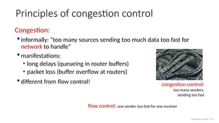
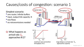
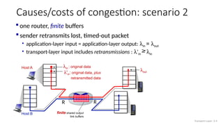
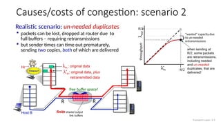
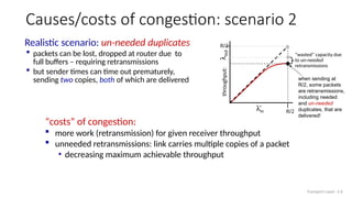
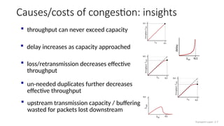
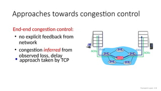
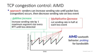
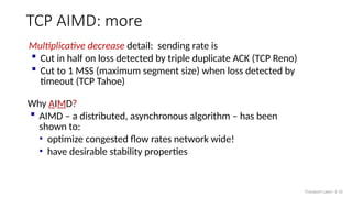
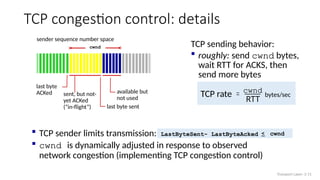
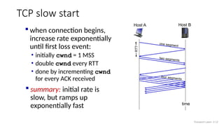
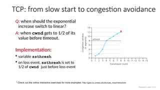
IT 305
Computer Networks
Week7 – Lec1
TCP Congestion Control
Congestion:
 informally: “too many sources sending too much data too fast for
network to handle”
 manifestations:
• long delays (queueing in router buffers)
• packet loss (buffer overflow at routers)
 different from flow control!
Principles of congestion control
congestion control:
too many senders,
sending too fast
Transport Layer: 3-2
flow control: one sender too fast for one receiver
Causes/costs of congestion: scenario 1
Simplest scenario:
maximum per-connection
throughput: R/2
Host A
Host B
throughput: lout
large delays as arrival rate
approaches capacity
Q: What happens as
arrival rate lin
approaches R/2?
original data: lin
R
 two flows
 one router, infinite buffers
 input, output link capacity: R infinite shared
output link buffers
R
 no retransmissions needed
R/2
delay
lin
R/2
R/2
l
out
lin
throughput:
Transport Layer: 3-3
lin
Causes/costs of congestion: scenario 2
 one router, finite buffers
Host A
Host B
lin : original data
l'in: original data, plus
retransmitted data
finite shared output
link buffers
 sender retransmits lost, timed-out packet
• application-layer input = application-layer output: lin = lout
• transport-layer input includes retransmissions : l’in lin
lout
R
R
Transport Layer: 3-4
Host A
Host B
lin : original data
l'in: original data, plus
retransmitted data
finite shared output
link buffers
R
R
Causes/costs of congestion: scenario 2
copy
timeout
Realistic scenario: un-needed duplicates
 packets can be lost, dropped at router due to
full buffers – requiring retransmissions
 but sender times can time out prematurely,
sending two copies, both of which are delivered
free buffer space!
when sending at
R/2, some packets
are retransmissions,
including needed
and un-needed
duplicates, that are
delivered!
“wasted” capacity due
to un-needed
retransmissions
lin
R/2
l
out
throughput:
R/2
Transport Layer: 3-5
Causes/costs of congestion: scenario 2
“costs” of congestion:
 more work (retransmission) for given receiver throughput
 unneeded retransmissions: link carries multiple copies of a packet
• decreasing maximum achievable throughput
Realistic scenario: un-needed duplicates
 packets can be lost, dropped at router due to
full buffers – requiring retransmissions
 but sender times can time out prematurely,
sending two copies, both of which are delivered when sending at
R/2, some packets
are retransmissions,
including needed
and un-needed
duplicates, that are
delivered!
“wasted” capacity due
to un-needed
retransmissions
lin
R/2
l
out
throughput:
R/2
Transport Layer: 3-6
Causes/costs of congestion: insights
 upstream transmission capacity / buffering
wasted for packets lost downstream
 delay increases as capacity approached
 un-needed duplicates further decreases
effective throughput
 loss/retransmission decreases effective
throughput
 throughput can never exceed capacity
Transport Layer: 3-7
End-end congestion control:
• no explicit feedback from
network
• congestion inferred from
observed loss, delay
Approaches towards congestion control
data
data
ACKs
ACKs
 approach taken by TCP
Transport Layer: 3-8
TCP congestion control: AIMD
 approach: senders can increase sending rate until packet loss
(congestion) occurs, then decrease sending rate on loss event
AIMD sawtooth
behavior: probing
for bandwidth
TCP
sender
Sending
rate
time
increase sending rate by 1
maximum segment size every
RTT until loss detected
Additive Increase
cut sending rate in half at
each loss event
Multiplicative Decrease
Transport Layer: 3-9
TCP AIMD: more
Multiplicative decrease detail: sending rate is
 Cut in half on loss detected by triple duplicate ACK (TCP Reno)
 Cut to 1 MSS (maximum segment size) when loss detected by
timeout (TCP Tahoe)
Why AIMD?
 AIMD – a distributed, asynchronous algorithm – has been
shown to:
• optimize congested flow rates network wide!
• have desirable stability properties
Transport Layer: 3-10
TCP congestion control: details
 TCP sender limits transmission:
 cwnd is dynamically adjusted in response to observed
network congestion (implementing TCP congestion control)
LastByteSent- LastByteAcked < cwnd
last byte
ACKed
last byte sent
cwnd
sender sequence number space
available but
not used
TCP sending behavior:
 roughly: send cwnd bytes,
wait RTT for ACKS, then
send more bytes
TCP rate ~
~
cwnd
RTT
bytes/sec
sent, but not-
yet ACKed
(“in-flight”)
Transport Layer: 3-11
TCP slow start
 when connection begins,
increase rate exponentially
until first loss event:
• initially cwnd = 1 MSS
• double cwnd every RTT
• done by incrementing cwnd
for every ACK received
Host A
one segment
Host B
RTT
time
two segments
four segments
 summary: initial rate is
slow, but ramps up
exponentially fast
Transport Layer: 3-12
TCP: from slow start to congestion avoidance
Q: when should the exponential
increase switch to linear?
A: when cwnd gets to 1/2 of its
value before timeout.
Implementation:
 variable ssthresh
 on loss event, ssthresh is set to
1/2 of cwnd just before loss event
* Check out the online interactive exercises for more examples: http://gaia.cs.umass.edu/kurose_ross/interactive/
X
Transport Layer: 3-13

Computer Networks_Lec 1-TCP Congestion .pptx

  • 1.
    IT 305 Computer Networks Week7– Lec1 TCP Congestion Control
  • 2.
    Congestion:  informally: “toomany sources sending too much data too fast for network to handle”  manifestations: • long delays (queueing in router buffers) • packet loss (buffer overflow at routers)  different from flow control! Principles of congestion control congestion control: too many senders, sending too fast Transport Layer: 3-2 flow control: one sender too fast for one receiver
  • 3.
    Causes/costs of congestion:scenario 1 Simplest scenario: maximum per-connection throughput: R/2 Host A Host B throughput: lout large delays as arrival rate approaches capacity Q: What happens as arrival rate lin approaches R/2? original data: lin R  two flows  one router, infinite buffers  input, output link capacity: R infinite shared output link buffers R  no retransmissions needed R/2 delay lin R/2 R/2 l out lin throughput: Transport Layer: 3-3 lin
  • 4.
    Causes/costs of congestion:scenario 2  one router, finite buffers Host A Host B lin : original data l'in: original data, plus retransmitted data finite shared output link buffers  sender retransmits lost, timed-out packet • application-layer input = application-layer output: lin = lout • transport-layer input includes retransmissions : l’in lin lout R R Transport Layer: 3-4
  • 5.
    Host A Host B lin: original data l'in: original data, plus retransmitted data finite shared output link buffers R R Causes/costs of congestion: scenario 2 copy timeout Realistic scenario: un-needed duplicates  packets can be lost, dropped at router due to full buffers – requiring retransmissions  but sender times can time out prematurely, sending two copies, both of which are delivered free buffer space! when sending at R/2, some packets are retransmissions, including needed and un-needed duplicates, that are delivered! “wasted” capacity due to un-needed retransmissions lin R/2 l out throughput: R/2 Transport Layer: 3-5
  • 6.
    Causes/costs of congestion:scenario 2 “costs” of congestion:  more work (retransmission) for given receiver throughput  unneeded retransmissions: link carries multiple copies of a packet • decreasing maximum achievable throughput Realistic scenario: un-needed duplicates  packets can be lost, dropped at router due to full buffers – requiring retransmissions  but sender times can time out prematurely, sending two copies, both of which are delivered when sending at R/2, some packets are retransmissions, including needed and un-needed duplicates, that are delivered! “wasted” capacity due to un-needed retransmissions lin R/2 l out throughput: R/2 Transport Layer: 3-6
  • 7.
    Causes/costs of congestion:insights  upstream transmission capacity / buffering wasted for packets lost downstream  delay increases as capacity approached  un-needed duplicates further decreases effective throughput  loss/retransmission decreases effective throughput  throughput can never exceed capacity Transport Layer: 3-7
  • 8.
    End-end congestion control: •no explicit feedback from network • congestion inferred from observed loss, delay Approaches towards congestion control data data ACKs ACKs  approach taken by TCP Transport Layer: 3-8
  • 9.
    TCP congestion control:AIMD  approach: senders can increase sending rate until packet loss (congestion) occurs, then decrease sending rate on loss event AIMD sawtooth behavior: probing for bandwidth TCP sender Sending rate time increase sending rate by 1 maximum segment size every RTT until loss detected Additive Increase cut sending rate in half at each loss event Multiplicative Decrease Transport Layer: 3-9
  • 10.
    TCP AIMD: more Multiplicativedecrease detail: sending rate is  Cut in half on loss detected by triple duplicate ACK (TCP Reno)  Cut to 1 MSS (maximum segment size) when loss detected by timeout (TCP Tahoe) Why AIMD?  AIMD – a distributed, asynchronous algorithm – has been shown to: • optimize congested flow rates network wide! • have desirable stability properties Transport Layer: 3-10
  • 11.
    TCP congestion control:details  TCP sender limits transmission:  cwnd is dynamically adjusted in response to observed network congestion (implementing TCP congestion control) LastByteSent- LastByteAcked < cwnd last byte ACKed last byte sent cwnd sender sequence number space available but not used TCP sending behavior:  roughly: send cwnd bytes, wait RTT for ACKS, then send more bytes TCP rate ~ ~ cwnd RTT bytes/sec sent, but not- yet ACKed (“in-flight”) Transport Layer: 3-11
  • 12.
    TCP slow start when connection begins, increase rate exponentially until first loss event: • initially cwnd = 1 MSS • double cwnd every RTT • done by incrementing cwnd for every ACK received Host A one segment Host B RTT time two segments four segments  summary: initial rate is slow, but ramps up exponentially fast Transport Layer: 3-12
  • 13.
    TCP: from slowstart to congestion avoidance Q: when should the exponential increase switch to linear? A: when cwnd gets to 1/2 of its value before timeout. Implementation:  variable ssthresh  on loss event, ssthresh is set to 1/2 of cwnd just before loss event * Check out the online interactive exercises for more examples: http://gaia.cs.umass.edu/kurose_ross/interactive/ X Transport Layer: 3-13