The document presents a comparative analysis of various linear controllers used in grid-connected photovoltaic (PV) systems, emphasizing the importance of efficient inverters for converting generated DC power to AC power for grid integration. It details the challenges and methods for tracking grid synchronization, and compares proportional-integral (PI) controllers with proportional-resonant (PR) controllers, highlighting their advantages and disadvantages. Experimental results from a prototype inverter demonstrate the effectiveness of the proposed optimized PID controller in achieving efficient power conversion.


![Int J Elec & Comp Eng ISSN: 2088-8708
Comparative Analysis of Linear Controllers used for Grid Connected (Ritesh Das)
519
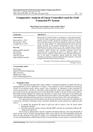
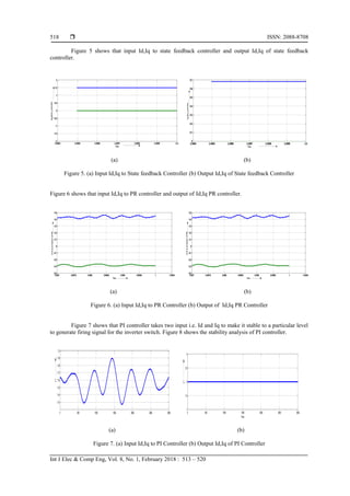
Figure 9 shows the stability analysis of PR controller.
Figure 10 shows the stability analysis of state feedback controller.
Figure 8. Stability Analysis of PI Controller Figure 9. Stability analysis of PR Controller
Figure 10. Stability analysis of State feedback Controller
4. CONCLUSION
Evaluation of the linear controller has been carried out under a steady state condition. Power
injected into the grid is maintained at aparticular level by fixing the voltage. Current injection quantity has
been increasesd by applying different controller. Stability analysis of all the discussed controller has been
presented with Nyquist plot to check the stability.Best on the result PI controller is found to be best one under
non transient condition. PR- controller shows high gain around the resonance frequency thereby increasing
the grid current injection level and real power transmission.
ACKNOWLEDGEMENT
Authors would like to give thanks to the school of electrical engineering for providing necessary
laboratory arrangement and experimental setup to carry out the experiment on linear controller.
REFERENCES
[1] R. M. Essefi, M. Souissi and H. H. Abdallah, "Linear current control technique for grid connected photovoltaic
system," Sciences and Techniques of Automatic Control and Computer Engineering (STA), 2013 14th International
Conference on, Sousse, 2013, pp. 432-437.
[2] H.H. Sait, S.A. Daniel, “New control paradigm for integration of photovoltaic energy sources with utility network,”
International journal of Electrical Power & Energy Systems, Vol. 33(Issue 1):86-93, January 2011.
[3] G. Shen, D. Xu, L. Cao, X. Zhu, “An Improved Control Strategy for Grid-Connected Voltage Source Inverters
With an LCL Filter,” IEEE Transactions on Power Electronics, Vol. 23(Issue 4):1899-1906, July 2008.
-1 -0.5 0 0.5
-0.4
-0.3
-0.2
-0.1
0
0.1
0.2
0.3
0.4
0 dB
-20 dB
-10 dB-6 dB-4 dB-2 dB
20 dB
10 dB
6 dB 4 dB 2 dB
Nyquist Diagram
Real Axis
ImaginaryAxis
-2.5 -2 -1.5 -1 -0.5 0 0.5 1
-2.5
-2
-1.5
-1
-0.5
0
0.5
1
1.5
2
2.5
0 dB
-20 dB
-10 dB
-6 dB
-4 dB
-2 dB
20 dB
10 dB
6 dB
4 dB
2 dB
System: H
Real: -0.347
Imag: -2.02
Frequency (rad/s): -0.000415
NyquistDiagram
RealAxis
ImaginaryAxis
-5 -4 -3 -2 -1 0 1 2 3 4
-8
-6
-4
-2
0
2
4
6
8
0 dB
-10 dB
-6 dB
-4 dB
-2 dB
10 dB
6 dB
4 dB
2 dB
NyquistDiagram
RealAxis
ImaginaryAxis](https://image.slidesharecdn.com/v5527dec1712oct10659-13671-1-smedittyas-201106061700/85/Comparative-Analysis-of-Linear-Controllers-used-for-Grid-Connected-PV-System-7-320.jpg)
![ ISSN: 2088-8708
Int J Elec & Comp Eng, Vol. 8, No. 1, February 2018 : 513 – 520
520
[4] S. Fukuda, T. Yoda, "A novel current-tracking method for active filters based on a sinusoidal internal model", IEEE
Trans. Ind. Appl., vol. 37, no. 3, pp. 888-895, May/Jun. 2001.
[5] M. Liserre, R. Teodorescu, F. Blaabjerg, "Stability of photovoltaic and wind turbine grid-connected inverters for a
large set of grid impedance values", IEEE Trans. Power Electron., vol. 21, no. 1, pp. 263-272, Jan. 2006.
[6] M. Liserre, F. Blaabjerg, S. Hansen, "Design and control of an LCL-filter based active rectifier", IEEE Trans. Ind.
Appl., vol. 41, no. 5, pp. 1281-1291, Sep./Oct. 2005.
[7] M. Liserre, R. Teodorescu, F. Blaabjerg, "Multiple harmonics control for three-phase grid converter systems with
the use of PI-RES current controller in a rotating frame", IEEE Trans. Power Electron., vol. 21, no. 3, pp. 836-841,
May 2006.
[8] D. N. Zmood, D. G. Holmes, G. H. Bode, "Frequency-domain analysis of three-phase linear current
regulators", IEEE Trans. Ind. Appl., vol. 37, no. 2, pp. 601-610, Mar./Apr. 2001.
[9] R. Zhang, M. Cardinal, P. Szczesny, M. Dame, "A grid simulator with control of single-phase power converters in
D-Q rotating frame", Proc. PESC'02, vol. 2, pp. 1431-1436, 2002.
BIOGRAPHIES OF AUTHORS
Ritesh Dash holds an M.Tech in Power & Energy System from School of Electrical Engineering,
KIIT University and presently a research scholar at School of Electrical Engineering, KIIT
University. His research interests includes Linear & non linear controller, Inverter topologies,
Renewable systems.
Sarat Chandra Swain holds a Ph.D degree in Elelctrrical Engineering from School of Electrical
Engineering, KIIT University. He is currently an asoociate professor with School of Electrical
Engineering, KIIT University. He has published a nos. of paper in national and internation
journals. His research interest includes AI Techniques, Converter for electrical machines and
power system analysis.
Sanhita Mishra holds an M.Tech in Electrical Engineering from VSSUT, Burla and presently a
research scholar at School of Electrical Engineering, KIIT University. Her research interest
includes Load flow studies, Economic load dispatch analysis, and Transient analysis.](https://image.slidesharecdn.com/v5527dec1712oct10659-13671-1-smedittyas-201106061700/85/Comparative-Analysis-of-Linear-Controllers-used-for-Grid-Connected-PV-System-8-320.jpg)


![Automatic power factor_improvement_and_monitoring_by_using_plc[1]](https://cdn.slidesharecdn.com/ss_thumbnails/automaticpowerfactorimprovementandmonitoringbyusingplc1-190905054934-thumbnail.jpg?width=640&height=640&fit=bounds)


![Final presentation [Autosaved].pptxFinal presentation [Autosaved].pptxFinal p...](https://cdn.slidesharecdn.com/ss_thumbnails/finalpresentationautosaved-250527075000-e9e51fee-thumbnail.jpg?width=640&height=640&fit=bounds)


