Combustion control for Boiler (CFBC and Bagass Fired Boiler)
•
3 likes•294 views

Auto Combustion Control for Boiler In a Advance Environment Scenario of Power Generation in every area of the Power Plant Automatic Running of Equipment Play An Very Much Important Role. To achieve this we implemented the advance system that is "Boiler Auto Combustion" which is implemented satisfactory in Andhra Sugar Limited Saggonda, Andhra Pradesh (1*33 MW CFBC Boiler Supplied by Thyssenkrupp Industries India Pvt Ltd Pune, Maharashtra. Im here sharing the basic document for the Auto Combustion so that student who wish to learn it could understand better from this practically implemented logic diagram. Thank you. Your Ashish Kinkar

Recommended
Recommended
More Related Content
What's hot
What's hot (20)
Similar to Combustion control for Boiler (CFBC and Bagass Fired Boiler)
Similar to Combustion control for Boiler (CFBC and Bagass Fired Boiler) (20)
Recently uploaded
Recently uploaded (20)
Combustion control for Boiler (CFBC and Bagass Fired Boiler)
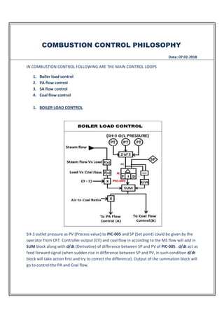
- 1. COMBUSTION CONTROL PHILOSOPHY Date: 07.02.2018 IN COMBUSTION CONTROL FOLLOWING ARE THE MAIN CONTROL LOOPS 1. Boiler load control 2. PA flow control 3. SA flow control 4. Coal flow control 1. BOILER LOAD CONTROL SH-3 outlet pressure as PV (Process value) to PIC-005 and SP (Set point) could be given by the operator from CRT. Controller output (CV) and coal flow in according to the MS flow will add in SUM block along with d/dt (Derivative) of difference between SP and PV of PIC-005. d/dt act as feed forward signal (when sudden rise in difference between SP and PV, in such condition d/dt block will take action first and try to correct the difference). Output of the summation block will go to control the PA and Coal flow.
- 2. 2. PA FLOW CONTROL LOOP Input SP to FIC-004A will come from comparator, here value between ‘A’ and multiplication of total coal flow with air to fuel ratio will be compared (greater than comparator is specially used to pass the air flow when steam flow increase or SH-3 outlet pressure decrease) PV to controller will come from the multiplication of total air flow and oxygen trimming. AIC-001 PV is actual flue gas oxygen reading and SP is given by operator from CRT. AIC-001 PID action is direct type controller (it means that if PV increase CV will increase and vice versa.) FIC-004A action = reverse, when Oxygen % decrease (PV of AIC-001) CV of AIC-001 will decrease and hence PV to FIC-004A will decrease. Hence indirectly we could say that, if oxygen in flue gas decrease this will increase FIC-004A output. FIC -004A output (CV) is SP for FIC-004; PV will come from actual PA flow. FIC-004 is reverse acting type controller.
- 3. 3. SA FLOW CONTROL After the oxygen trimming addition in logic, it is distributed for PA and SA flow control. C is the SA flow control from PA flow control sheet. SP to FIC-005 will come from first multiplication block, in this block input from PA to SA ratio and input from C is multiplied; it helps to maintain certain difference between SA and PA flow. After that greater than minimum and less than maximum block adder and this signal will go to FIC-005 as a SP and PV will come from actual SA flow. FIC-005 is reverse type controller. Bias will be given by operator from CRT.
- 4. 4. COAL FLOW CONTROL B is coal flow control from boiler load control, it will be the input to comparator and second input to comparator is multiplication of fuel to air ratio with total air flow and comparator will pass only less value to the next stage, then after greater than and less than block signal will go to FIC-001 as SP, PV will be come from DCF speed and constant multiplier block. Less than comparator block used to first pass the actual fuel flow (Total air flow x fuel air ratio). Because when boiler load control output increase (MS flow increase or SH-3 outlet pressure decrease), the value of B will go high, Actual air flow will increase slowly and according to this increasing rate fuel flow set point will also increase, this will helps to maintain bed temperature and proper combustion.