1. 1 / 5
Title: Isothermal flash Date: 8th June 2014
By: CangTo CHEAH
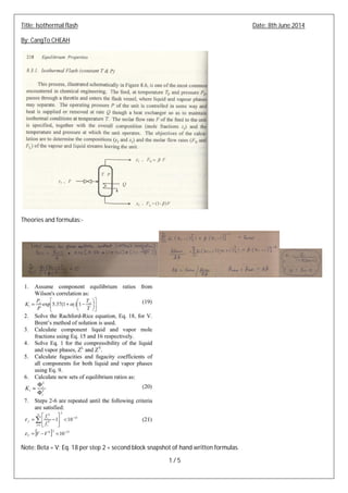
Theories and formulas:-
Note: Beta = V; Eq. 18 per step 2 = second block snapshot of hand written formulas.
2. 2 / 5
Target check case: PengShan LNG Project - Final Technical Package Rev. 2, 20-May-2014 (from APCI).
Stream number: 205 (LP stage mixed refrigerant compressor discharge)
Gas composition (mole %) for stream 205 (APCI's data):-
Phase map (per PRNAT EoS) for stream 205:-
Stream 205 is well within the vapor region; proceed to stream 206.
3. 3 / 5
Check stream 206 (downstream of cooler E-1301), P = 16.11 barA and T = 61.91 deg. C:-
Stream 206 is in the full vapor region, i.e. no liquid fraction is expected.
Check stream 207 (downstream of cooler E-1302), P = 15.91 barA and T = 37 deg. C:-
According to the phase map, stream 207 is within the vapor / liquid region. Mole fraction of gas composition within
vapor and liquid phases will be evaluated accordingly:-
PRNAT: APCI's data (vapor / liquid):
4. 4 / 5
Beta (vapor/[vapor + liquid]), calculated per PRNAT EoS = 0.87553
Given total mole flow = 8664.31 kmol/hr (per APCI's requirement), vapor and liquid mole flows are calculated as
follows:-
a) Vapor mole flow = PRNAT --> 7586 kmol/hr............................APCI --> 7527 kmol/hr
b) Liquid mole flow = PRNAT --> 1078 kmol/hr............................APCI --> 1137 kmol/hr
Stream 210 (HP stage mixed refrigerant compressor discharge flange; upstream of HP stage discharge cooler E-1303)
where P = 46 barA and T = 108.19 deg. C:-
Per above phase map, no liquid fraction is expected for stream 210.
Proceed to stream 212 (in between cooler E-1303 and E-1304), P = 45.8 barA and T = 70.73 deg. C:-
Stream 212 is within full vapor region, proceed further to stream 214 (downstream of cooler E-1304) where P =
45.40 barA and T = 37 deg. C:-
5. 5 / 5
According to the phase map, stream 214 is within the vapor / liquid region. Mole fraction of gas composition within
vapor and liquid phases will be evaluated:-
PRNAT: APCI's data (vapor / liquid):
Beta (vapor/[vapor + liquid]), calculated per PRNAT EoS = 0.83696
Given total mole flow = 7530.33 kmol/hr (per APCI's requirement), vapor and liquid mole flows are calculated as
follows:-
a) Vapor mole flow = PRNAT --> 6303 kmol/hr............................APCI --> 6151 kmol/hr
b) Liquid mole flow = PRNAT --> 1228 kmol/hr............................APCI --> 1380 kmol/hr
Conclusion:-
Theories and algorithms presented on page one perform well for evaluating isothermal flash problem using Peng-
Robinson-Nishiumi-Arai-Takeuchi equation of state; Isothermal flash is one of the most important and basic
ingredient in order to understand and appreciate the design of liquefaction system for LNG plant (as heat exchange
between mixed refrigerant gas and natural gas relies on the enthalpy balance of liquid & vapor phases of mixed
refrigerant with natural gas; calculation of enthalpy for liquid & vapor mixed refrigerant requires the knowledge of
gas compositions in each phases). Similar algorithms will be developed and implemented for high complexity
equations of state (e.g. BWRSNS and / or LKP) to check if the accuracies (in term of liquid & vapor distribution and
gas compositions within each phases) can be improved.