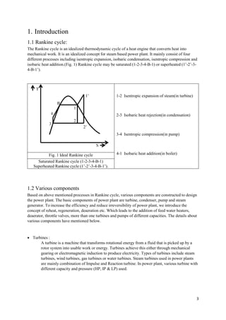
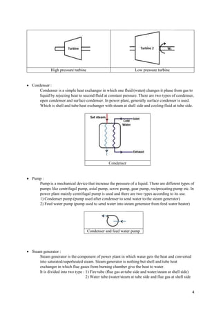
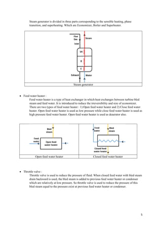
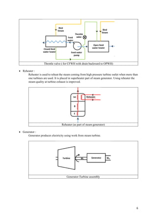
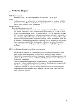
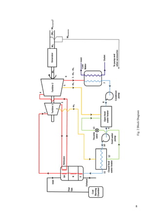
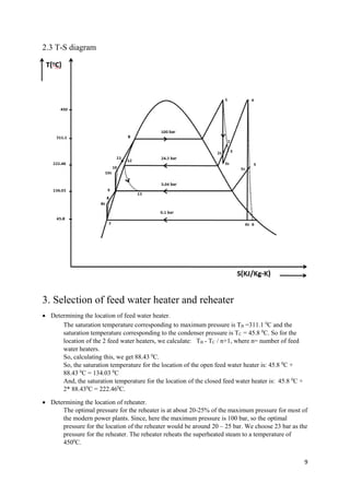
SlideShare a Scribd company logo
1 of 14
Download to read offline
1
Design of power plant based
on superheated Rankine cycle
Submitted by
Vaghela Nirav (UG201312035)
Leeladhar Sharma (M16ME008)
Himanshu Agrawal (UG201312013)
Dileep Kumar (M16ME009)
Rohit Singh (UG201312031)
Shubhendu Prashant Singh (M15ME012)
Under the guidance of
Dr. Laltu Chandra
Department of Mechanical Engineering
Indian Institute of Technology, Jodhpur
2
Contents
1.Introduction 3
1.1. Rankine cycle 3
1.2. Components 3
2. Proposed Design 7
2.1. Problem statement 7
2.2. Block Diagram 7
2.3. T-S Curve 9
3. Selection of FWH and Reheater 9
4. Parametric calculations 10
5. Performance characteristics 11
6. Turbine and pump selection 13
7. Future work 14
8. References 14
3
1. Introduction
1.1 Rankine cycle:
The Rankine cycle is an idealized thermodynamic cycle of a heat engine that converts heat into
mechanical work. It is an idealized concept for steam based power plant. It mainly consist of four
different processes including isentropic expansion, isobaric condensation, isentropic compression and
isobaric heat addition.(Fig. 1) Rankine cycle may be saturated (1-2-3-4-B-1) or superheated (1’-2’-3-
4-B-1’).
1-2 Isentropic expansion of steam(in turbine)
2-3 Isobaric heat rejection(in condensation)
3-4 Isentropic compression(in pump)
4-1 Isobaric heat addition(in boiler)Fig. 1 Ideal Rankine cycle
Saturated Rankine cycle (1-2-3-4-B-1)
Superheated Rankine cycle (1’-2’-3-4-B-1’).
1.2 Various components
Based on above mentioned processes in Rankine cycle, various components are constructed to design
the power plant. The basic components of power plant are turbine, condenser, pump and steam
generator. To increase the efficiency and reduce irreversibility of power plant, we introduce the
concept of reheat, regeneration, deaeration etc. Which leads to the addition of feed water heaters,
deaerator, throttle valves, more than one turbines and pumps of different capacities. The details about
various components have mentioned below.
 Turbines :
A turbine is a machine that transforms rotational energy from a fluid that is picked up by a
rotor system into usable work or energy. Turbines achieve this either through mechanical
gearing or electromagnetic induction to produce electricity. Types of turbines include steam
turbines, wind turbines, gas turbines or water turbines. Steam turbines used in power plants
are mainly combination of Impulse and Reaction turbine. In power plant, various turbine with
different capacity and pressure (HP, IP & LP) used.
4
 Condenser :
Condenser is a simple heat exchanger in which one fluid (water) changes it phase from gas to
liquid by rejecting heat to second fluid at constant pressure. There are two types of condenser,
open condenser and surface condenser. In power plant, generally surface condenser is used.
Which is shell and tube heat exchanger with steam at shell side and cooling fluid at tube side.
Condenser
 Pump :
Pump is a mechanical device that increase the pressure of a liquid. There are different types of
pumps like centrifugal pump, axial pump, screw pump, gear pump, reciprocating pump etc. In
power plant mainly centrifugal pump is used and there are two types according to its use.
1) Condenser pump (pump used after condenser to send water to the steam generator)
2) Feed water pump (pump used to send water into steam generator from feed water heater)
Condenser and feed water pump
 Steam generator :
Steam generator is the component of power plant in which water gets the heat and converted
into saturated/superheated steam. Steam generator is nothing but shell and tube heat
exchanger in which flue gases from burning chamber give the heat to water.
It is divided into two type : 1) Fire tube (flue gas at tube side and water/steam at shell side)
2) Water tube (water/steam at tube side and flue gas at shell side
High pressure turbine Low pressure turbine
Sat steam
5
Steam generator is divided in three parts corresponding to the sensible heating, phase
transition, and superheating. Which are Economizer, Boiler and Superheater.
Steam generator
 Feed water heater :
Feed water heater is a type of heat exchanger in which heat exchanges between turbine bled
steam and feed water. It is introduced to reduce the irreversibility and size of economizer.
There are two types of feed water heater : 1) Open feed water heater and 2) Close feed water
heater. Open feed water heater is used as low pressure while close feed water heater is used as
high pressure feed water heater. Open feed water heater is used as deaerator also.
Open feed water heater Closed feed water heater
 Throttle valve :
Throttle valve is used to reduce the pressure of fluid. When closed feed water with bled steam
drain backward is used, the bled steam is added to previous feed water heater or condenser
which are relatively at low pressure. So throttle valve is used to reduce the pressure of this
bled steam equal to the pressure exist at previous feed water heater or condenser.
6
Throttle valve ( for CFWH with drain backward to OPWH)
 Reheater :
Reheater is used to reheat the steam coming from high pressure turbine outlet when more than
one turbines are used. It is placed in superheater part of steam generator. Using reheater the
steam quality at turbine exhaust is improved.
Reheater (as part of steam generator)
 Generator :
Generator produces electricity using work from steam turbine.
Generator-Turbine assembly
7
2. Proposed design :
2.1 Problem statement :
We need to design a 1MW Power plant based on superheated Rankine cycle.
Given :
The inlet pressure to the turbine is 100 bar and the inlet pressure to the condenser is 0.1 bar.
The system contains: 2 feed water heaters: one open feed water heater containing deaerator
and one closed feed water heater, one reheater.
Proposed Design :
The proposed system comprises of:
A steam generator in which there are 3 sections namely economizer, boiler and superheater, a
high pressure turbine which works suitably between a pressure range of 20 – 100 bar, a low
pressure turbine which works suitably for pressure range of .1 – 20 bar, condenser, one open
feed water heater containing deaerator and one closed feed water heater and a throttle valve, a
feed water pump and a condensate pump. Also the system contains a generator whose shaft is
attached to the shaft of the turbines to generate electricity. Some of the generated power from
the generator is supplied to pump and other accessories. The coal is burnt in the coal burning
chamber and the produced hot flue gases are taken to the steam generator where the heat
energy is transferred from the flue gases to the water, the secondary fluid through a heat
exchanger.
2.2 The block diagram for the proposed design is as: (next page)
Here the red line represents the water after it is passed through the steam generator and it
passes through high pressure turbine to reheater to low pressure turbine to condenser.
The yellow line represents the bled steam where the one taken from the high pressure turbine
is fed to the closed feed water heater and the one bled from the low pressure turbine is fed to
the open feed water heater.
The green line represents the bled steam starting from point 12 and passing through the
throttle valve to the open feed water heater where at point 12 the bled steam is present in the
state after exchanging heat in the closed feed water heater.
The blue line represents the feed water starting after the condenser and going through the
condensate pump, open feed water heater, deaerator, feed water pump, closed feed water
heater to the steam generator.
8
Fig.2BlockDiagram
9
2.3 T-S diagram
3. Selection of feed water heater and reheater
 Determining the location of feed water heater.
The saturation temperature corresponding to maximum pressure is TB =311.1 0
C and the
saturation temperature corresponding to the condenser pressure is TC = 45.8 0
C. So for the
location of the 2 feed water heaters, we calculate: TB - TC / n+1, where n= number of feed
water heaters.
So, calculating this, we get 88.43 0
C.
So, the saturation temperature for the location of the open feed water heater is: 45.8 0
C +
88.43 0
C = 134.03 0
C
And, the saturation temperature for the location of the closed feed water heater is: 45.8 0
C +
2* 88.430
C = 222.460
C.
 Determining the location of reheater.
The optimal pressure for the reheater is at about 20-25% of the maximum pressure for most of
the modern power plants. Since, here the maximum pressure is 100 bar, so the optimal
pressure for the location of the reheater would be around 20 – 25 bar. We choose 23 bar as the
pressure for the reheater. The reheater reheats the superheated steam to a temperature of
4500
C.
10
4. Parametric calculations
Evaluation of enthalpies and mass flow rates.
Point-1:
Pb = P1 = 100 bar, Tsat = 311.1 o
C, T1 = 450 o
C
h1 = 3240.9 kJ/kg, s1 = 6.419 kJ/kg-K (From Steam Table)
Point-2:
P2 = 24.3 bar, s2s = 6.419 kJ/kg-K,
h2s = 2876.9 kJ/kg, T2s = 247.4 o
C , (From Steam Table)
ȠT1 = 0.60 = (h1 – h2) / (h1 – h2s)
h2 = 3022.5 kJ/kg-K
T2 = 303.53 o
C, (From Steam Table)
Point-3:
P3 = 23 bar, s3s = 6.419 kJ/kg-K
sg = 6.289 kJ/kg-K (< s3s) So condition of point 3s is superheated
h3s = 2841.24 kJ/kg, T3s = 226.8 K (From Steam Table)
ȠT1 = 0.60 = (h1 – h3) / (h1 – h3s)
h3 = 3001.10 kJ/kg
T3 = 272.32 o
C (From Steam Table)
Point-4:
P4 = P3 = 23 bar, T4 = 450 o
C
h4 = 3353.50 kJ/kg, s4 = 7.216 kJ/kg-K (From Steam Table)
Point-5:
P5 = 3.045 bar, s5s = 7.216 kJ/kg-K
sg = 6.972 kJ/kg-K (< s5s) So condition of point 3s is superheated
h5s = 2854.26 kJ/kg, T5s = 194.42 o
C (From Steam Table)
ȠT2 = 0.75 = (h4 – h5) / (h4 – h5s)
h5 = 2979.07 kJ/kg
T5 = 206.64 o
C (From Steam Table)
Point-6:
P6 = 0.1 bar, s6s = 7.216 kJ/kg-K,
sf = 0.649 kJ/kg-K, sfg = 7.501 kJ/kg-K (From Steam Table)
s6s = sf + x*sfg
x = .8754
hf = 191.8 kJ/kg, hfg = 2392.8 kJ/kg (From Steam Table)
h6s = hf + x*hfg = 2286.6 kJ/kg
ȠT2 = 0.75 = (h4 – h6) / (h4 – h6s)
h6 = 2550.32 kJ/kg
Point-7:
P7 = 0.1 bar, T7 = 45.8 K
h7 = hf = 191.80 kJ/kg, vf7 = 0.00101 m3
/kg (From Steam Table)
Point-8:
P8 = 3.045 bar,
h8s = h7 + vf7*(P8s – P7) = 192.09 kJ/kg
Ƞp1 = 0.75 = (h8s – h7) / (h8 – h7)
h8 = 192.19 kJ/kg
Point-9:
P9 = 3.045 bar, T9 = Tsat. = 134.03 o
C
h9 = hf @ 3.045 bar= 564.00 kJ/kg, vf9 = 0.0010735 m3
/kg (From Steam Table)
11
Point-10:
P10 = 100 bar,
h10s = h9 + vf9 * (P10s – P9) = 574.4 kJ/kg
Ƞp2 = 0.80 = (h10s – h9) / (h10 – h9)
h10 = 577.00 kJ/kg
Point-11:
P11 = 100 bar
T12 = Tsat.@ 24.3 bar = 222.46 o
C
Assume TTD = -3 0
C
T11 = T12 + TTD = 225.46 o
C
h11 = 969.20 kJ/kg (From Steam Table)
Point-12:
P12 = 24.3 bar
h12 = hf @ 24.3 bar = 955.10 kJ/kg (From Steam Table)
Point-13:
P13 = 3.04 bar
h13 = h12 = 955.10 kJ/kg (because, process 12-13 is isenthalpic)
Energy Balance: m2, h2
Closed feed water heater: 1, h11 1, h10
m2h2 + h10 = h11 + m2h12 CFWH
m2 = 0.19 kg/Sec. m2, h12
Open feed water heater: m2, h13 m5, h5
m2h13 + m5h5 + (1- m2- m5)*h8 = h9
m5 = 0.11 kg/Sec 1, h9 OFWH
(1-m2-m5), h8
5. Performance characteristics :
Turbine work output is given by (WT) = (h1- h2) + (1-ṁ2)*(h2– h3) + (1 - ṁ2)*(h4–h5) +
(1 - ṁ2 - ṁ5)*(h5–h6)
WT = (3240.90 – 3022.50) + ( 0.81) * (3022.50 – 3001.10) + (0.81)
* (3353.50 – 2979.07) + (0.70)*(2979.07 – 2550.32) kW
WT = 981.56 kW
Condensate Pump work input (Wcondensate pump ) = (1 - ṁ2 - ṁ5)* (h8- h7)
Wcondensate pump = (0.70) * (192.19 – 191.80) kw
Wcondensate pump = 0.273 kW
Feed water pump work input (Wfeed water pump) = 1* (h10- h9)
Wfeed water pump = 1* (577 - 564) kw
Wfeed water pump = 13 kW
Total pump work input (WP ) = Wcondensate pump+ Wfeed water pump
12
Wp = 13kW + 0.273 kW
Wp = 13.273kW
Net work done ( Wnet) = WT – Wp
Wnet = (981.56 – 13.273 ) kW
Wnet = 968.28 kW
Heat input is given by (Qin ) = (h1- h11) + (1 - ṁ2)*(h4 – h3)
Qin = (3240.90 – 969.20) + (0.81 )*(3022.50 – 3001.10) kW
Qin = 2557.14 kW
Heat rejected in condenser is (Qrejected ) = (1 - ṁ2 - ṁ5) * (h6 – h7)
Qrejected = (0.70) * (2550.32 – 191.80) kW
Qrejected = 1650.96 kW
Efficiency of cycle (ηthermal) = Wnet /Qin
ηthermal = 968.28 / 2557.14
ηthermal = 0.3786
Since for unit (1kg/s) mass flow rate we get energy output of 968.28 kJ
So for 1000 kJ energy output mass flow rate (ṁ) will be = 1*1000 / 968.28 = 1.033 kg/s
Hence mass flow rate of working fluid is 1.033 kg/s
And also heat input required corresponding to 1MW work output
Qin’=2557.14*1000/968.28=2640.91kW
Turbine work output cooresponding to 1.033 kg/s mass flow rate (WT’ ) = 1013.95 kW
Heat given to steam generator(QSG) = heat input required (Qin’ ) / steam generator efficiency
Assuming steam generator efficiency ηSG to be 0.8
QSG = 2640.91 / 0.8 = 3301.14kW = 3.301 MW
Fuel (coal) consumption rate (ṁcoal) = heat input to steam generator QSG
Calorific value of coal (CV)
Calorific value of coal is 27.26 MW/kg
ṁcoal = QSG / CV
ṁcoal = 3.30114 / 27.26 = 0.121kg/s = 436.05kg/hr
Net cycle heat rate is given by (HRnet cycle) =
steam generator efficiency * heat given to steam generator
Net work done
HRnet cycle = 0.8 *3301.14 / 1000
HRnet cycle = 2.64 = 9509.49 KJ/KWH
Assuming generator efficiency to be (nG) 0.94
Work output produced by generator (WG) = 0.94*1013.95 = 953.114 kW = 0.953MW
Net station Heat Rate (HRnet station)= _________heat given to steam generator_______________
Generator work output – work required in accessories (WA)
13
Assuming work required in other accessories to be 5% of generator work output.
Hence WA = 0.05*0.94 = 0.047 MW
HRnet station = QSG / WG - WA
HRnet station = 3.301/0.953-0.047 = 3.6435 = 13128.10 kJ/kWH
Gross cycle Heat Rate (HRgross cycle ) = ηSG * QSG / WT’
HRgross cycle = 0.8 * 3.301 /1.013 = 2.607 = 9378.6 kJ/kWH
Gross station Heat Rate (HRgross station) = heat input to steat generator (QSG)
Generator work output(WG)
HRgross station = 3.301/0.953 =3.4637 = 12471.63 kJ/kWH
6. Turbine and pump selection :
For turbine :
Company : Seimens
SST-060 steam turbine series
Power output up to 6 MW
Speed According to driven machine
Inlet steam pressure up to 131 bar (a)
Inlet steam temperature
Dry saturated steam up to
530°C
SST-100 steam turbine series
Power output up to 8.5 MW
Inlet steam pressure up to 65 bar (a)
Inlet steam temperature Dry saturated steam up to 480°C
Speed According to driven machine
14
For pumps :
1. HDX-TT (BB2) Radially Split, Power Recovery Turbine
Operating Parameters:
• Flow up to 4100 m3 /h (18 000 gpm)
• Head up to 760 m (2500 ft.)
• Pressure up to 100 bar (1450 psi)
• Temperature up to 450°C (842°F)
2. Kirloskar Pressure Booster Pump
CPBS- 84424H (1.5HP) 24L Tank
Operating Parameters:
• Power Rating : 1.5 hp
• Power Rating : 1.1 KW
• Flow rate : 80 LPM
• Pressure : 3.7 bar
7. Future work :
Basic power plant design and operating parameters are completed. Further, design of condenser will
be done by iteration using Kern’s method.
8. References :
www.turbinesinfo.com/steam-turbine-efficiency/
www.energy.siemens.com/hq/en/fossil-power-generation/steam-turbines/
Steam tables for steam
Power plant technology - MM.EI WAKIL
Power plant engineering - PK NAG

More Related Content

What's hot

Classification of boilers
Classification of boilersClassification of boilers
Classification of boilersPalanivel rajan
 
Properties of steam
Properties of steamProperties of steam
Properties of steamJitin Pillai
 
Vapour compression refrigeration system
Vapour compression refrigeration systemVapour compression refrigeration system
Vapour compression refrigeration systemnaphis ahamad
 
Basics of Vapor Compression.ppt
Basics of Vapor Compression.pptBasics of Vapor Compression.ppt
Basics of Vapor Compression.pptSyedZayanAli1
 
Ppt of properties of steam
Ppt of properties of steamPpt of properties of steam
Ppt of properties of steamKaushal Mehta
 
Energy, economic and environmental issues of power plants
Energy, economic and environmental issues of power plantsEnergy, economic and environmental issues of power plants
Energy, economic and environmental issues of power plantsBalamurugan Subburaj
 
Evaluation of a Boiler performance
Evaluation of a Boiler performanceEvaluation of a Boiler performance
Evaluation of a Boiler performanceHashim Hasnain Hadi
 
Waste heat recovery
Waste heat recoveryWaste heat recovery
Waste heat recoveryAneel Ahmad
 
Thermodynamic Chapter 5 Air Standard Cycle
Thermodynamic Chapter 5 Air Standard CycleThermodynamic Chapter 5 Air Standard Cycle
Thermodynamic Chapter 5 Air Standard CycleMuhammad Surahman
 
Multi pressure system in VCRS
Multi pressure system in VCRSMulti pressure system in VCRS
Multi pressure system in VCRSSuyog_Kadam
 
Combined Cycle Power Plant
Combined Cycle Power PlantCombined Cycle Power Plant
Combined Cycle Power PlantMd. Rimon Mia
 
STEAM NOZZLE AND STEAM TURBINE
STEAM NOZZLE AND STEAM TURBINESTEAM NOZZLE AND STEAM TURBINE
STEAM NOZZLE AND STEAM TURBINEDHAMMADIP KAMBLE
 
Air refrigerationsystem
Air refrigerationsystemAir refrigerationsystem
Air refrigerationsystemnaphis ahamad
 
gas turbine power plant
gas turbine power plantgas turbine power plant
gas turbine power plantDr. Ramesh B
 
Testing and performance of IC engine
Testing and performance of IC engineTesting and performance of IC engine
Testing and performance of IC engineMustafa Bzu
 
Psychrometry (air conditioning processes)
Psychrometry (air conditioning processes)Psychrometry (air conditioning processes)
Psychrometry (air conditioning processes)Yuri Melliza
 
Actual cycles of IC engines
Actual cycles of IC enginesActual cycles of IC engines
Actual cycles of IC enginesSoumith V
 

What's hot (20)

Classification of boilers
Classification of boilersClassification of boilers
Classification of boilers
 
Properties of steam
Properties of steamProperties of steam
Properties of steam
 
Vapour compression refrigeration system
Vapour compression refrigeration systemVapour compression refrigeration system
Vapour compression refrigeration system
 
Detonation
DetonationDetonation
Detonation
 
Basics of Vapor Compression.ppt
Basics of Vapor Compression.pptBasics of Vapor Compression.ppt
Basics of Vapor Compression.ppt
 
Ppt of properties of steam
Ppt of properties of steamPpt of properties of steam
Ppt of properties of steam
 
Energy, economic and environmental issues of power plants
Energy, economic and environmental issues of power plantsEnergy, economic and environmental issues of power plants
Energy, economic and environmental issues of power plants
 
Evaluation of a Boiler performance
Evaluation of a Boiler performanceEvaluation of a Boiler performance
Evaluation of a Boiler performance
 
Waste heat recovery
Waste heat recoveryWaste heat recovery
Waste heat recovery
 
Thermodynamic Chapter 5 Air Standard Cycle
Thermodynamic Chapter 5 Air Standard CycleThermodynamic Chapter 5 Air Standard Cycle
Thermodynamic Chapter 5 Air Standard Cycle
 
Multi pressure system in VCRS
Multi pressure system in VCRSMulti pressure system in VCRS
Multi pressure system in VCRS
 
Combined Cycle Power Plant
Combined Cycle Power PlantCombined Cycle Power Plant
Combined Cycle Power Plant
 
STEAM NOZZLE AND STEAM TURBINE
STEAM NOZZLE AND STEAM TURBINESTEAM NOZZLE AND STEAM TURBINE
STEAM NOZZLE AND STEAM TURBINE
 
Centrifugal compressor
Centrifugal compressor Centrifugal compressor
Centrifugal compressor
 
Air refrigerationsystem
Air refrigerationsystemAir refrigerationsystem
Air refrigerationsystem
 
gas turbine power plant
gas turbine power plantgas turbine power plant
gas turbine power plant
 
Testing and performance of IC engine
Testing and performance of IC engineTesting and performance of IC engine
Testing and performance of IC engine
 
Psychrometry (air conditioning processes)
Psychrometry (air conditioning processes)Psychrometry (air conditioning processes)
Psychrometry (air conditioning processes)
 
Evaporators
EvaporatorsEvaporators
Evaporators
 
Actual cycles of IC engines
Actual cycles of IC enginesActual cycles of IC engines
Actual cycles of IC engines
 

Viewers also liked

MET 401 Chapter 2 improvement_to_rankine_cycle
MET 401 Chapter 2 improvement_to_rankine_cycleMET 401 Chapter 2 improvement_to_rankine_cycle
MET 401 Chapter 2 improvement_to_rankine_cycleIbrahim AboKhalil
 
Rankine cycle power plant
Rankine cycle   power plantRankine cycle   power plant
Rankine cycle power plantDeeSolar
 
Rankinecycle 120509124313-phpapp02 (3)
Rankinecycle 120509124313-phpapp02 (3)Rankinecycle 120509124313-phpapp02 (3)
Rankinecycle 120509124313-phpapp02 (3)yamini champaneri
 

Viewers also liked (6)

MET 401 Chapter 2 improvement_to_rankine_cycle
MET 401 Chapter 2 improvement_to_rankine_cycleMET 401 Chapter 2 improvement_to_rankine_cycle
MET 401 Chapter 2 improvement_to_rankine_cycle
 
Rankine cycle power plant
Rankine cycle   power plantRankine cycle   power plant
Rankine cycle power plant
 
Cooling water (CW) system
Cooling water (CW) system Cooling water (CW) system
Cooling water (CW) system
 
Rankinecycle 120509124313-phpapp02 (3)
Rankinecycle 120509124313-phpapp02 (3)Rankinecycle 120509124313-phpapp02 (3)
Rankinecycle 120509124313-phpapp02 (3)
 
rankine cycle
rankine cyclerankine cycle
rankine cycle
 
Rankine cycle
Rankine cycleRankine cycle
Rankine cycle
 

Similar to Power plant based on Rankine cycle

Regenerative feed water heating cycle
Regenerative feed water heating cycleRegenerative feed water heating cycle
Regenerative feed water heating cycle431996
 
Industrial training at NTPC Shaktinagar
Industrial training at NTPC ShaktinagarIndustrial training at NTPC Shaktinagar
Industrial training at NTPC ShaktinagarRishikesh .
 
SUMMER INTERNSHIP(INDUSTRAIL REPORT) ON THERMAL POWER PLANT
SUMMER INTERNSHIP(INDUSTRAIL REPORT) ON THERMAL POWER PLANT SUMMER INTERNSHIP(INDUSTRAIL REPORT) ON THERMAL POWER PLANT
SUMMER INTERNSHIP(INDUSTRAIL REPORT) ON THERMAL POWER PLANT Amit Gupta
 
NTPC ,sipat voccational training
NTPC ,sipat voccational trainingNTPC ,sipat voccational training
NTPC ,sipat voccational trainingbhumit1
 
Thermal Analysis of Steam Turbine Power Plants
Thermal Analysis of Steam Turbine Power PlantsThermal Analysis of Steam Turbine Power Plants
Thermal Analysis of Steam Turbine Power PlantsIOSR Journals
 
Thermal power plant
Thermal power plantThermal power plant
Thermal power plantfoxycrow
 
Sandeep verma ppt on kstps
Sandeep verma ppt on kstps   Sandeep verma ppt on kstps
Sandeep verma ppt on kstps sandeep244266
 
Coal Base Thermal Power Plant
Coal Base Thermal Power PlantCoal Base Thermal Power Plant
Coal Base Thermal Power PlantPankaj Mohan
 
01 regenerative feed heating
01 regenerative feed heating01 regenerative feed heating
01 regenerative feed heatingAnil Palamwar
 
steam turbine[1] (3).pptxshshshhhshshshh
steam turbine[1] (3).pptxshshshhhshshshhsteam turbine[1] (3).pptxshshshhhshshshh
steam turbine[1] (3).pptxshshshhhshshshhAzizAlabad
 
Improvement of rankine efficinecy of steam power plants
Improvement of rankine efficinecy of steam power plantsImprovement of rankine efficinecy of steam power plants
Improvement of rankine efficinecy of steam power plantsDhilip Pugalenthi
 
Thermal power plant
Thermal power plantThermal power plant
Thermal power plantViren Patel
 

Similar to Power plant based on Rankine cycle (20)

Regenerative feed water heating cycle
Regenerative feed water heating cycleRegenerative feed water heating cycle
Regenerative feed water heating cycle
 
POWER PLANT.pdf
POWER PLANT.pdfPOWER PLANT.pdf
POWER PLANT.pdf
 
Industrial training at NTPC Shaktinagar
Industrial training at NTPC ShaktinagarIndustrial training at NTPC Shaktinagar
Industrial training at NTPC Shaktinagar
 
SUMMER INTERNSHIP(INDUSTRAIL REPORT) ON THERMAL POWER PLANT
SUMMER INTERNSHIP(INDUSTRAIL REPORT) ON THERMAL POWER PLANT SUMMER INTERNSHIP(INDUSTRAIL REPORT) ON THERMAL POWER PLANT
SUMMER INTERNSHIP(INDUSTRAIL REPORT) ON THERMAL POWER PLANT
 
NTPC ,sipat voccational training
NTPC ,sipat voccational trainingNTPC ,sipat voccational training
NTPC ,sipat voccational training
 
Thermal Analysis of Steam Turbine Power Plants
Thermal Analysis of Steam Turbine Power PlantsThermal Analysis of Steam Turbine Power Plants
Thermal Analysis of Steam Turbine Power Plants
 
N012229496
N012229496N012229496
N012229496
 
Thermal power plant
Thermal power plantThermal power plant
Thermal power plant
 
Sandeep verma ppt on kstps
Sandeep verma ppt on kstps   Sandeep verma ppt on kstps
Sandeep verma ppt on kstps
 
STEAM POWER PLANT
STEAM POWER PLANTSTEAM POWER PLANT
STEAM POWER PLANT
 
Power plant
Power plantPower plant
Power plant
 
Steam turbine
Steam turbineSteam turbine
Steam turbine
 
Power Systems-I.pdf
Power Systems-I.pdfPower Systems-I.pdf
Power Systems-I.pdf
 
Coal Base Thermal Power Plant
Coal Base Thermal Power PlantCoal Base Thermal Power Plant
Coal Base Thermal Power Plant
 
01 regenerative feed heating
01 regenerative feed heating01 regenerative feed heating
01 regenerative feed heating
 
steam turbine[1] (3).pptxshshshhhshshshh
steam turbine[1] (3).pptxshshshhhshshshhsteam turbine[1] (3).pptxshshshhhshshshh
steam turbine[1] (3).pptxshshshhhshshshh
 
Chapter 10 lecture
Chapter 10 lectureChapter 10 lecture
Chapter 10 lecture
 
Bandel training
Bandel trainingBandel training
Bandel training
 
Improvement of rankine efficinecy of steam power plants
Improvement of rankine efficinecy of steam power plantsImprovement of rankine efficinecy of steam power plants
Improvement of rankine efficinecy of steam power plants
 
Thermal power plant
Thermal power plantThermal power plant
Thermal power plant
 

Recently uploaded

main PPT.pptx of girls hostel security using rfid
main PPT.pptx of girls hostel security using rfidmain PPT.pptx of girls hostel security using rfid
main PPT.pptx of girls hostel security using rfidNikhilNagaraju
 
Work Experience-Dalton Park.pptxfvvvvvvv
Work Experience-Dalton Park.pptxfvvvvvvvWork Experience-Dalton Park.pptxfvvvvvvv
Work Experience-Dalton Park.pptxfvvvvvvvLewisJB
 
Introduction-To-Agricultural-Surveillance-Rover.pptx
Introduction-To-Agricultural-Surveillance-Rover.pptxIntroduction-To-Agricultural-Surveillance-Rover.pptx
Introduction-To-Agricultural-Surveillance-Rover.pptxk795866
 
Heart Disease Prediction using machine learning.pptx
Heart Disease Prediction using machine learning.pptxHeart Disease Prediction using machine learning.pptx
Heart Disease Prediction using machine learning.pptxPoojaBan
 
Biology for Computer Engineers Course Handout.pptx
Biology for Computer Engineers Course Handout.pptxBiology for Computer Engineers Course Handout.pptx
Biology for Computer Engineers Course Handout.pptxDeepakSakkari2
 
Architect Hassan Khalil Portfolio for 2024
Architect Hassan Khalil Portfolio for 2024Architect Hassan Khalil Portfolio for 2024
Architect Hassan Khalil Portfolio for 2024hassan khalil
 
Call Girls Delhi {Jodhpur} 9711199012 high profile service
Call Girls Delhi {Jodhpur} 9711199012 high profile serviceCall Girls Delhi {Jodhpur} 9711199012 high profile service
Call Girls Delhi {Jodhpur} 9711199012 high profile servicerehmti665
 
Application of Residue Theorem to evaluate real integrations.pptx
Application of Residue Theorem to evaluate real integrations.pptxApplication of Residue Theorem to evaluate real integrations.pptx
Application of Residue Theorem to evaluate real integrations.pptx959SahilShah
 
Gurgaon ✡️9711147426✨Call In girls Gurgaon Sector 51 escort service
Gurgaon ✡️9711147426✨Call In girls Gurgaon Sector 51 escort serviceGurgaon ✡️9711147426✨Call In girls Gurgaon Sector 51 escort service
Gurgaon ✡️9711147426✨Call In girls Gurgaon Sector 51 escort servicejennyeacort
 
DATA ANALYTICS PPT definition usage example
DATA ANALYTICS PPT definition usage exampleDATA ANALYTICS PPT definition usage example
DATA ANALYTICS PPT definition usage examplePragyanshuParadkar1
 
CCS355 Neural Networks & Deep Learning Unit 1 PDF notes with Question bank .pdf
CCS355 Neural Networks & Deep Learning Unit 1 PDF notes with Question bank .pdfCCS355 Neural Networks & Deep Learning Unit 1 PDF notes with Question bank .pdf
CCS355 Neural Networks & Deep Learning Unit 1 PDF notes with Question bank .pdfAsst.prof M.Gokilavani
 
Internship report on mechanical engineering
Internship report on mechanical engineeringInternship report on mechanical engineering
Internship report on mechanical engineeringmalavadedarshan25
 
Churning of Butter, Factors affecting .
Churning of Butter, Factors affecting  .Churning of Butter, Factors affecting  .
Churning of Butter, Factors affecting .Satyam Kumar
 
Concrete Mix Design - IS 10262-2019 - .pptx
Concrete Mix Design - IS 10262-2019 - .pptxConcrete Mix Design - IS 10262-2019 - .pptx
Concrete Mix Design - IS 10262-2019 - .pptxKartikeyaDwivedi3
 
Electronically Controlled suspensions system .pdf
Electronically Controlled suspensions system .pdfElectronically Controlled suspensions system .pdf
Electronically Controlled suspensions system .pdfme23b1001
 
HARMONY IN THE NATURE AND EXISTENCE - Unit-IV
HARMONY IN THE NATURE AND EXISTENCE - Unit-IVHARMONY IN THE NATURE AND EXISTENCE - Unit-IV
HARMONY IN THE NATURE AND EXISTENCE - Unit-IVRajaP95
 
CCS355 Neural Network & Deep Learning UNIT III notes and Question bank .pdf
CCS355 Neural Network & Deep Learning UNIT III notes and Question bank .pdfCCS355 Neural Network & Deep Learning UNIT III notes and Question bank .pdf
CCS355 Neural Network & Deep Learning UNIT III notes and Question bank .pdfAsst.prof M.Gokilavani
 

Recently uploaded (20)

Call Us -/9953056974- Call Girls In Vikaspuri-/- Delhi NCR
Call Us -/9953056974- Call Girls In Vikaspuri-/- Delhi NCRCall Us -/9953056974- Call Girls In Vikaspuri-/- Delhi NCR
Call Us -/9953056974- Call Girls In Vikaspuri-/- Delhi NCR
 
main PPT.pptx of girls hostel security using rfid
main PPT.pptx of girls hostel security using rfidmain PPT.pptx of girls hostel security using rfid
main PPT.pptx of girls hostel security using rfid
 
Work Experience-Dalton Park.pptxfvvvvvvv
Work Experience-Dalton Park.pptxfvvvvvvvWork Experience-Dalton Park.pptxfvvvvvvv
Work Experience-Dalton Park.pptxfvvvvvvv
 
Introduction-To-Agricultural-Surveillance-Rover.pptx
Introduction-To-Agricultural-Surveillance-Rover.pptxIntroduction-To-Agricultural-Surveillance-Rover.pptx
Introduction-To-Agricultural-Surveillance-Rover.pptx
 
Heart Disease Prediction using machine learning.pptx
Heart Disease Prediction using machine learning.pptxHeart Disease Prediction using machine learning.pptx
Heart Disease Prediction using machine learning.pptx
 
young call girls in Green Park🔝 9953056974 🔝 escort Service
young call girls in Green Park🔝 9953056974 🔝 escort Serviceyoung call girls in Green Park🔝 9953056974 🔝 escort Service
young call girls in Green Park🔝 9953056974 🔝 escort Service
 
Biology for Computer Engineers Course Handout.pptx
Biology for Computer Engineers Course Handout.pptxBiology for Computer Engineers Course Handout.pptx
Biology for Computer Engineers Course Handout.pptx
 
Architect Hassan Khalil Portfolio for 2024
Architect Hassan Khalil Portfolio for 2024Architect Hassan Khalil Portfolio for 2024
Architect Hassan Khalil Portfolio for 2024
 
Call Girls Delhi {Jodhpur} 9711199012 high profile service
Call Girls Delhi {Jodhpur} 9711199012 high profile serviceCall Girls Delhi {Jodhpur} 9711199012 high profile service
Call Girls Delhi {Jodhpur} 9711199012 high profile service
 
Application of Residue Theorem to evaluate real integrations.pptx
Application of Residue Theorem to evaluate real integrations.pptxApplication of Residue Theorem to evaluate real integrations.pptx
Application of Residue Theorem to evaluate real integrations.pptx
 
Gurgaon ✡️9711147426✨Call In girls Gurgaon Sector 51 escort service
Gurgaon ✡️9711147426✨Call In girls Gurgaon Sector 51 escort serviceGurgaon ✡️9711147426✨Call In girls Gurgaon Sector 51 escort service
Gurgaon ✡️9711147426✨Call In girls Gurgaon Sector 51 escort service
 
DATA ANALYTICS PPT definition usage example
DATA ANALYTICS PPT definition usage exampleDATA ANALYTICS PPT definition usage example
DATA ANALYTICS PPT definition usage example
 
CCS355 Neural Networks & Deep Learning Unit 1 PDF notes with Question bank .pdf
CCS355 Neural Networks & Deep Learning Unit 1 PDF notes with Question bank .pdfCCS355 Neural Networks & Deep Learning Unit 1 PDF notes with Question bank .pdf
CCS355 Neural Networks & Deep Learning Unit 1 PDF notes with Question bank .pdf
 
Internship report on mechanical engineering
Internship report on mechanical engineeringInternship report on mechanical engineering
Internship report on mechanical engineering
 
Churning of Butter, Factors affecting .
Churning of Butter, Factors affecting  .Churning of Butter, Factors affecting  .
Churning of Butter, Factors affecting .
 
Concrete Mix Design - IS 10262-2019 - .pptx
Concrete Mix Design - IS 10262-2019 - .pptxConcrete Mix Design - IS 10262-2019 - .pptx
Concrete Mix Design - IS 10262-2019 - .pptx
 
Electronically Controlled suspensions system .pdf
Electronically Controlled suspensions system .pdfElectronically Controlled suspensions system .pdf
Electronically Controlled suspensions system .pdf
 
young call girls in Rajiv Chowk🔝 9953056974 🔝 Delhi escort Service
young call girls in Rajiv Chowk🔝 9953056974 🔝 Delhi escort Serviceyoung call girls in Rajiv Chowk🔝 9953056974 🔝 Delhi escort Service
young call girls in Rajiv Chowk🔝 9953056974 🔝 Delhi escort Service
 
HARMONY IN THE NATURE AND EXISTENCE - Unit-IV
HARMONY IN THE NATURE AND EXISTENCE - Unit-IVHARMONY IN THE NATURE AND EXISTENCE - Unit-IV
HARMONY IN THE NATURE AND EXISTENCE - Unit-IV
 
CCS355 Neural Network & Deep Learning UNIT III notes and Question bank .pdf
CCS355 Neural Network & Deep Learning UNIT III notes and Question bank .pdfCCS355 Neural Network & Deep Learning UNIT III notes and Question bank .pdf
CCS355 Neural Network & Deep Learning UNIT III notes and Question bank .pdf
 

Power plant based on Rankine cycle

  • 1. 1 Design of power plant based on superheated Rankine cycle Submitted by Vaghela Nirav (UG201312035) Leeladhar Sharma (M16ME008) Himanshu Agrawal (UG201312013) Dileep Kumar (M16ME009) Rohit Singh (UG201312031) Shubhendu Prashant Singh (M15ME012) Under the guidance of Dr. Laltu Chandra Department of Mechanical Engineering Indian Institute of Technology, Jodhpur
  • 2. 2 Contents 1.Introduction 3 1.1. Rankine cycle 3 1.2. Components 3 2. Proposed Design 7 2.1. Problem statement 7 2.2. Block Diagram 7 2.3. T-S Curve 9 3. Selection of FWH and Reheater 9 4. Parametric calculations 10 5. Performance characteristics 11 6. Turbine and pump selection 13 7. Future work 14 8. References 14
  • 3. 3 1. Introduction 1.1 Rankine cycle: The Rankine cycle is an idealized thermodynamic cycle of a heat engine that converts heat into mechanical work. It is an idealized concept for steam based power plant. It mainly consist of four different processes including isentropic expansion, isobaric condensation, isentropic compression and isobaric heat addition.(Fig. 1) Rankine cycle may be saturated (1-2-3-4-B-1) or superheated (1’-2’-3- 4-B-1’). 1-2 Isentropic expansion of steam(in turbine) 2-3 Isobaric heat rejection(in condensation) 3-4 Isentropic compression(in pump) 4-1 Isobaric heat addition(in boiler)Fig. 1 Ideal Rankine cycle Saturated Rankine cycle (1-2-3-4-B-1) Superheated Rankine cycle (1’-2’-3-4-B-1’). 1.2 Various components Based on above mentioned processes in Rankine cycle, various components are constructed to design the power plant. The basic components of power plant are turbine, condenser, pump and steam generator. To increase the efficiency and reduce irreversibility of power plant, we introduce the concept of reheat, regeneration, deaeration etc. Which leads to the addition of feed water heaters, deaerator, throttle valves, more than one turbines and pumps of different capacities. The details about various components have mentioned below.  Turbines : A turbine is a machine that transforms rotational energy from a fluid that is picked up by a rotor system into usable work or energy. Turbines achieve this either through mechanical gearing or electromagnetic induction to produce electricity. Types of turbines include steam turbines, wind turbines, gas turbines or water turbines. Steam turbines used in power plants are mainly combination of Impulse and Reaction turbine. In power plant, various turbine with different capacity and pressure (HP, IP & LP) used.
  • 4. 4  Condenser : Condenser is a simple heat exchanger in which one fluid (water) changes it phase from gas to liquid by rejecting heat to second fluid at constant pressure. There are two types of condenser, open condenser and surface condenser. In power plant, generally surface condenser is used. Which is shell and tube heat exchanger with steam at shell side and cooling fluid at tube side. Condenser  Pump : Pump is a mechanical device that increase the pressure of a liquid. There are different types of pumps like centrifugal pump, axial pump, screw pump, gear pump, reciprocating pump etc. In power plant mainly centrifugal pump is used and there are two types according to its use. 1) Condenser pump (pump used after condenser to send water to the steam generator) 2) Feed water pump (pump used to send water into steam generator from feed water heater) Condenser and feed water pump  Steam generator : Steam generator is the component of power plant in which water gets the heat and converted into saturated/superheated steam. Steam generator is nothing but shell and tube heat exchanger in which flue gases from burning chamber give the heat to water. It is divided into two type : 1) Fire tube (flue gas at tube side and water/steam at shell side) 2) Water tube (water/steam at tube side and flue gas at shell side High pressure turbine Low pressure turbine Sat steam
  • 5. 5 Steam generator is divided in three parts corresponding to the sensible heating, phase transition, and superheating. Which are Economizer, Boiler and Superheater. Steam generator  Feed water heater : Feed water heater is a type of heat exchanger in which heat exchanges between turbine bled steam and feed water. It is introduced to reduce the irreversibility and size of economizer. There are two types of feed water heater : 1) Open feed water heater and 2) Close feed water heater. Open feed water heater is used as low pressure while close feed water heater is used as high pressure feed water heater. Open feed water heater is used as deaerator also. Open feed water heater Closed feed water heater  Throttle valve : Throttle valve is used to reduce the pressure of fluid. When closed feed water with bled steam drain backward is used, the bled steam is added to previous feed water heater or condenser which are relatively at low pressure. So throttle valve is used to reduce the pressure of this bled steam equal to the pressure exist at previous feed water heater or condenser.
  • 6. 6 Throttle valve ( for CFWH with drain backward to OPWH)  Reheater : Reheater is used to reheat the steam coming from high pressure turbine outlet when more than one turbines are used. It is placed in superheater part of steam generator. Using reheater the steam quality at turbine exhaust is improved. Reheater (as part of steam generator)  Generator : Generator produces electricity using work from steam turbine. Generator-Turbine assembly
  • 7. 7 2. Proposed design : 2.1 Problem statement : We need to design a 1MW Power plant based on superheated Rankine cycle. Given : The inlet pressure to the turbine is 100 bar and the inlet pressure to the condenser is 0.1 bar. The system contains: 2 feed water heaters: one open feed water heater containing deaerator and one closed feed water heater, one reheater. Proposed Design : The proposed system comprises of: A steam generator in which there are 3 sections namely economizer, boiler and superheater, a high pressure turbine which works suitably between a pressure range of 20 – 100 bar, a low pressure turbine which works suitably for pressure range of .1 – 20 bar, condenser, one open feed water heater containing deaerator and one closed feed water heater and a throttle valve, a feed water pump and a condensate pump. Also the system contains a generator whose shaft is attached to the shaft of the turbines to generate electricity. Some of the generated power from the generator is supplied to pump and other accessories. The coal is burnt in the coal burning chamber and the produced hot flue gases are taken to the steam generator where the heat energy is transferred from the flue gases to the water, the secondary fluid through a heat exchanger. 2.2 The block diagram for the proposed design is as: (next page) Here the red line represents the water after it is passed through the steam generator and it passes through high pressure turbine to reheater to low pressure turbine to condenser. The yellow line represents the bled steam where the one taken from the high pressure turbine is fed to the closed feed water heater and the one bled from the low pressure turbine is fed to the open feed water heater. The green line represents the bled steam starting from point 12 and passing through the throttle valve to the open feed water heater where at point 12 the bled steam is present in the state after exchanging heat in the closed feed water heater. The blue line represents the feed water starting after the condenser and going through the condensate pump, open feed water heater, deaerator, feed water pump, closed feed water heater to the steam generator.
  • 9. 9 2.3 T-S diagram 3. Selection of feed water heater and reheater  Determining the location of feed water heater. The saturation temperature corresponding to maximum pressure is TB =311.1 0 C and the saturation temperature corresponding to the condenser pressure is TC = 45.8 0 C. So for the location of the 2 feed water heaters, we calculate: TB - TC / n+1, where n= number of feed water heaters. So, calculating this, we get 88.43 0 C. So, the saturation temperature for the location of the open feed water heater is: 45.8 0 C + 88.43 0 C = 134.03 0 C And, the saturation temperature for the location of the closed feed water heater is: 45.8 0 C + 2* 88.430 C = 222.460 C.  Determining the location of reheater. The optimal pressure for the reheater is at about 20-25% of the maximum pressure for most of the modern power plants. Since, here the maximum pressure is 100 bar, so the optimal pressure for the location of the reheater would be around 20 – 25 bar. We choose 23 bar as the pressure for the reheater. The reheater reheats the superheated steam to a temperature of 4500 C.
  • 10. 10 4. Parametric calculations Evaluation of enthalpies and mass flow rates. Point-1: Pb = P1 = 100 bar, Tsat = 311.1 o C, T1 = 450 o C h1 = 3240.9 kJ/kg, s1 = 6.419 kJ/kg-K (From Steam Table) Point-2: P2 = 24.3 bar, s2s = 6.419 kJ/kg-K, h2s = 2876.9 kJ/kg, T2s = 247.4 o C , (From Steam Table) ȠT1 = 0.60 = (h1 – h2) / (h1 – h2s) h2 = 3022.5 kJ/kg-K T2 = 303.53 o C, (From Steam Table) Point-3: P3 = 23 bar, s3s = 6.419 kJ/kg-K sg = 6.289 kJ/kg-K (< s3s) So condition of point 3s is superheated h3s = 2841.24 kJ/kg, T3s = 226.8 K (From Steam Table) ȠT1 = 0.60 = (h1 – h3) / (h1 – h3s) h3 = 3001.10 kJ/kg T3 = 272.32 o C (From Steam Table) Point-4: P4 = P3 = 23 bar, T4 = 450 o C h4 = 3353.50 kJ/kg, s4 = 7.216 kJ/kg-K (From Steam Table) Point-5: P5 = 3.045 bar, s5s = 7.216 kJ/kg-K sg = 6.972 kJ/kg-K (< s5s) So condition of point 3s is superheated h5s = 2854.26 kJ/kg, T5s = 194.42 o C (From Steam Table) ȠT2 = 0.75 = (h4 – h5) / (h4 – h5s) h5 = 2979.07 kJ/kg T5 = 206.64 o C (From Steam Table) Point-6: P6 = 0.1 bar, s6s = 7.216 kJ/kg-K, sf = 0.649 kJ/kg-K, sfg = 7.501 kJ/kg-K (From Steam Table) s6s = sf + x*sfg x = .8754 hf = 191.8 kJ/kg, hfg = 2392.8 kJ/kg (From Steam Table) h6s = hf + x*hfg = 2286.6 kJ/kg ȠT2 = 0.75 = (h4 – h6) / (h4 – h6s) h6 = 2550.32 kJ/kg Point-7: P7 = 0.1 bar, T7 = 45.8 K h7 = hf = 191.80 kJ/kg, vf7 = 0.00101 m3 /kg (From Steam Table) Point-8: P8 = 3.045 bar, h8s = h7 + vf7*(P8s – P7) = 192.09 kJ/kg Ƞp1 = 0.75 = (h8s – h7) / (h8 – h7) h8 = 192.19 kJ/kg Point-9: P9 = 3.045 bar, T9 = Tsat. = 134.03 o C h9 = hf @ 3.045 bar= 564.00 kJ/kg, vf9 = 0.0010735 m3 /kg (From Steam Table)
  • 11. 11 Point-10: P10 = 100 bar, h10s = h9 + vf9 * (P10s – P9) = 574.4 kJ/kg Ƞp2 = 0.80 = (h10s – h9) / (h10 – h9) h10 = 577.00 kJ/kg Point-11: P11 = 100 bar T12 = Tsat.@ 24.3 bar = 222.46 o C Assume TTD = -3 0 C T11 = T12 + TTD = 225.46 o C h11 = 969.20 kJ/kg (From Steam Table) Point-12: P12 = 24.3 bar h12 = hf @ 24.3 bar = 955.10 kJ/kg (From Steam Table) Point-13: P13 = 3.04 bar h13 = h12 = 955.10 kJ/kg (because, process 12-13 is isenthalpic) Energy Balance: m2, h2 Closed feed water heater: 1, h11 1, h10 m2h2 + h10 = h11 + m2h12 CFWH m2 = 0.19 kg/Sec. m2, h12 Open feed water heater: m2, h13 m5, h5 m2h13 + m5h5 + (1- m2- m5)*h8 = h9 m5 = 0.11 kg/Sec 1, h9 OFWH (1-m2-m5), h8 5. Performance characteristics : Turbine work output is given by (WT) = (h1- h2) + (1-ṁ2)*(h2– h3) + (1 - ṁ2)*(h4–h5) + (1 - ṁ2 - ṁ5)*(h5–h6) WT = (3240.90 – 3022.50) + ( 0.81) * (3022.50 – 3001.10) + (0.81) * (3353.50 – 2979.07) + (0.70)*(2979.07 – 2550.32) kW WT = 981.56 kW Condensate Pump work input (Wcondensate pump ) = (1 - ṁ2 - ṁ5)* (h8- h7) Wcondensate pump = (0.70) * (192.19 – 191.80) kw Wcondensate pump = 0.273 kW Feed water pump work input (Wfeed water pump) = 1* (h10- h9) Wfeed water pump = 1* (577 - 564) kw Wfeed water pump = 13 kW Total pump work input (WP ) = Wcondensate pump+ Wfeed water pump
  • 12. 12 Wp = 13kW + 0.273 kW Wp = 13.273kW Net work done ( Wnet) = WT – Wp Wnet = (981.56 – 13.273 ) kW Wnet = 968.28 kW Heat input is given by (Qin ) = (h1- h11) + (1 - ṁ2)*(h4 – h3) Qin = (3240.90 – 969.20) + (0.81 )*(3022.50 – 3001.10) kW Qin = 2557.14 kW Heat rejected in condenser is (Qrejected ) = (1 - ṁ2 - ṁ5) * (h6 – h7) Qrejected = (0.70) * (2550.32 – 191.80) kW Qrejected = 1650.96 kW Efficiency of cycle (ηthermal) = Wnet /Qin ηthermal = 968.28 / 2557.14 ηthermal = 0.3786 Since for unit (1kg/s) mass flow rate we get energy output of 968.28 kJ So for 1000 kJ energy output mass flow rate (ṁ) will be = 1*1000 / 968.28 = 1.033 kg/s Hence mass flow rate of working fluid is 1.033 kg/s And also heat input required corresponding to 1MW work output Qin’=2557.14*1000/968.28=2640.91kW Turbine work output cooresponding to 1.033 kg/s mass flow rate (WT’ ) = 1013.95 kW Heat given to steam generator(QSG) = heat input required (Qin’ ) / steam generator efficiency Assuming steam generator efficiency ηSG to be 0.8 QSG = 2640.91 / 0.8 = 3301.14kW = 3.301 MW Fuel (coal) consumption rate (ṁcoal) = heat input to steam generator QSG Calorific value of coal (CV) Calorific value of coal is 27.26 MW/kg ṁcoal = QSG / CV ṁcoal = 3.30114 / 27.26 = 0.121kg/s = 436.05kg/hr Net cycle heat rate is given by (HRnet cycle) = steam generator efficiency * heat given to steam generator Net work done HRnet cycle = 0.8 *3301.14 / 1000 HRnet cycle = 2.64 = 9509.49 KJ/KWH Assuming generator efficiency to be (nG) 0.94 Work output produced by generator (WG) = 0.94*1013.95 = 953.114 kW = 0.953MW Net station Heat Rate (HRnet station)= _________heat given to steam generator_______________ Generator work output – work required in accessories (WA)
  • 13. 13 Assuming work required in other accessories to be 5% of generator work output. Hence WA = 0.05*0.94 = 0.047 MW HRnet station = QSG / WG - WA HRnet station = 3.301/0.953-0.047 = 3.6435 = 13128.10 kJ/kWH Gross cycle Heat Rate (HRgross cycle ) = ηSG * QSG / WT’ HRgross cycle = 0.8 * 3.301 /1.013 = 2.607 = 9378.6 kJ/kWH Gross station Heat Rate (HRgross station) = heat input to steat generator (QSG) Generator work output(WG) HRgross station = 3.301/0.953 =3.4637 = 12471.63 kJ/kWH 6. Turbine and pump selection : For turbine : Company : Seimens SST-060 steam turbine series Power output up to 6 MW Speed According to driven machine Inlet steam pressure up to 131 bar (a) Inlet steam temperature Dry saturated steam up to 530°C SST-100 steam turbine series Power output up to 8.5 MW Inlet steam pressure up to 65 bar (a) Inlet steam temperature Dry saturated steam up to 480°C Speed According to driven machine
  • 14. 14 For pumps : 1. HDX-TT (BB2) Radially Split, Power Recovery Turbine Operating Parameters: • Flow up to 4100 m3 /h (18 000 gpm) • Head up to 760 m (2500 ft.) • Pressure up to 100 bar (1450 psi) • Temperature up to 450°C (842°F) 2. Kirloskar Pressure Booster Pump CPBS- 84424H (1.5HP) 24L Tank Operating Parameters: • Power Rating : 1.5 hp • Power Rating : 1.1 KW • Flow rate : 80 LPM • Pressure : 3.7 bar 7. Future work : Basic power plant design and operating parameters are completed. Further, design of condenser will be done by iteration using Kern’s method. 8. References : www.turbinesinfo.com/steam-turbine-efficiency/ www.energy.siemens.com/hq/en/fossil-power-generation/steam-turbines/ Steam tables for steam Power plant technology - MM.EI WAKIL Power plant engineering - PK NAG