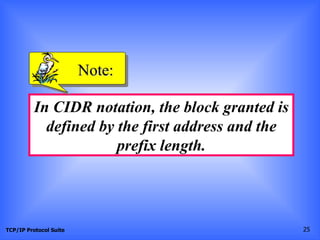
This document discusses classless addressing and variable-length subnetting. It begins by explaining that in classless addressing, variable-length blocks of IP addresses are assigned without class boundaries. It then provides examples of how to determine the network address, broadcast address, and number of addresses given a classless IP address and prefix length. The document also describes how organizations can create subnets within a granted address block to meet their needs using variable-length subnetting.
Here is the presentation for Network Layer Numericals from the book Andrew S. Tanenbaum (Computer Networks) and B A Forouzan ( Data Communication and Networking)
The Open Systems Interconnection model (OSI model) is a conceptual model that characterizes and standardizes the communication functions of a telecommunication or computing system without regard to their underlying internal structure and technology. Its goal is the interoperability of diverse communication systems with standard protocols. The model partitions a communication system into abstraction layers. The original version of the model defined seven layers.
This presentation contains why we need sub netting, how we do sub netting, CIDR, Subnet mask, Subnet mask value, Class A Sub netting, Class B Sub netting, Class C Sub netting.
Difference between OSI Layer & TCP/IP LayerNetwax Lab
Difference between OSI Layer & TCP/IP Layer
TCP/IP OSI
It has 4 layers. It has 7 layers.
TCP/IP Protocols are considered to be standards
around which the internet has developed.
OSI Model however is a "generic, protocolindependent standard."
Follows Vertical Approach Follows Horizontal Approach
In TCP/IP Model, Transport Layer does not
Guarantees delivery of packets.
In OSI Model, Transport Layer Guarantees
delivery of packets.
IPv4 (Internet Protocol Version 4). This silde will give u all information about IPv4.
Hope so you like it Freinds.
and
Sorry if i can fulfill ur wish in the given IPv4 Presentation.
hello everyone this a very interesting pps about general concepts of ip address here u can find lot of stuff and all those matter which u could not find even in a search engine
HOPE U LOVE IT
hey! everybody this is my third and last pps of this month and i ensure that this will definately guide you about ip address and its contain and what r all different kinds of ip r available with questions tags specified also. all thoes who u cannot find on any search engine u can get all stuff here!!!!!!
hope u loved it ???!@@@#
UiPath Test Automation using UiPath Test Suite series, part 4DianaGray10
Welcome to UiPath Test Automation using UiPath Test Suite series part 4. In this session, we will cover Test Manager overview along with SAP heatmap.
The UiPath Test Manager overview with SAP heatmap webinar offers a concise yet comprehensive exploration of the role of a Test Manager within SAP environments, coupled with the utilization of heatmaps for effective testing strategies.
Participants will gain insights into the responsibilities, challenges, and best practices associated with test management in SAP projects. Additionally, the webinar delves into the significance of heatmaps as a visual aid for identifying testing priorities, areas of risk, and resource allocation within SAP landscapes. Through this session, attendees can expect to enhance their understanding of test management principles while learning practical approaches to optimize testing processes in SAP environments using heatmap visualization techniques
What will you get from this session?
1. Insights into SAP testing best practices
2. Heatmap utilization for testing
3. Optimization of testing processes
4. Demo
Topics covered:
Execution from the test manager
Orchestrator execution result
Defect reporting
SAP heatmap example with demo
Speaker:
Deepak Rai, Automation Practice Lead, Boundaryless Group and UiPath MVP
The Art of the Pitch: WordPress Relationships and SalesLaura Byrne
Clients don’t know what they don’t know. What web solutions are right for them? How does WordPress come into the picture? How do you make sure you understand scope and timeline? What do you do if sometime changes?
All these questions and more will be explored as we talk about matching clients’ needs with what your agency offers without pulling teeth or pulling your hair out. Practical tips, and strategies for successful relationship building that leads to closing the deal.
Epistemic Interaction - tuning interfaces to provide information for AI supportAlan Dix
Paper presented at SYNERGY workshop at AVI 2024, Genoa, Italy. 3rd June 2024
https://alandix.com/academic/papers/synergy2024-epistemic/
As machine learning integrates deeper into human-computer interactions, the concept of epistemic interaction emerges, aiming to refine these interactions to enhance system adaptability. This approach encourages minor, intentional adjustments in user behaviour to enrich the data available for system learning. This paper introduces epistemic interaction within the context of human-system communication, illustrating how deliberate interaction design can improve system understanding and adaptation. Through concrete examples, we demonstrate the potential of epistemic interaction to significantly advance human-computer interaction by leveraging intuitive human communication strategies to inform system design and functionality, offering a novel pathway for enriching user-system engagements.
Generating a custom Ruby SDK for your web service or Rails API using Smithyg2nightmarescribd
Have you ever wanted a Ruby client API to communicate with your web service? Smithy is a protocol-agnostic language for defining services and SDKs. Smithy Ruby is an implementation of Smithy that generates a Ruby SDK using a Smithy model. In this talk, we will explore Smithy and Smithy Ruby to learn how to generate custom feature-rich SDKs that can communicate with any web service, such as a Rails JSON API.
JMeter webinar - integration with InfluxDB and GrafanaRTTS
Watch this recorded webinar about real-time monitoring of application performance. See how to integrate Apache JMeter, the open-source leader in performance testing, with InfluxDB, the open-source time-series database, and Grafana, the open-source analytics and visualization application.
In this webinar, we will review the benefits of leveraging InfluxDB and Grafana when executing load tests and demonstrate how these tools are used to visualize performance metrics.
Length: 30 minutes
Session Overview
-------------------------------------------
During this webinar, we will cover the following topics while demonstrating the integrations of JMeter, InfluxDB and Grafana:
- What out-of-the-box solutions are available for real-time monitoring JMeter tests?
- What are the benefits of integrating InfluxDB and Grafana into the load testing stack?
- Which features are provided by Grafana?
- Demonstration of InfluxDB and Grafana using a practice web application
To view the webinar recording, go to:
https://www.rttsweb.com/jmeter-integration-webinar
Builder.ai Founder Sachin Dev Duggal's Strategic Approach to Create an Innova...Ramesh Iyer
In today's fast-changing business world, Companies that adapt and embrace new ideas often need help to keep up with the competition. However, fostering a culture of innovation takes much work. It takes vision, leadership and willingness to take risks in the right proportion. Sachin Dev Duggal, co-founder of Builder.ai, has perfected the art of this balance, creating a company culture where creativity and growth are nurtured at each stage.
Dev Dives: Train smarter, not harder – active learning and UiPath LLMs for do...UiPathCommunity
💥 Speed, accuracy, and scaling – discover the superpowers of GenAI in action with UiPath Document Understanding and Communications Mining™:
See how to accelerate model training and optimize model performance with active learning
Learn about the latest enhancements to out-of-the-box document processing – with little to no training required
Get an exclusive demo of the new family of UiPath LLMs – GenAI models specialized for processing different types of documents and messages
This is a hands-on session specifically designed for automation developers and AI enthusiasts seeking to enhance their knowledge in leveraging the latest intelligent document processing capabilities offered by UiPath.
Speakers:
👨🏫 Andras Palfi, Senior Product Manager, UiPath
👩🏫 Lenka Dulovicova, Product Program Manager, UiPath
Smart TV Buyer Insights Survey 2024 by 91mobiles.pdf91mobiles
91mobiles recently conducted a Smart TV Buyer Insights Survey in which we asked over 3,000 respondents about the TV they own, aspects they look at on a new TV, and their TV buying preferences.
Accelerate your Kubernetes clusters with Varnish CachingThijs Feryn
A presentation about the usage and availability of Varnish on Kubernetes. This talk explores the capabilities of Varnish caching and shows how to use the Varnish Helm chart to deploy it to Kubernetes.
This presentation was delivered at K8SUG Singapore. See https://feryn.eu/presentations/accelerate-your-kubernetes-clusters-with-varnish-caching-k8sug-singapore-28-2024 for more details.
Software Delivery At the Speed of AI: Inflectra Invests In AI-Powered QualityInflectra
In this insightful webinar, Inflectra explores how artificial intelligence (AI) is transforming software development and testing. Discover how AI-powered tools are revolutionizing every stage of the software development lifecycle (SDLC), from design and prototyping to testing, deployment, and monitoring.
Learn about:
• The Future of Testing: How AI is shifting testing towards verification, analysis, and higher-level skills, while reducing repetitive tasks.
• Test Automation: How AI-powered test case generation, optimization, and self-healing tests are making testing more efficient and effective.
• Visual Testing: Explore the emerging capabilities of AI in visual testing and how it's set to revolutionize UI verification.
• Inflectra's AI Solutions: See demonstrations of Inflectra's cutting-edge AI tools like the ChatGPT plugin and Azure Open AI platform, designed to streamline your testing process.
Whether you're a developer, tester, or QA professional, this webinar will give you valuable insights into how AI is shaping the future of software delivery.
GDG Cloud Southlake #33: Boule & Rebala: Effective AppSec in SDLC using Deplo...James Anderson
Effective Application Security in Software Delivery lifecycle using Deployment Firewall and DBOM
The modern software delivery process (or the CI/CD process) includes many tools, distributed teams, open-source code, and cloud platforms. Constant focus on speed to release software to market, along with the traditional slow and manual security checks has caused gaps in continuous security as an important piece in the software supply chain. Today organizations feel more susceptible to external and internal cyber threats due to the vast attack surface in their applications supply chain and the lack of end-to-end governance and risk management.
The software team must secure its software delivery process to avoid vulnerability and security breaches. This needs to be achieved with existing tool chains and without extensive rework of the delivery processes. This talk will present strategies and techniques for providing visibility into the true risk of the existing vulnerabilities, preventing the introduction of security issues in the software, resolving vulnerabilities in production environments quickly, and capturing the deployment bill of materials (DBOM).
Speakers:
Bob Boule
Robert Boule is a technology enthusiast with PASSION for technology and making things work along with a knack for helping others understand how things work. He comes with around 20 years of solution engineering experience in application security, software continuous delivery, and SaaS platforms. He is known for his dynamic presentations in CI/CD and application security integrated in software delivery lifecycle.
Gopinath Rebala
Gopinath Rebala is the CTO of OpsMx, where he has overall responsibility for the machine learning and data processing architectures for Secure Software Delivery. Gopi also has a strong connection with our customers, leading design and architecture for strategic implementations. Gopi is a frequent speaker and well-known leader in continuous delivery and integrating security into software delivery.
GDG Cloud Southlake #33: Boule & Rebala: Effective AppSec in SDLC using Deplo...
Classless addressing
1. Chapter 5
IP Addresses:
Classless Addressing
Objectives
Upon completion you will be able to:
• Understand the concept of classless addressing
• Be able to find the first and last address given an IP address
• Be able to find the network address given a classless IP address
• Be able to create subnets from a block of classless IP addresses
• Understand address allocation and address aggregation
TCP/IP Protocol Suite 1
2. 5.1 VARIABLE-LENGTH BLOCKS
In classless addressing variable-length blocks are assigned that belong
to no class. In this architecture, the entire address space (232 addresses)
is divided into blocks of different sizes.
The topics discussed in this section include:
Restrictions
Finding the Block
Granted Block
TCP/IP Protocol Suite 2
3. Figure 5.1 Variable-length blocks
TCP/IP Protocol Suite 3
4. ExamplE 1
Which of the following can be the beginning address
of a block that contains 16 addresses?
a. 205.16.37.32 b.190.16.42.44
c. 17.17.33.80 d.123.45.24.52
Solution
Only two are eligible (a and c). The address
205.16.37.32 is eligible because 32 is divisible by 16.
The address 17.17.33.80 is eligible because 80 is
divisible by 16.
TCP/IP Protocol Suite 4
5. ExamplE 2
Which of the following can be the beginning address
of a block that contains 256 addresses?
a.205.16.37.32 b.190.16.42.0
c.17.17.32.0 d.123.45.24.52
Solution
In this case, the right-most byte must be 0. As we
mentioned in Chapter 4, the IP addresses use base
256 arithmetic. When the right-most byte is 0, the total
address is divisible by 256. Only two addresses are
eligible (b and c).
TCP/IP Protocol Suite 5
6. ExamplE 3
Which of the following can be the beginning address
of a block that contains 1024 addresses?
a. 205.16.37.32 b.190.16.42.0
c. 17.17.32.0 d.123.45.24.52
Solution
In this case, we need to check two bytes because
1024 = 4 × 256. The right-most byte must be divisible
by 256. The second byte (from the right) must be
divisible by 4. Only one address is eligible (c).
TCP/IP Protocol Suite 6
7. Figure 5.2 Format of classless addressing address
TCP/IP Protocol Suite 7
9. Note:
Classful addressing is a special case of
classless addressing.
TCP/IP Protocol Suite 9
10. ExamplE 4
What is the first address in the block if one of the
addresses is 167.199.170.82/27?
Solution
The prefix length is 27, which means that we must
keep the first 27 bits as is and change the remaining
bits (5) to 0s. The following shows the process:
Address in binary: 10100111 11000111 10101010 01010010
Keep the left 27 bits: 10100111 11000111 10101010 01000000
Result in CIDR notation: 167.199.170.64/27
TCP/IP Protocol Suite 10
11. ExamplE 5
What is the first address in the block if one of the
addresses is 140.120.84.24/20?
Solution
Figure 5.3 shows the solution. The first, second, and
fourth bytes are easy; for the third byte we keep the
bits corresponding to the number of 1s in that group.
The first address is 140.120.80.0/20.
See Next Slide
TCP/IP Protocol Suite 11
13. ExamplE 6
Find the first address in the block if one of the
addresses is 140.120.84.24/20.
Solution
The first, second, and fourth bytes are as defined in
the previous example. To find the third byte, we write
84 as the sum of powers of 2 and select only the
leftmost 4 (m is 4) as shown in Figure 5.4. The first
address is 140.120.80.0/20.
See Next Slide
TCP/IP Protocol Suite 13
15. ExamplE 7
Find the number of addresses in the block if one of
the addresses is 140.120.84.24/20.
Solution
The prefix length is 20. The number of addresses in
the block is 232−20 or 212 or 4096. Note that
this is a large block with 4096 addresses.
TCP/IP Protocol Suite 15
16. ExamplE 8
Using the first method, find the last address in the
block if one of the addresses is 140.120.84.24/20.
Solution
We found in the previous examples that the first
address is 140.120.80.0/20 and the number of
addresses is 4096. To find the last address, we need to
add 4095 (4096 − 1) to the first address.
See Next Slide
TCP/IP Protocol Suite 16
17. ExamplE 8 (Continued)
To keep the format in dotted-decimal notation, we
need to represent 4095 in base 256 (see Appendix B)
and do the calculation in base 256. We write 4095 as
15.255. We then add the first address to this number
(in base 255) to obtain the last address as shown
below:
140 . 120 . 80 . 0
15 . 255
-------------------------
140 . 120 . 95 . 255
The last address is 140.120.95.255/20.
TCP/IP Protocol Suite 17
18. ExamplE 9
Using the second method, find the last address in the
block if one of the addresses is 140.120.84.24/20.
Solution
The mask has twenty 1s and twelve 0s. The
complement of the mask has twenty 0s and twelve 1s.
In other words, the mask complement is
00000000 00000000 00001111 11111111
or 0.0.15.255. We add the mask complement to the
beginning address to find the last address.
See Next Slide
TCP/IP Protocol Suite 18
19. ExamplE 9 (Continued)
We add the mask complement to the beginning
address to find the last address.
140 . 120 . 80 . 0
0 . 0 . 15 . 255
----------------------------
140 . 120 . 95 . 255
The last address is 140.120.95.255/20.
TCP/IP Protocol Suite 19
20. ExamplE
10
Find the block if one of the addresses is
190.87.140.202/29.
Solution
We follow the procedure in the previous examples to
find the first address, the number of addresses, and
the last address. To find the first address, we notice
that the mask (/29) has five 1s in the last byte. So we
write the last byte as powers of 2 and retain only the
leftmost five as shown below:
See Next Slide
TCP/IP Protocol Suite 20
21. ExamplE 10 (Continued)
202 ➡ 128 + 64 + 0 + 0 + 8 + 0 + 2 + 0
The leftmost 5 numbers are ➡ 128 + 64 + 0 + 0 + 8
The first address is 190.87.140.200/29
The number of addresses is 232−29 or 8. To find the last address,
we use the complement of the mask. The mask has twenty-nine
1s; the complement has three 1s. The complement is 0.0.0.7. If
we add this to the first address, we get 190.87.140.207/29. In
other words, the first address is 190.87.140.200/29, the last
address is 190.87.140.207/20. There are only 8 addresses in
this block.
TCP/IP Protocol Suite 21
22. ExamplE
11
Show a network configuration for the block in the previous
example.
Solution
The organization that is granted the block in the previous
example can assign the addresses in the block to the hosts in its
network. However, the first address needs to be used as the
network address and the last address is kept as a special
address (limited broadcast address). Figure 5.5 shows how the
block can be used by an organization. Note that the last
address ends with 207, which is different from the 255 seen in
classful addressing.
See Next Slide
TCP/IP Protocol Suite 22
23. Figure 5.5 Example 11
TCP/IP Protocol Suite 23
24. Note:
In classless addressing, the last
address in the block does not
necessarily end in 255.
TCP/IP Protocol Suite 24
25. Note:
In CIDR notation, the block granted is
defined by the first address and the
prefix length.
TCP/IP Protocol Suite 25
26. 5.2 SUBNETTING
When an organization is granted a block of addresses, it can create
subnets to meet its needs. The prefix length increases to define the
subnet prefix length.
The topics discussed in this section include:
Finding the Subnet Mask
Finding the Subnet Addresses
Variable-Length Subnets
TCP/IP Protocol Suite 26
27. Note:
In fixed-length subnetting, the number
of subnets is a power of 2.
TCP/IP Protocol Suite 27
28. ExamplE
12
An organization is granted the block 130.34.12.64/26.
The organization needs 4 subnets. What is the subnet
prefix length?
Solution
We need 4 subnets, which means we need to add two
more 1s (log2 4 = 2) to the site prefix. The subnet
prefix is then /28.
TCP/IP Protocol Suite 28
29. ExamplE
13
What are the subnet addresses and the range of
addresses for each subnet in the previous example?
Solution
Figure 5.6 shows one configuration.
See Next Slide
TCP/IP Protocol Suite 29
30. Figure 5.6 Example 13
TCP/IP Protocol Suite 30
31. ExamplE 13 (ContinuEd)
The site has 232−26 = 64 addresses. Each subnet has
232–28 = 16 addresses. Now let us find the first and last
address in each subnet.
1. The first address in the first subnet is 130.34.12.64/28,
using the procedure we showed in the previous examples.
Note that the first address of the first subnet is the first
address of the block. The last address of the subnet can
be found by adding 15 (16 −1) to the first address. The
last address is 130.34.12.79/28.
See Next Slide
TCP/IP Protocol Suite 31
32. ExamplE 13 (ContinuEd)
2.The first address in the second subnet is
130.34.12.80/28; it is found by adding 1 to the last
address of the previous subnet. Again adding 15 to
the first address, we obtain the last address,
130.34.12.95/28.
3. Similarly, we find the first address of the third
subnet to be 130.34.12.96/28 and the last to be
130.34.12.111/28.
4. Similarly, we find the first address of the fourth
subnet to be 130.34.12.112/28 and the last to be
130.34.12.127/28.
TCP/IP Protocol Suite 32
33. ExamplE
14
An organization is granted a block of addresses with the
beginning address 14.24.74.0/24. There are 232−24= 256
addresses in this block. The organization needs to have 11
subnets as shown below:
a. two subnets, each with 64 addresses.
b. two subnets, each with 32 addresses.
c. three subnets, each with 16 addresses.
d. four subnets, each with 4 addresses.
Design the subnets.
See Next Slide For One Solution
TCP/IP Protocol Suite 33
34. Figure 5.7 Example 14
TCP/IP Protocol Suite 34
35. ExamplE 14 (ContinutEd)
1. We use the first 128 addresses for the first two
subnets, each with 64 addresses. Note that the mask
for each network is /26. The subnet address for each
subnet is given in the figure.
2. We use the next 64 addresses for the next two
subnets, each with 32 addresses. Note that the mask
for each network is /27. The subnet address for each
subnet is given in the figure.
See Next Slide
TCP/IP Protocol Suite 35
36. ExamplE 14 (ContinutEd)
3. We use the next 48 addresses for the next three
subnets, each with 16 addresses. Note that the mask
for each network is /28. The subnet address for each
subnet is given in the figure.
4. We use the last 16 addresses for the last four
subnets, each with 4 addresses. Note that the mask for
each network is /30. The subnet address for each
subnet is given in the figure.
TCP/IP Protocol Suite 36
37. ExamplE
15
As another example, assume a company has three
offices: Central, East, and West. The Central office is
connected to the East and West offices via private,
point-to-point WAN lines. The company is granted a
block of 64 addresses with the beginning address
70.12.100.128/26. The management has decided to
allocate 32 addresses for the Central office and
divides the rest of addresses between the two offices.
Figure 5.8 shows the configuration designed by the
management.
See Next Slide
TCP/IP Protocol Suite 37
38. Figure 5.8 Example 15
TCP/IP Protocol Suite 38
39. ExamplE 15 (ContinuEd)
The company will have three subnets, one at Central, one at
East, and one at West. The following lists the subblocks
allocated for each network:
a. The Central office uses the network address
70.12.100.128/27. This is the first address, and the mask
/27 shows that there are 32 addresses in this network.
Note that three of these addresses are used for the
routers and the company has reserved the last address
in the sub-block. The addresses in this subnet are
70.12.100.128/27 to 70.12.100.159/27. Note that the
interface of the router that connects the Central subnet
to the WAN needs no address because it is a point-to-
point connection.
TCP/IP Protocol Suite
See Next Slide 39
40. ExamplE 15 (ContinuEd)
b. The West office uses the network address
70.12.100.160/28. The mask /28 shows that there are
only 16 addresses in this network. Note that one of
these addresses is used for the router and the company
has reserved the last address in the sub-block. The
addresses in this subnet are 70.12.100.160/28 to
70.12.100.175/28. Note also that the interface of the
router that connects the West subnet to the WAN needs
no address because it is a point-to- point connection.
See Next Slide
TCP/IP Protocol Suite 40
41. ExamplE 15 (ContinuEd)
c. The East office uses the network address
70.12.100.176/28. The mask /28 shows that there are
only 16 addresses in this network. Note that one of
these addresses is used for the router and the company
has reserved the last address in the sub-block. The
addresses in. this subnet are 70.12.100.176/28 to
70.12.100.191/28. Note also that the interface of the
router that connects the East subnet to the WAN needs
no address because it is a point-to-point connection.
TCP/IP Protocol Suite 41
42. 5.3 ADDRESS ALLOCATION
Address allocation is the responsibility of a global authority called the
Internet Corporation for Assigned Names and Addresses (ICANN). It
usually assigns a large block of addresses to an ISP to be distributed to
its Internet users.
TCP/IP Protocol Suite 42
43. ExamplE
16
An ISP is granted a block of addresses starting with
190.100.0.0/16 (65,536 addresses). The ISP needs to
distribute these addresses to three groups of
customers as follows:
a. The first group has 64 customers; each needs 256
addresses.
b. The second group has 128 customers; each needs 128
addresses
c. The third group has 128 customers; each needs 64
addresses.
See Next Slide
TCP/IP Protocol Suite 43
44. ExamplE 16 (ContinuEd)
Design the subblocks and find out how many
addresses are still available after these allocations.
Solution
Figure 5.9 shows the situation.
See Next Slide
TCP/IP Protocol Suite 44
45. Figure 5.9 Example 16
TCP/IP Protocol Suite 45
46. ExamplE 16 (ContinuEd)
Group 1
For this group, each customer needs 256 addresses.
This means the suffix length is 8 (28 =256). The prefix
length is then 32 − 8 = 24. The addresses are:
1st Customer 190.100.0.0/24 190.100.0.255/24
2nd Customer 190.100.1.0/24 190.100.1.255/24
...
64th Customer 190.100.63.0/24 190.100.63.255/24
Total = 64 × 256 = 16,384
See Next Slide
TCP/IP Protocol Suite 46
47. ExamplE 16 (ContinuEd)
Group 2
For this group, each customer needs 128 addresses.
This means the suffix length is 7 (27 =128). The prefix
length is then 32 − 7 = 25. The addresses are:
1st Customer 190.100.64.0/25 190.100.64.127/25
2nd Customer 190.100.64.128/25 190.100.64.255/25
···
128th Customer 190.100.127.128/25 190.100.127.255/25
Total = 128 × 128 = 16,384
See Next Slide
TCP/IP Protocol Suite 47
48. ExamplE 16 (ContinuEd)
Group 3
For this group, each customer needs 64 addresses.
This means the suffix length is 6 (26 = 64). The prefix
length is then 32 − 6 = 26. The addresses are:
1st Customer 190.100.128.0/26 190.100.128.63/26
2nd Customer 190.100.128.64/26 190.100.128.127/26
···
128th Customer 190.100.159.192/26 190.100.159.255/26
Total = 128 × 64 = 8,192
See Next Slide
TCP/IP Protocol Suite 48
49. ExamplE 16 (ContinuEd)
Number of granted addresses to the ISP: 65,536
Number of allocated addresses by the ISP: 40,960
Number of available addresses: 24,576
TCP/IP Protocol Suite 49