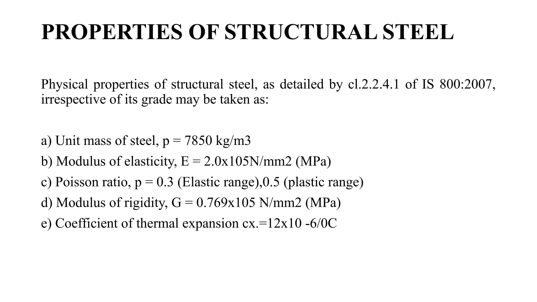
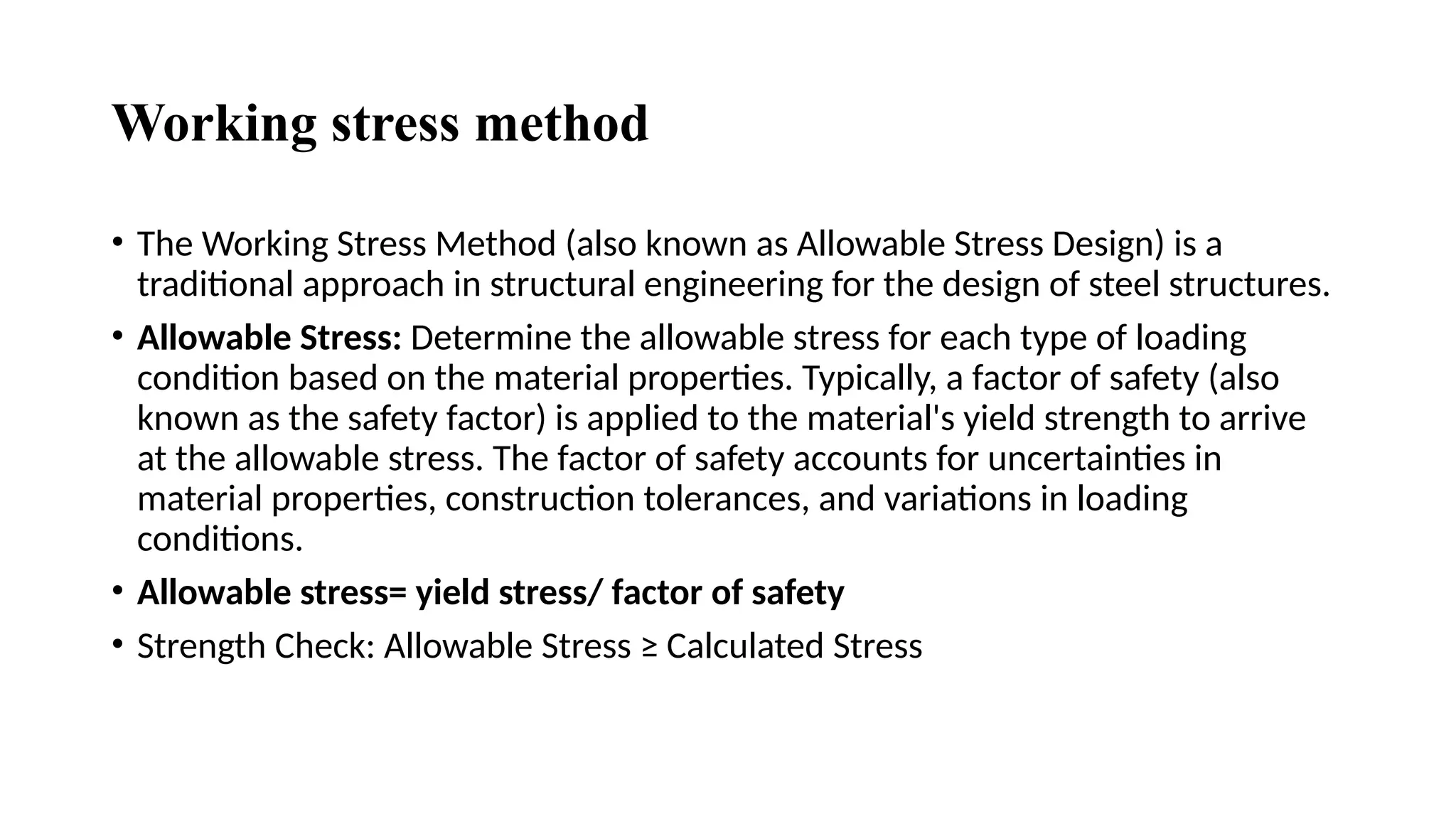
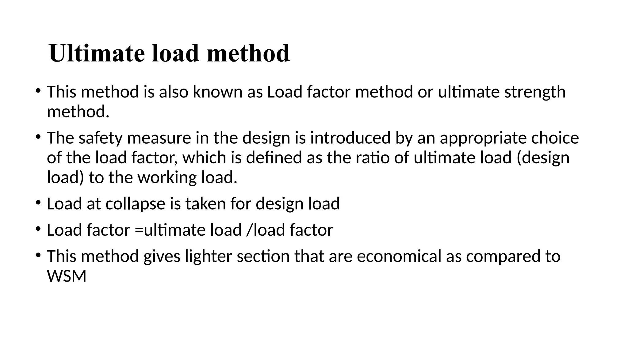
1.Title of the seminar: Liquefaction Phenomenon and
Mitigation Strategies for Soil Engineering
2.Faculty name: Tapaswini Dash
3.designation: Asst.prof.
4.Department: Civil Engineering
5:Outcome: By the end of this seminar, participants will
be able to
OUTLINE
Introduction
Causes of Liquefaction
Understanding Liquefaction
Effects of Liquefaction
Liquefaction Susceptibility
Identifying Liquefaction Risks
Mitigation Strategies
conclusion
References
INTRODUCTION TO STEEL STRUCTURE
• A steel structure is a framework composed of steel members, designed and
assembled to support various loads and provide structural integrity. Steel
structures are widely used in construction due to their strength, durability,
versatility and cost-effectiveness
• They are employed in a variety of applications, ranging from residential and
commercial buildings to industrial facilities, bridges, and other infrastructure
projects.
• Steel structures offer benefits such as high strength-to-weight ratio, speed of
construction, and the ability to recycle, making them an attractive choice for a
wide range of applications.
• Design properly a structure without affecting safety with cost effective way.
COMMON STEEL STRUCTURES
. Industrial Structures
.Steel Framed Buildings
. Railway Bridges
.Transmission Towers etc.
These examples highlight the versatility of steel in construction, adapting to
various needs and requirements in different industries..
PROPERTIES OF STRUCTURAL STEEL
Physical properties of structural steel, as detailed by cl.2.2.4.1 of IS 800:2007,
irrespective of its grade may be taken as:
a) Unit mass of steel, p = 7850 kg/m3
b) Modulus of elasticity, E = 2.0x10⁵N/mm2 (MPa)
c) Poisson ratio, p = 0.3 (Elastic range),0.5 (plastic range)
d) Modulus of rigidity, G = 0.769x10⁵ N/mm2 (MPa)
e) Coefficient of thermal expansion cx.=12x10 -6/0C
LOADS ON STRUCTURES
• Dead Load (DL)
• Live Load (LL)
• Snow Load
• Wind Load
• Seismic Load
COMBINATION OF LOAD
As per IS 800: 2007, the load combinations for the ultimate limit state (ULS)
and serviceability limit state (SLS) are specified. The basic load combinations
for ULS are typically expressed in terms of factors applied to various loads.
• For Gravity Loads:
• 1.5×Dead Load+1.5×Live Load1.5×Dead Load+1.5×Live Load
• For Wind Loads:
• 1.5×Dead Load+1.5×Wind Load1.5×Dead Load+1.5×Wind Load
• For Earthquake Loads (Seismic Loads):
• 1.5×Dead Load+1.5×Earthquake Load1.5×Dead Load+1.5×Earthquake Load
• For Wind and Earthquake Loads Combined:
• 1.5×Dead Load+1.5×Wind Load+1.5×Earthquake Load1.5×Dead Load+1.5×Wind Load+
1.5×Earthquake Load
• The specific load combinations for serviceability may vary based on
the design codes and standards adopted for a particular project.
• 1.0×Dead Load+1.0×Live Load
DESIGN PHILOSOPHY OF STEEL STRUCTURE
• The design philosophy of steel structures involves principles
and considerations that aim to ensure safety, efficiency, and
functionality.
• Working Stress Method (WSM) The working stress method is
used to design structures made of reinforced concrete, steel,
and wood. ...
• Ultimate Load Method. This design philosophy is also called
the ultimate strength method or the load factor method. ...
• Limit State Method.
STRESS-STRAIN BEHAVIOR OF MILD STEEL
Working stress method
• The Working Stress Method (also known as Allowable Stress Design) is a
traditional approach in structural engineering for the design of steel structures.
• Allowable Stress: Determine the allowable stress for each type of loading
condition based on the material properties. Typically, a factor of safety (also
known as the safety factor) is applied to the material's yield strength to arrive
at the allowable stress. The factor of safety accounts for uncertainties in
material properties, construction tolerances, and variations in loading
conditions.
• Allowable stress= yield stress/ factor of safety
• Strength Check: Allowable Stress ≥ Calculated Stress
Ultimate load method
• This method is also known as Load factor method or ultimate strength
method.
• The safety measure in the design is introduced by an appropriate choice
of the load factor, which is defined as the ratio of ultimate load (design
load) to the working load.
• Load at collapse is taken for design load
• Load factor =ultimate load /load factor
• This method gives lighter section that are economical as compared to
WSM
Limit state method
• The Limit State Method is a structural engineering design philosophy
used in the analysis and design of structures.
• It is widely employed in the design of buildings, bridges, and other
civil engineering structures to ensure safety and performance under
various loading conditions.
• The key concept behind the Limit State Method is to identify and
consider different limit states, both in terms of strength and
serviceability, to ensure that a structure performs adequately
throughout its intended life.
There are two types of limit state method
Limit state of collapse
Limit state of serviceability
Some steel structures
Trumpet bridge in puri district Howrah bridge
Statue of unity
REFERENCES BOOKS AND CODES
• Design of Steel Structures Book by S. K. Duggal
• Design of Steel Structures Book by N.Subramanian
• Design of Steel Structures Book by S.S Bhavicati
• Code book –IS 800-2007 (limit state method of design)
• Steel table
THANK YOU

civil engineering/geotechnical engineering

  • 1.
    1.Title of theseminar: Liquefaction Phenomenon and Mitigation Strategies for Soil Engineering 2.Faculty name: Tapaswini Dash 3.designation: Asst.prof. 4.Department: Civil Engineering 5:Outcome: By the end of this seminar, participants will be able to
  • 2.
    OUTLINE Introduction Causes of Liquefaction UnderstandingLiquefaction Effects of Liquefaction Liquefaction Susceptibility Identifying Liquefaction Risks Mitigation Strategies conclusion References
  • 3.
    INTRODUCTION TO STEELSTRUCTURE • A steel structure is a framework composed of steel members, designed and assembled to support various loads and provide structural integrity. Steel structures are widely used in construction due to their strength, durability, versatility and cost-effectiveness • They are employed in a variety of applications, ranging from residential and commercial buildings to industrial facilities, bridges, and other infrastructure projects. • Steel structures offer benefits such as high strength-to-weight ratio, speed of construction, and the ability to recycle, making them an attractive choice for a wide range of applications. • Design properly a structure without affecting safety with cost effective way.
  • 4.
    COMMON STEEL STRUCTURES .Industrial Structures .Steel Framed Buildings . Railway Bridges .Transmission Towers etc. These examples highlight the versatility of steel in construction, adapting to various needs and requirements in different industries..
  • 5.
    PROPERTIES OF STRUCTURALSTEEL Physical properties of structural steel, as detailed by cl.2.2.4.1 of IS 800:2007, irrespective of its grade may be taken as: a) Unit mass of steel, p = 7850 kg/m3 b) Modulus of elasticity, E = 2.0x10⁵N/mm2 (MPa) c) Poisson ratio, p = 0.3 (Elastic range),0.5 (plastic range) d) Modulus of rigidity, G = 0.769x10⁵ N/mm2 (MPa) e) Coefficient of thermal expansion cx.=12x10 -6/0C
  • 6.
    LOADS ON STRUCTURES •Dead Load (DL) • Live Load (LL) • Snow Load • Wind Load • Seismic Load
  • 7.
    COMBINATION OF LOAD Asper IS 800: 2007, the load combinations for the ultimate limit state (ULS) and serviceability limit state (SLS) are specified. The basic load combinations for ULS are typically expressed in terms of factors applied to various loads. • For Gravity Loads: • 1.5×Dead Load+1.5×Live Load1.5×Dead Load+1.5×Live Load • For Wind Loads: • 1.5×Dead Load+1.5×Wind Load1.5×Dead Load+1.5×Wind Load • For Earthquake Loads (Seismic Loads): • 1.5×Dead Load+1.5×Earthquake Load1.5×Dead Load+1.5×Earthquake Load • For Wind and Earthquake Loads Combined: • 1.5×Dead Load+1.5×Wind Load+1.5×Earthquake Load1.5×Dead Load+1.5×Wind Load+ 1.5×Earthquake Load
  • 8.
    • The specificload combinations for serviceability may vary based on the design codes and standards adopted for a particular project. • 1.0×Dead Load+1.0×Live Load
  • 9.
    DESIGN PHILOSOPHY OFSTEEL STRUCTURE • The design philosophy of steel structures involves principles and considerations that aim to ensure safety, efficiency, and functionality. • Working Stress Method (WSM) The working stress method is used to design structures made of reinforced concrete, steel, and wood. ... • Ultimate Load Method. This design philosophy is also called the ultimate strength method or the load factor method. ... • Limit State Method.
  • 10.
  • 11.
    Working stress method •The Working Stress Method (also known as Allowable Stress Design) is a traditional approach in structural engineering for the design of steel structures. • Allowable Stress: Determine the allowable stress for each type of loading condition based on the material properties. Typically, a factor of safety (also known as the safety factor) is applied to the material's yield strength to arrive at the allowable stress. The factor of safety accounts for uncertainties in material properties, construction tolerances, and variations in loading conditions. • Allowable stress= yield stress/ factor of safety • Strength Check: Allowable Stress ≥ Calculated Stress
  • 12.
    Ultimate load method •This method is also known as Load factor method or ultimate strength method. • The safety measure in the design is introduced by an appropriate choice of the load factor, which is defined as the ratio of ultimate load (design load) to the working load. • Load at collapse is taken for design load • Load factor =ultimate load /load factor • This method gives lighter section that are economical as compared to WSM
  • 13.
    Limit state method •The Limit State Method is a structural engineering design philosophy used in the analysis and design of structures. • It is widely employed in the design of buildings, bridges, and other civil engineering structures to ensure safety and performance under various loading conditions. • The key concept behind the Limit State Method is to identify and consider different limit states, both in terms of strength and serviceability, to ensure that a structure performs adequately throughout its intended life.
  • 14.
    There are twotypes of limit state method Limit state of collapse Limit state of serviceability
  • 15.
    Some steel structures Trumpetbridge in puri district Howrah bridge Statue of unity
  • 16.
    REFERENCES BOOKS ANDCODES • Design of Steel Structures Book by S. K. Duggal • Design of Steel Structures Book by N.Subramanian • Design of Steel Structures Book by S.S Bhavicati • Code book –IS 800-2007 (limit state method of design) • Steel table
  • 17.