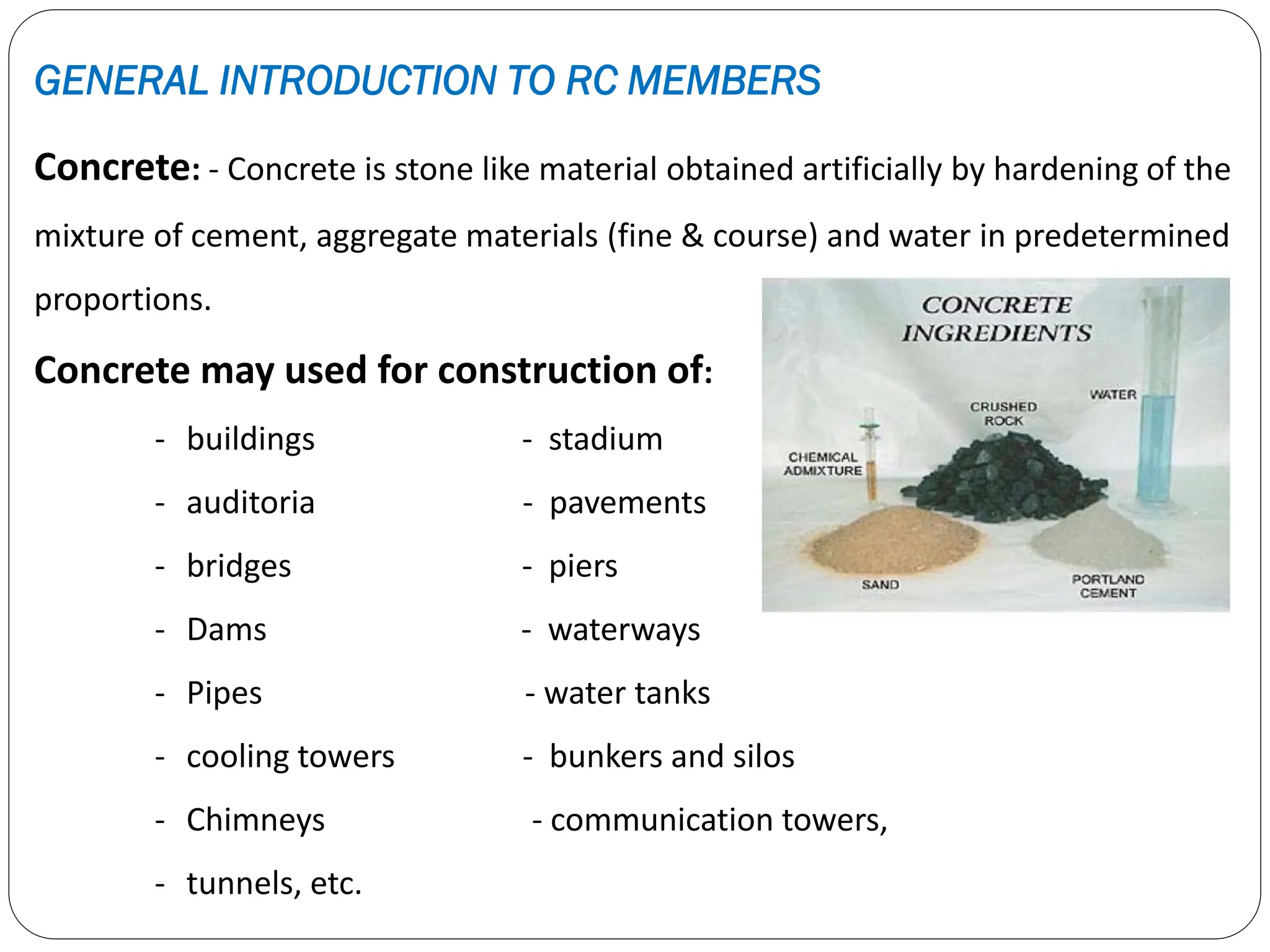
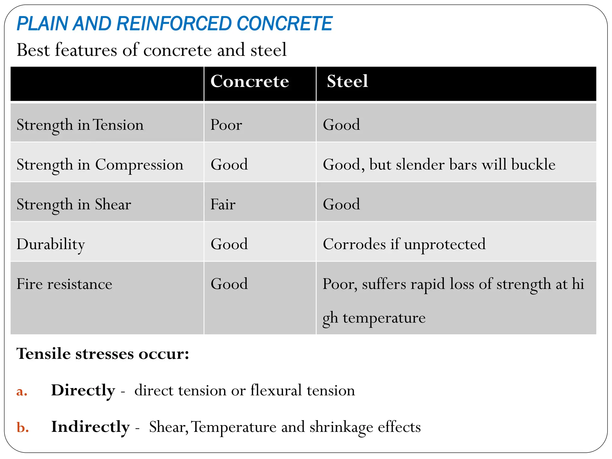
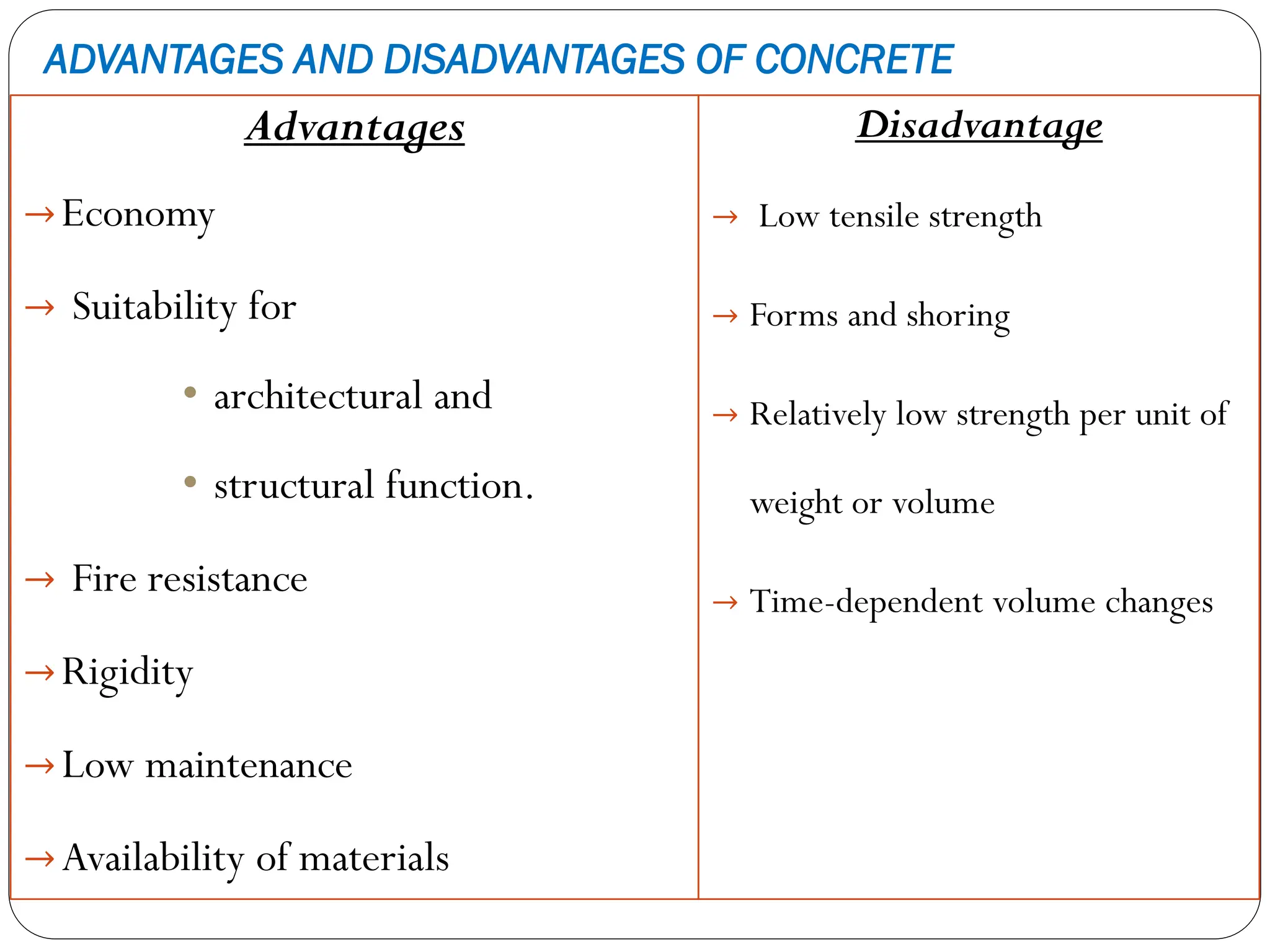
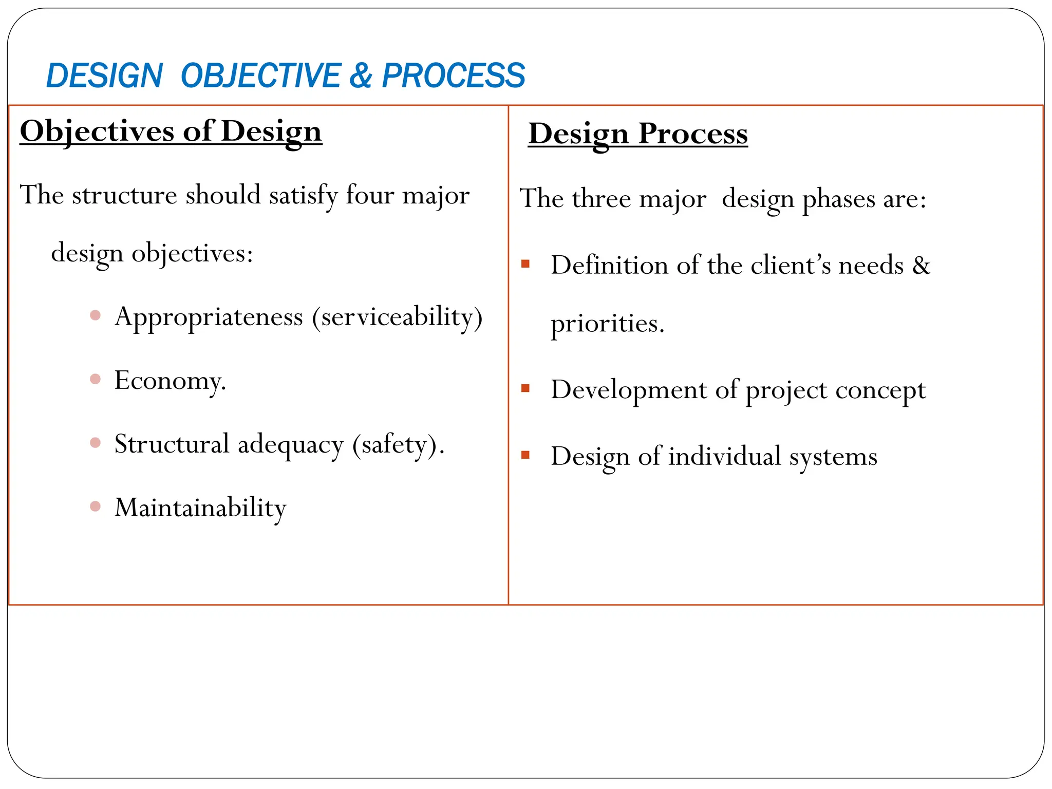
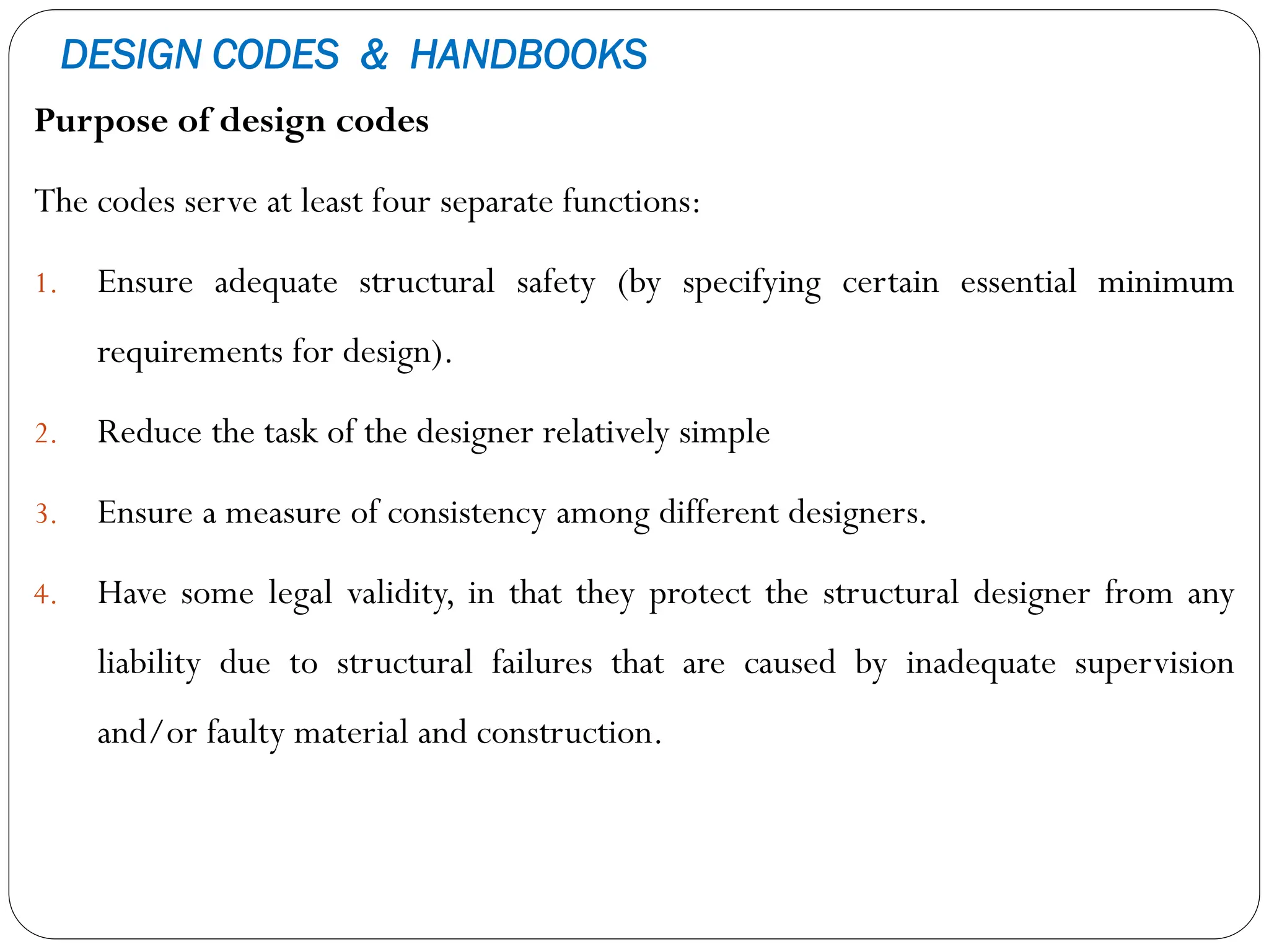
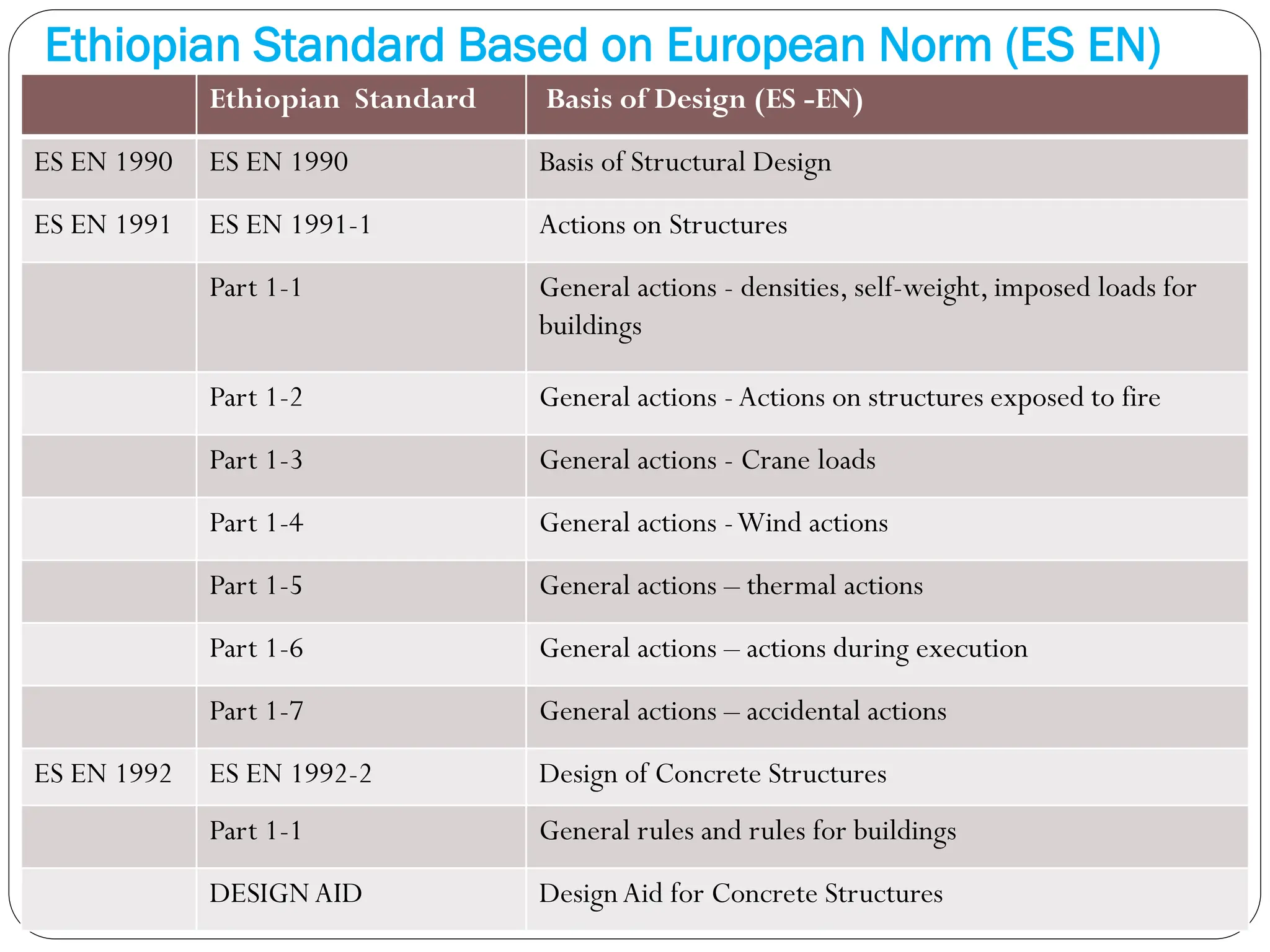
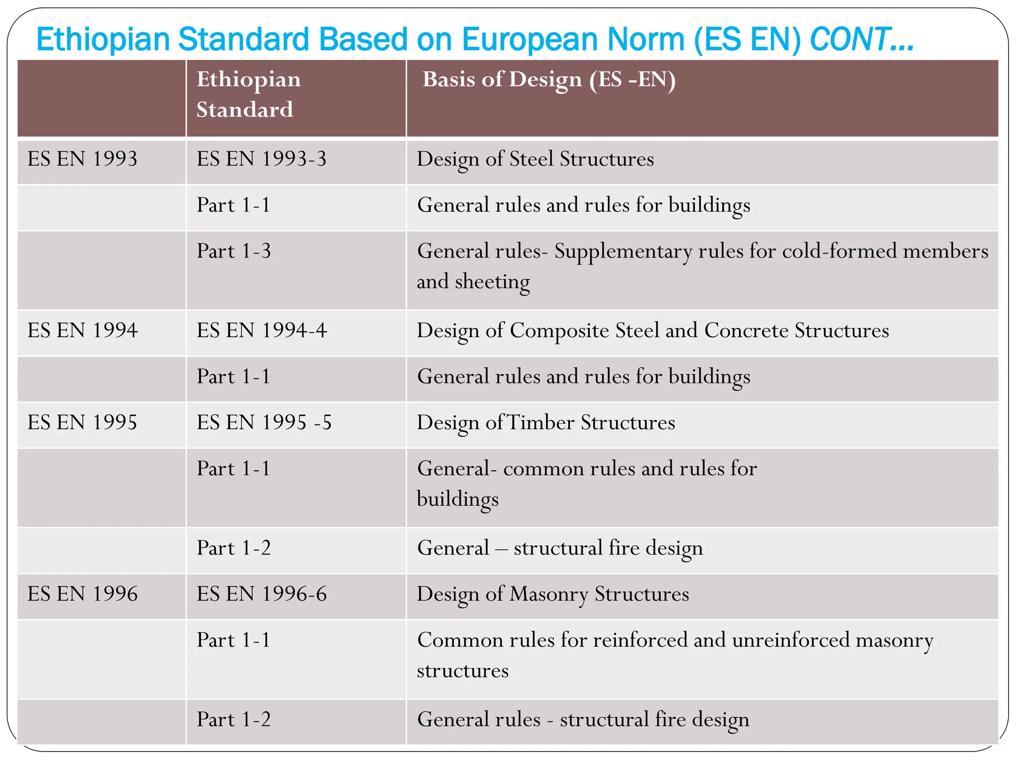
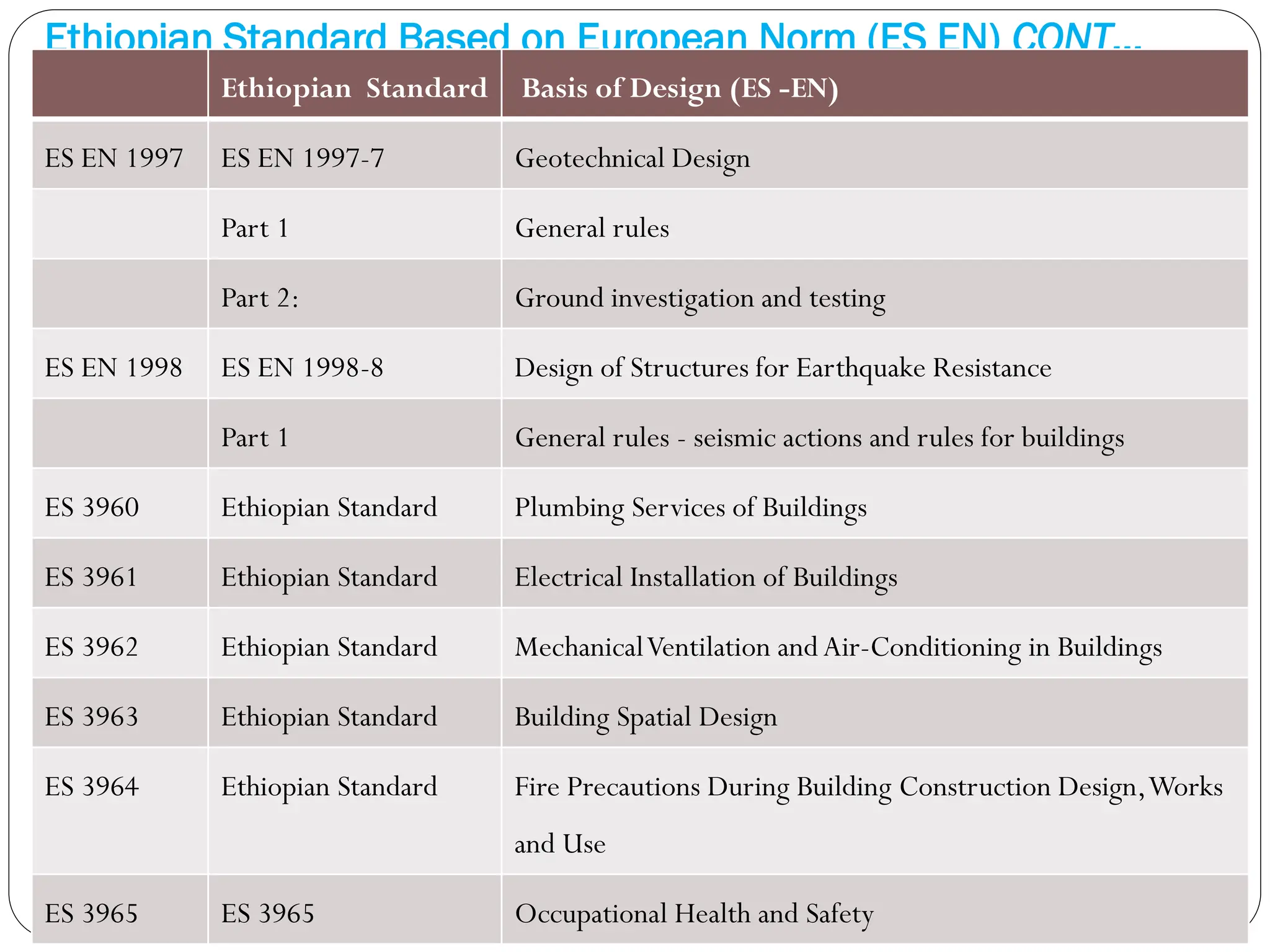
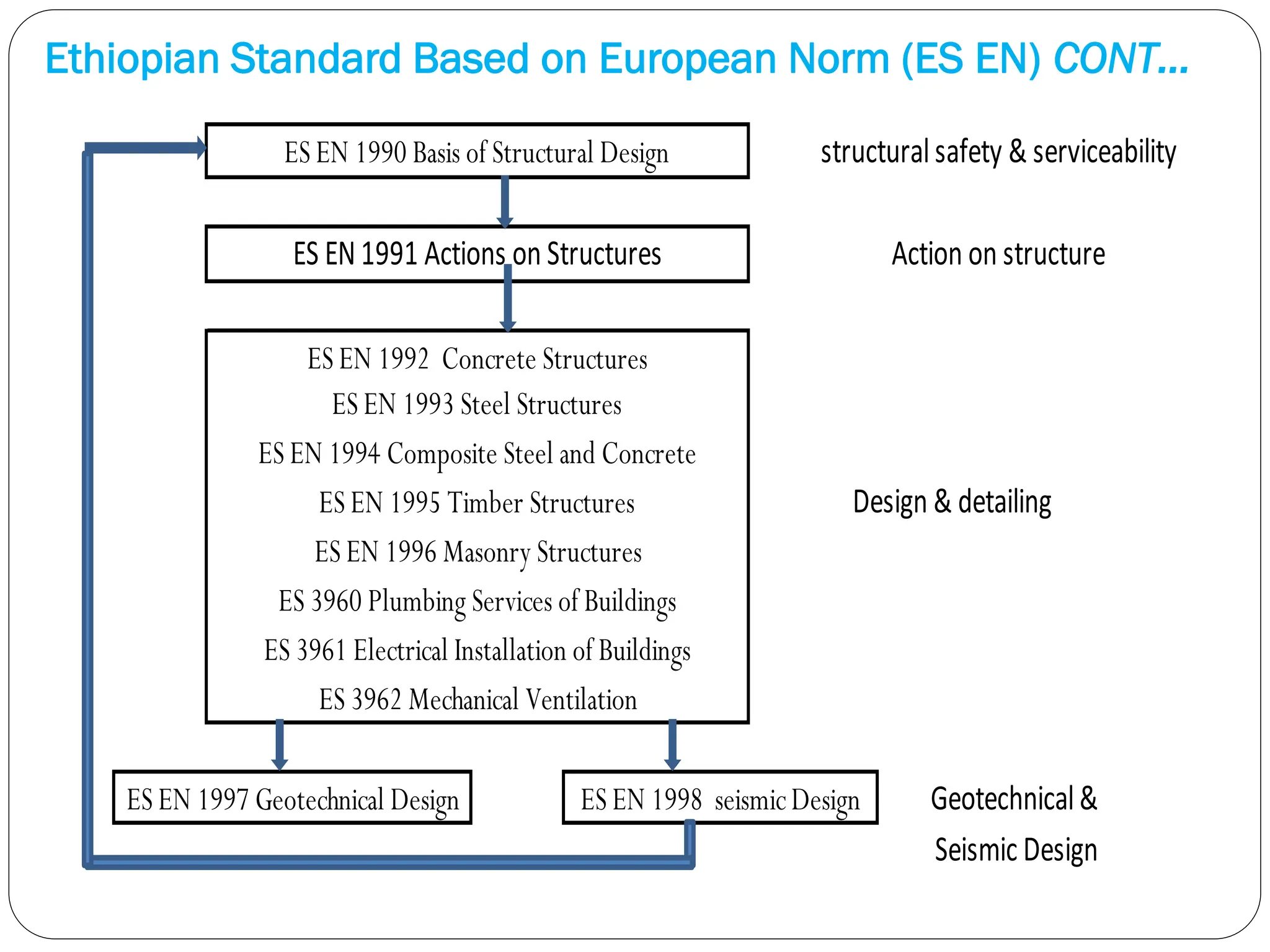
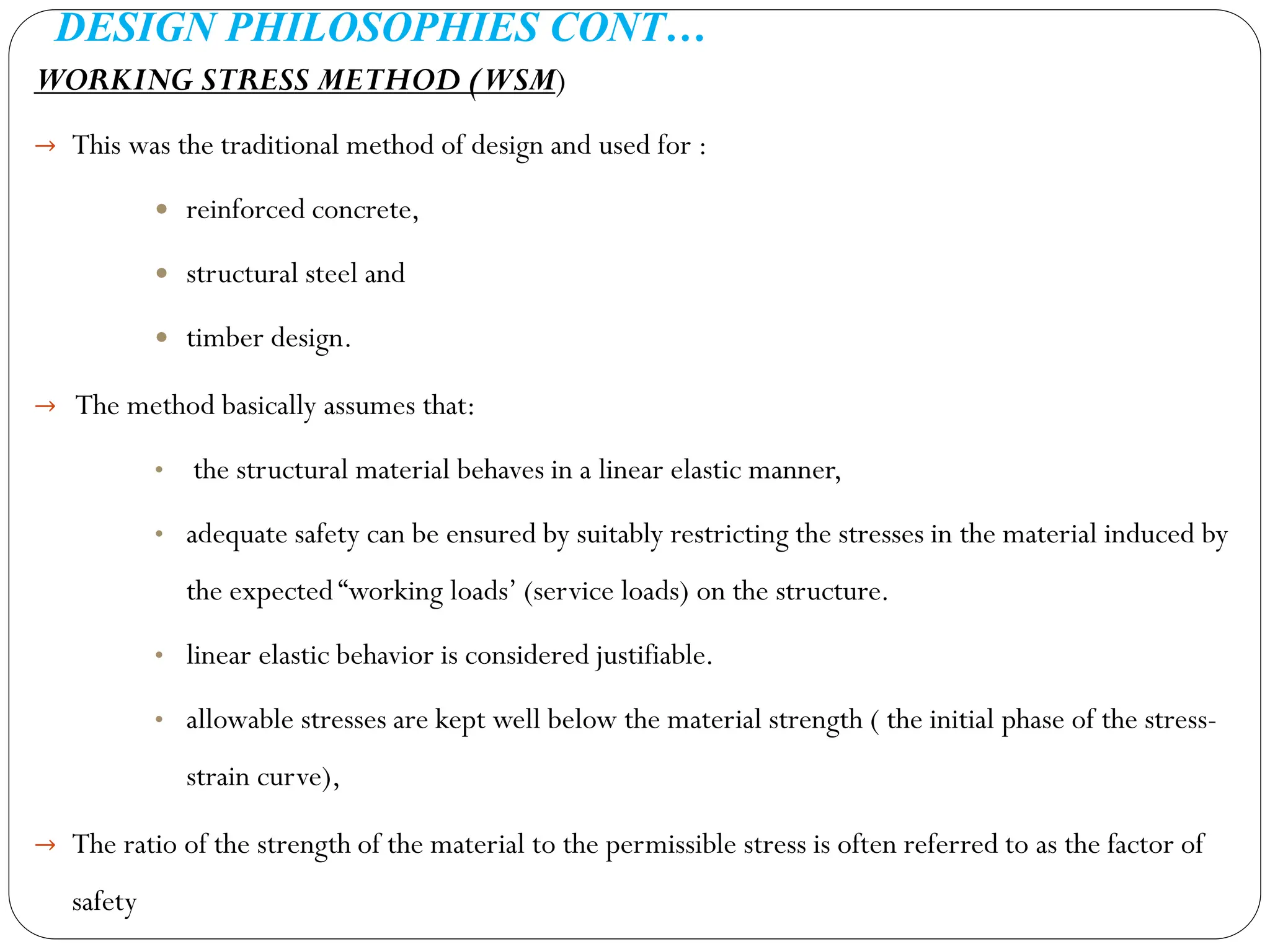
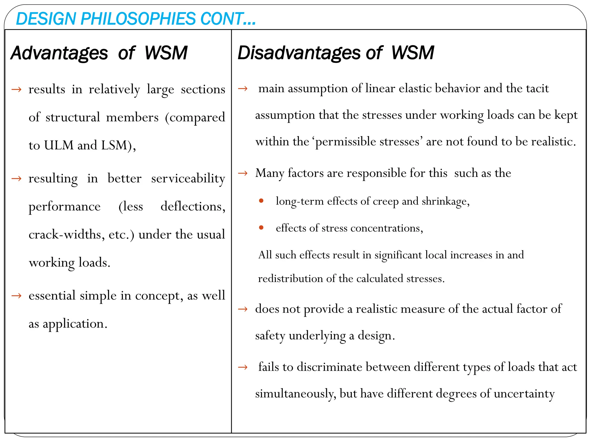
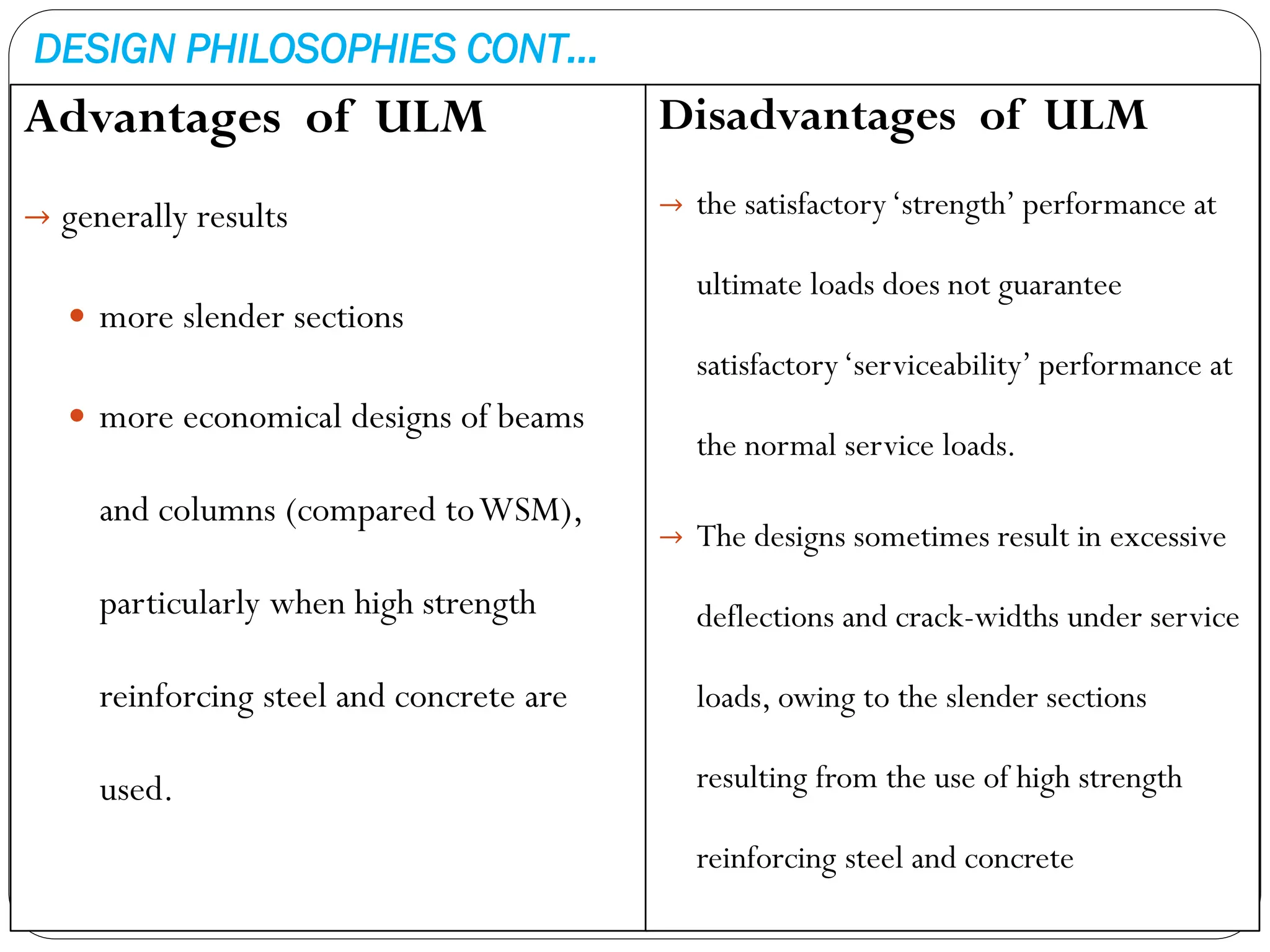
REINFORCED CONCRETE STRUCTURE
CHAPTER ONE:
Structure
.
Introduction to
Reinforced Concrete
University Of Gondar(IOT)
Civil Engineering
En. Berhanu Tena
Presentation
outline
• General Introduction to RC Members
• The Design Process
• Introduction to Ethiopian Standards
• Design Philosophies
GENERAL INTRODUCTION TO RC MEMBERS
Concrete: - Concrete is stone like material obtained artificially by hardening of the
mixture of cement, aggregate materials (fine & course) and water in predetermined
proportions.
Concrete may used for construction of:
- buildings - stadium
- auditoria - pavements
- bridges - piers
- Dams - waterways
- Pipes - water tanks
- cooling towers - bunkers and silos
- Chimneys - communication towers,
- tunnels, etc.
PLAIN AND REINFORCED CONCRETE
a. Plain Concrete: concrete structure without reinforcing bars.
b. Reinforced Concrete: concrete with steel bars embedded in the section.
What are the advantages of the reinforcing steel bar embedded in the section?
 Effectively taking up all the tension without separating from the concrete, since
concrete is weak in tension.
 The bond between steel and the surrounding concrete ensures strain compatibility
(strain at any point in the steel is equal to that in the adjoining concrete).
 the reinforcing steel imparts ductility to a material.
PLAIN AND REINFORCED CONCRETE
Best features of concrete and steel
Tensile stresses occur:
a. Directly - direct tension or flexural tension
b. Indirectly - Shear,Temperature and shrinkage effects
Concrete Steel
Strength inTension Poor Good
Strength in Compression Good Good, but slender bars will buckle
Strength in Shear Fair Good
Durability Good Corrodes if unprotected
Fire resistance Good Poor, suffers rapid loss of strength at hi
gh temperature
ADVANTAGES AND DISADVANTAGES OF CONCRETE
Advantages
→Economy
→ Suitability for
• architectural and
• structural function.
→ Fire resistance
→Rigidity
→Low maintenance
→Availability of materials
Disadvantage
→ Low tensile strength
→ Forms and shoring
→ Relatively low strength per unit of
weight or volume
→ Time-dependent volume changes
DESIGN OBJECTIVE & PROCESS
Objectives of Design
The structure should satisfy four major
design objectives:
 Appropriateness (serviceability)
 Economy.
 Structural adequacy (safety).
 Maintainability
Design Process
The three major design phases are:
 Definition of the client’s needs &
priorities.
 Development of project concept
 Design of individual systems
DESIGN CODES & HANDBOOKS
Purpose of design codes
The codes serve at least four separate functions:
1. Ensure adequate structural safety (by specifying certain essential minimum
requirements for design).
2. Reduce the task of the designer relatively simple
3. Ensure a measure of consistency among different designers.
4. Have some legal validity, in that they protect the structural designer from any
liability due to structural failures that are caused by inadequate supervision
and/or faulty material and construction.
Ethiopian Standard Based on European Norm (ES EN)
.
Ethiopian Standard Basis of Design (ES -EN)
ES EN 1990 ES EN 1990 Basis of Structural Design
ES EN 1991 ES EN 1991-1 Actions on Structures
Part 1-1 General actions - densities, self-weight, imposed loads for
buildings
Part 1-2 General actions -Actions on structures exposed to fire
Part 1-3 General actions - Crane loads
Part 1-4 General actions -Wind actions
Part 1-5 General actions – thermal actions
Part 1-6 General actions – actions during execution
Part 1-7 General actions – accidental actions
ES EN 1992 ES EN 1992-2 Design of Concrete Structures
Part 1-1 General rules and rules for buildings
DESIGNAID DesignAid for Concrete Structures
Ethiopian Standard Based on European Norm (ES EN) CONT…
Ethiopian
Standard
Basis of Design (ES -EN)
ES EN 1993 ES EN 1993-3 Design of Steel Structures
Part 1-1 General rules and rules for buildings
Part 1-3 General rules- Supplementary rules for cold-formed members
and sheeting
ES EN 1994 ES EN 1994-4 Design of Composite Steel and Concrete Structures
Part 1-1 General rules and rules for buildings
ES EN 1995 ES EN 1995 -5 Design ofTimber Structures
Part 1-1 General- common rules and rules for
buildings
Part 1-2 General – structural fire design
ES EN 1996 ES EN 1996-6 Design of Masonry Structures
Part 1-1 Common rules for reinforced and unreinforced masonry
structures
Part 1-2 General rules - structural fire design
Ethiopian Standard Based on European Norm (ES EN) CONT…
Ethiopian Standard Basis of Design (ES -EN)
ES EN 1997 ES EN 1997-7 Geotechnical Design
Part 1 General rules
Part 2: Ground investigation and testing
ES EN 1998 ES EN 1998-8 Design of Structures for Earthquake Resistance
Part 1 General rules - seismic actions and rules for buildings
ES 3960 Ethiopian Standard Plumbing Services of Buildings
ES 3961 Ethiopian Standard Electrical Installation of Buildings
ES 3962 Ethiopian Standard MechanicalVentilation andAir-Conditioning in Buildings
ES 3963 Ethiopian Standard Building Spatial Design
ES 3964 Ethiopian Standard Fire Precautions During Building Construction Design,Works
and Use
ES 3965 ES 3965 Occupational Health and Safety
Ethiopian Standard Based on European Norm (ES EN) CONT…
Seismic Design
ES EN 1995 Timber Structures
ES 3962 Mechanical Ventilation
ES EN1991 Actions on Structures
ES EN 1990 Basis of Structural Design
ES EN 1997 Geotechnical Design ES EN 1998 seismicDesign
ES EN 1992 Concrete Structures
ES EN 1993 Steel Structures
ES EN 1994 Composite Steel and Concrete
ES EN 1996 Masonry Structures
ES 3960 Plumbing Services of Buildings
ES 3961 Electrical Installation of Buildings
structuralsafety & serviceability
Action on structure
Design & detailing
Geotechnical&
DESIGN PHILOSOPHIES
There are three types of design philosophies:
1. Working Stress Method of Design (WSM)
2. Ultimate Load Method of Design(ULM)
3. Limit States Method of Design(LSM)
DESIGN PHILOSOPHIES CONT…
WORKING STRESS METHOD (WSM)
→ This was the traditional method of design and used for :
 reinforced concrete,
 structural steel and
 timber design.
→ The method basically assumes that:
• the structural material behaves in a linear elastic manner,
• adequate safety can be ensured by suitably restricting the stresses in the material induced by
the expected “working loads’ (service loads) on the structure.
• linear elastic behavior is considered justifiable.
• allowable stresses are kept well below the material strength ( the initial phase of the stress-
strain curve),
→ The ratio of the strength of the material to the permissible stress is often referred to as the factor of
safety
DESIGN PHILOSOPHIES CONT…
Advantages of WSM
→ results in relatively large sections
of structural members (compared
to ULM and LSM),
→ resulting in better serviceability
performance (less deflections,
crack-widths, etc.) under the usual
working loads.
→ essential simple in concept, as well
as application.
Disadvantages of WSM
→ main assumption of linear elastic behavior and the tacit
assumption that the stresses under working loads can be kept
within the‘permissible stresses’ are not found to be realistic.
→ Many factors are responsible for this such as the
 long-term effects of creep and shrinkage,
 effects of stress concentrations,
All such effects result in significant local increases in and
redistribution of the calculated stresses.
→ does not provide a realistic measure of the actual factor of
safety underlying a design.
→ fails to discriminate between different types of loads that act
simultaneously, but have different degrees of uncertainty
DESIGN PHILOSOPHIES CONT…
ULTIMATE LOAD METHOD (ULM)
→ the stress condition at the state of impending collapse of the structure is analyzed,
→ non-linear stress - strain curves of concrete and steel are use.
→ The safety measure in the design is introduced by an appropriate choice of the load factor,
load factor =
ultimate load (design load)
working load
→ The ultimate load method can use for different types of loads to be assigned different load
factors under combined loading conditions.
→ Generally results :
 more slender sections,
 more economical designs of beams and columns (compared to WSM), particularly
when high strength reinforcing steel and concrete are used.
DESIGN PHILOSOPHIES CONT…
Advantages of ULM
→ generally results
 more slender sections
 more economical designs of beams
and columns (compared toWSM),
particularly when high strength
reinforcing steel and concrete are
used.
Disadvantages of ULM
→ the satisfactory‘strength’ performance at
ultimate loads does not guarantee
satisfactory‘serviceability’ performance at
the normal service loads.
→ The designs sometimes result in excessive
deflections and crack-widths under service
loads, owing to the slender sections
resulting from the use of high strength
reinforcing steel and concrete
DESIGN PHILOSOPHIES CONT…
LIMIT STATES METHOD (LSM)
→ UnlikeWSM, which based calculations on service load conditions alone, and unlike ULM, which based
calculations on ultimate load conditions alone,
 LSM aims for a comprehensive and rational solution to the design problem, by considering safety at
ultimate loads and serviceability at working loads.
→ The LSM philosophy uses a multiple safety factor format which attempts to provide adequate safety at:
 ultimate loads for ultimate limit state
 service loads for serviceability limit state by considering all possible‘limit states’.
→ The selection of the various multiple safety factors is supposed to have a sound probabilistic basis,
involving the separate consideration of different :
 Kind of failure,
 types of materials and
 types of loads.
DESIGN PHILOSOPHIES CONT…
Limit States Method includes
 Ultimate limit states
 Serviceability limit states
 Special limit states
Ultimate limit states (ULS):
 involve a structural collapse of part or all
of the structure.
 Such a limit state should have a very low
probability of occurrence, because it may
lead to loss of life and major financial
losses.
Ultimate limit states includes
 Loss of equilibrium
 Rupture
 Progressive collapse
 Formation of a plastic mechanism
 Instability and fatigue
DESIGN PHILOSOPHIES CONT…
Serviceability limit states (SLS):
 disruption of the functional use of the
structure, but not collapse.
 there is less danger of loss of life, a higher
probability of occurrence
 SLS can be tolerated than in the case of an
ultimate limit state.
Serviceability limit states
includes:
• Excessive deflections
• Excessive crack widths
• Undesirable vibrations
DESIGN PHILOSOPHIES CONT…
Special limit states (SLS): involves damage or failure due to abnormal conditions
or abnormal loadings.
Special limit states (SLS) includes:
• Damage or collapse in extreme earthquakes
• Structural effects of fire, explosions, or vehicular collisions
• Structural effect of corrosion or deterioration
• Long – term physical or chemical instability
introduction to reinforced concrete design-1.pdf

introduction to reinforced concrete design-1.pdf

  • 1.
    REINFORCED CONCRETE STRUCTURE CHAPTERONE: Structure . Introduction to Reinforced Concrete University Of Gondar(IOT) Civil Engineering En. Berhanu Tena
  • 2.
    Presentation outline • General Introductionto RC Members • The Design Process • Introduction to Ethiopian Standards • Design Philosophies
  • 3.
    GENERAL INTRODUCTION TORC MEMBERS Concrete: - Concrete is stone like material obtained artificially by hardening of the mixture of cement, aggregate materials (fine & course) and water in predetermined proportions. Concrete may used for construction of: - buildings - stadium - auditoria - pavements - bridges - piers - Dams - waterways - Pipes - water tanks - cooling towers - bunkers and silos - Chimneys - communication towers, - tunnels, etc.
  • 4.
    PLAIN AND REINFORCEDCONCRETE a. Plain Concrete: concrete structure without reinforcing bars. b. Reinforced Concrete: concrete with steel bars embedded in the section. What are the advantages of the reinforcing steel bar embedded in the section?  Effectively taking up all the tension without separating from the concrete, since concrete is weak in tension.  The bond between steel and the surrounding concrete ensures strain compatibility (strain at any point in the steel is equal to that in the adjoining concrete).  the reinforcing steel imparts ductility to a material.
  • 5.
    PLAIN AND REINFORCEDCONCRETE Best features of concrete and steel Tensile stresses occur: a. Directly - direct tension or flexural tension b. Indirectly - Shear,Temperature and shrinkage effects Concrete Steel Strength inTension Poor Good Strength in Compression Good Good, but slender bars will buckle Strength in Shear Fair Good Durability Good Corrodes if unprotected Fire resistance Good Poor, suffers rapid loss of strength at hi gh temperature
  • 6.
    ADVANTAGES AND DISADVANTAGESOF CONCRETE Advantages →Economy → Suitability for • architectural and • structural function. → Fire resistance →Rigidity →Low maintenance →Availability of materials Disadvantage → Low tensile strength → Forms and shoring → Relatively low strength per unit of weight or volume → Time-dependent volume changes
  • 7.
    DESIGN OBJECTIVE &PROCESS Objectives of Design The structure should satisfy four major design objectives:  Appropriateness (serviceability)  Economy.  Structural adequacy (safety).  Maintainability Design Process The three major design phases are:  Definition of the client’s needs & priorities.  Development of project concept  Design of individual systems
  • 8.
    DESIGN CODES &HANDBOOKS Purpose of design codes The codes serve at least four separate functions: 1. Ensure adequate structural safety (by specifying certain essential minimum requirements for design). 2. Reduce the task of the designer relatively simple 3. Ensure a measure of consistency among different designers. 4. Have some legal validity, in that they protect the structural designer from any liability due to structural failures that are caused by inadequate supervision and/or faulty material and construction.
  • 9.
    Ethiopian Standard Basedon European Norm (ES EN) . Ethiopian Standard Basis of Design (ES -EN) ES EN 1990 ES EN 1990 Basis of Structural Design ES EN 1991 ES EN 1991-1 Actions on Structures Part 1-1 General actions - densities, self-weight, imposed loads for buildings Part 1-2 General actions -Actions on structures exposed to fire Part 1-3 General actions - Crane loads Part 1-4 General actions -Wind actions Part 1-5 General actions – thermal actions Part 1-6 General actions – actions during execution Part 1-7 General actions – accidental actions ES EN 1992 ES EN 1992-2 Design of Concrete Structures Part 1-1 General rules and rules for buildings DESIGNAID DesignAid for Concrete Structures
  • 10.
    Ethiopian Standard Basedon European Norm (ES EN) CONT… Ethiopian Standard Basis of Design (ES -EN) ES EN 1993 ES EN 1993-3 Design of Steel Structures Part 1-1 General rules and rules for buildings Part 1-3 General rules- Supplementary rules for cold-formed members and sheeting ES EN 1994 ES EN 1994-4 Design of Composite Steel and Concrete Structures Part 1-1 General rules and rules for buildings ES EN 1995 ES EN 1995 -5 Design ofTimber Structures Part 1-1 General- common rules and rules for buildings Part 1-2 General – structural fire design ES EN 1996 ES EN 1996-6 Design of Masonry Structures Part 1-1 Common rules for reinforced and unreinforced masonry structures Part 1-2 General rules - structural fire design
  • 11.
    Ethiopian Standard Basedon European Norm (ES EN) CONT… Ethiopian Standard Basis of Design (ES -EN) ES EN 1997 ES EN 1997-7 Geotechnical Design Part 1 General rules Part 2: Ground investigation and testing ES EN 1998 ES EN 1998-8 Design of Structures for Earthquake Resistance Part 1 General rules - seismic actions and rules for buildings ES 3960 Ethiopian Standard Plumbing Services of Buildings ES 3961 Ethiopian Standard Electrical Installation of Buildings ES 3962 Ethiopian Standard MechanicalVentilation andAir-Conditioning in Buildings ES 3963 Ethiopian Standard Building Spatial Design ES 3964 Ethiopian Standard Fire Precautions During Building Construction Design,Works and Use ES 3965 ES 3965 Occupational Health and Safety
  • 12.
    Ethiopian Standard Basedon European Norm (ES EN) CONT… Seismic Design ES EN 1995 Timber Structures ES 3962 Mechanical Ventilation ES EN1991 Actions on Structures ES EN 1990 Basis of Structural Design ES EN 1997 Geotechnical Design ES EN 1998 seismicDesign ES EN 1992 Concrete Structures ES EN 1993 Steel Structures ES EN 1994 Composite Steel and Concrete ES EN 1996 Masonry Structures ES 3960 Plumbing Services of Buildings ES 3961 Electrical Installation of Buildings structuralsafety & serviceability Action on structure Design & detailing Geotechnical&
  • 13.
    DESIGN PHILOSOPHIES There arethree types of design philosophies: 1. Working Stress Method of Design (WSM) 2. Ultimate Load Method of Design(ULM) 3. Limit States Method of Design(LSM)
  • 14.
    DESIGN PHILOSOPHIES CONT… WORKINGSTRESS METHOD (WSM) → This was the traditional method of design and used for :  reinforced concrete,  structural steel and  timber design. → The method basically assumes that: • the structural material behaves in a linear elastic manner, • adequate safety can be ensured by suitably restricting the stresses in the material induced by the expected “working loads’ (service loads) on the structure. • linear elastic behavior is considered justifiable. • allowable stresses are kept well below the material strength ( the initial phase of the stress- strain curve), → The ratio of the strength of the material to the permissible stress is often referred to as the factor of safety
  • 15.
    DESIGN PHILOSOPHIES CONT… Advantagesof WSM → results in relatively large sections of structural members (compared to ULM and LSM), → resulting in better serviceability performance (less deflections, crack-widths, etc.) under the usual working loads. → essential simple in concept, as well as application. Disadvantages of WSM → main assumption of linear elastic behavior and the tacit assumption that the stresses under working loads can be kept within the‘permissible stresses’ are not found to be realistic. → Many factors are responsible for this such as the  long-term effects of creep and shrinkage,  effects of stress concentrations, All such effects result in significant local increases in and redistribution of the calculated stresses. → does not provide a realistic measure of the actual factor of safety underlying a design. → fails to discriminate between different types of loads that act simultaneously, but have different degrees of uncertainty
  • 16.
    DESIGN PHILOSOPHIES CONT… ULTIMATELOAD METHOD (ULM) → the stress condition at the state of impending collapse of the structure is analyzed, → non-linear stress - strain curves of concrete and steel are use. → The safety measure in the design is introduced by an appropriate choice of the load factor, load factor = ultimate load (design load) working load → The ultimate load method can use for different types of loads to be assigned different load factors under combined loading conditions. → Generally results :  more slender sections,  more economical designs of beams and columns (compared to WSM), particularly when high strength reinforcing steel and concrete are used.
  • 17.
    DESIGN PHILOSOPHIES CONT… Advantagesof ULM → generally results  more slender sections  more economical designs of beams and columns (compared toWSM), particularly when high strength reinforcing steel and concrete are used. Disadvantages of ULM → the satisfactory‘strength’ performance at ultimate loads does not guarantee satisfactory‘serviceability’ performance at the normal service loads. → The designs sometimes result in excessive deflections and crack-widths under service loads, owing to the slender sections resulting from the use of high strength reinforcing steel and concrete
  • 18.
    DESIGN PHILOSOPHIES CONT… LIMITSTATES METHOD (LSM) → UnlikeWSM, which based calculations on service load conditions alone, and unlike ULM, which based calculations on ultimate load conditions alone,  LSM aims for a comprehensive and rational solution to the design problem, by considering safety at ultimate loads and serviceability at working loads. → The LSM philosophy uses a multiple safety factor format which attempts to provide adequate safety at:  ultimate loads for ultimate limit state  service loads for serviceability limit state by considering all possible‘limit states’. → The selection of the various multiple safety factors is supposed to have a sound probabilistic basis, involving the separate consideration of different :  Kind of failure,  types of materials and  types of loads.
  • 19.
    DESIGN PHILOSOPHIES CONT… LimitStates Method includes  Ultimate limit states  Serviceability limit states  Special limit states Ultimate limit states (ULS):  involve a structural collapse of part or all of the structure.  Such a limit state should have a very low probability of occurrence, because it may lead to loss of life and major financial losses. Ultimate limit states includes  Loss of equilibrium  Rupture  Progressive collapse  Formation of a plastic mechanism  Instability and fatigue
  • 20.
    DESIGN PHILOSOPHIES CONT… Serviceabilitylimit states (SLS):  disruption of the functional use of the structure, but not collapse.  there is less danger of loss of life, a higher probability of occurrence  SLS can be tolerated than in the case of an ultimate limit state. Serviceability limit states includes: • Excessive deflections • Excessive crack widths • Undesirable vibrations
  • 21.
    DESIGN PHILOSOPHIES CONT… Speciallimit states (SLS): involves damage or failure due to abnormal conditions or abnormal loadings. Special limit states (SLS) includes: • Damage or collapse in extreme earthquakes • Structural effects of fire, explosions, or vehicular collisions • Structural effect of corrosion or deterioration • Long – term physical or chemical instability