
Recommended
More Related Content
What's hot
What's hot (20)
Similar to Auto reset over under
Similar to Auto reset over under (20)
Auto reset over under
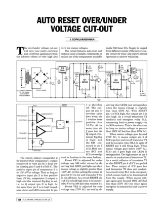
- 1. Auto Reset Over/Under Voltage Cut-Out J. Gopalakrishnan T his over/under voltage cut-out very low mains voltages. inside 555 timer ICs. Supply is tapped will save your costly electrical The circuit features auto reset and from different points of the power sup- and electronic appliances from utilises easily available components. It ply circuit for relay and control circuit the adverse effects of very high and makes use of the comparators available operation to achieve reliability. 7 is therefore serving that LED2 just extinguishes off. The out- when the mains voltage is slightly put (at pin 3) less than 270V AC. With RESET reverses (goes pin 4 of IC2 high, the output pin 3 is low) when pin also high. As a result transistor T2 2 is taken more conducts and energises relay RL1, positive than connecting load to power supply via 1/3 Vcc. At the its N/O contacts. This is the situation same time pin as long as mains voltage is greater 7 goes low (as than 160V AC but less than 270V AC. Q output of in- When mains voltage goes beyond ternal flip-flop 270V AC, it causes output pin 3 of is high) and IC2 to go low and cut-off transistor T2 the ED con- and de-energise relay RL1, in spite of nected to pin 7 RESET pin 4 still being high. When is lit. Both tim- mains voltage goes below 160V AC, ers (IC1 and IC1’s pin 3 goes high and LED1 is IC2) are config- extinguished. The high output at pin 3 The circuit utilises comparator 2 ured to function in the same fashion. results in conduction of transistor T1. for control while comparator 1 output Preset VR1 is adjusted for under As a result collector of transistor T1 (connected to reset pin R) is kept low voltage (say 160 volts) cut-out by ob- as also RESET pin 4 of IC2 are pulled by shorting pins 5 and 6 of 555 IC. The serving that LED1 just lights up when low. Thus output of IC2 goes low positive input pin of comparator 2 is mains voltage is slightly greater than and transistor T2 does not conduct. at 1/3rd of Vcc voltage. Thus as long as 160V AC. At this setting the output at As a result relay RL1 is de-energised, negative input pin 2 is less positive pin 3 of IC1 is low and transistor T1 is which causes load to be disconnected than 1/3 Vcc, comparator 2 output is in cut-off state. As a result RESET pin from the supply. When mains volt- high and the internal flip-flop is set, 4 of IC2 is held high since it is connect- age again goes beyond 160V AC (but i.e. its Q output (pin 3) is high. At ed to Vcc via 100 kilo-ohm resistor R4. less than 270V AC) the relay again the same time pin 7 is in high imped- Preset VR2 is adjusted for over energises to connect the load to power ance state and LED connected to pin voltage (say 270V AC) cut-out by ob- supply. 128 ELECTRONICS PROJECTS Vol. 20