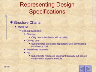
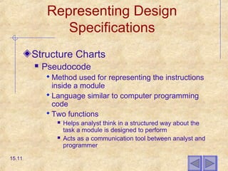
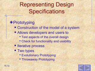
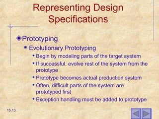
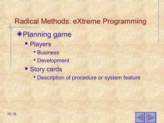
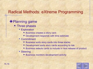
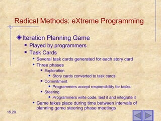
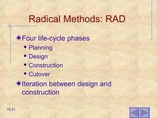
Copyright 2002 Prentice-Hall, Inc.
Modern Systems Analysis
and Design
Third Edition
Jeffrey A. Hoffer
Joey F. George
Joseph S. Valacich
Chapter 15
Finalizing Design
Specifications
15.1
Learning Objectives
Discuss the need for system design
specifications
Define quality requirements and write quality
requirements statements
Read and understand a structure chart
Distinguish between evolutionary and
throwaway prototyping
Explain the role of CASE tools in capturing
design specifications
Demonstrate how design specifications can
be declared for Web-based applications
15.2
Introduction
Need for systems to be developed more
quickly today
The lines between analysis and design and
design and implementation are blurring
 Traditional approaches allowed for a break
between design and implementation
 Other approaches, such as CASE and prototyping,
have caused overlap between the two phases
15.3
The Process of Finalizing
Design Specifications
Less costly to correct and detect errors during
the design phase
Two sets of guidelines
 Writing quality specification statements
 The quality of the specifications themselves
Quality requirement statements
 Correct
 Feasible
 Necessary
 Prioritized
 Unambiguous
 Verifiable15.4
The Process of Finalizing
Design Specifications
Quality requirements
 Completely described
 Do not conflict with other requirements
 Easily changed without adversely affecting
other requirements
 Traceable back to origin
15.5
The Process of Finalizing
Design Specifications
Deliverables and Outcome
 Set of physical design specifications
 Contains detailed specifications for each part of
the system
15.6
Representing Design
Specifications
Traditional Methods
 Pre-CASE
 Documents written natural language and
augmented with graphical models
 Specification documents
 Figure 15-2 shows an example
 Several methods for streamlining
 Computer-based requirements tools
 Prototyping
 Visual development environments
15.7
Representing Design
Specifications
Structure Charts
 Shows how an information system is
organized in hierarchical models
 Shows how parts of a system are related to
one another
 Shows breakdown of a system into
programs and internal structures of
programs written in third and fourth
generation languages
15.8
Representing Design
Specifications
Structure Charts
 Module
 A self-contained component of a system, defined by a
function
 One single coordinating module at the root of structure
chart
 Single point of entry and exit
 Communicate with each other by passing parameters
 Data couple
 A diagrammatic representation of the data exchanged
between two modules in a structure chart
 Flag
 A diagrammatic representation of a message passed
between two modules
15.9
Representing Design
Specifications
Structure Charts
 Module
 Special Symbols
 Diamond
 Only one subordinate will be called
 Curved Line
 Subordinates are called repeatedly until terminating
condition is met
 Predefined modules
 Hat
 Subordinate module is important logically but code is
contained in superior module
15.10
Representing Design
Specifications
Structure Charts
 Pseudocode
 Method used for representing the instructions
inside a module
 Language similar to computer programming
code
 Two functions
 Helps analyst think in a structured way about the
task a module is designed to perform
 Acts as a communication tool between analyst and
programmer
15.11
Representing Design
Specifications
Prototyping
 Construction of the model of a system
 Allows developers and users to
 Test aspects of the overall design
 Check for functionality and usability
 Iterative process
 Two types
 Evolutionary Prototyping
 Throwaway Prototyping
15.12
Representing Design
Specifications
Prototyping
 Evolutionary Prototyping
 Begin by modeling parts of the target system
 If successful, evolve rest of the system from the
prototype
 Prototype becomes actual production system
 Often, difficult parts of the system are
prototyped first
 Exception handling must be added to prototype
15.13
Representing Design
Specifications
Prototyping
 Throwaway Prototyping
 Prototype is not preserved
 Developed quickly to demonstrate unclear
aspect of system design
 Fast, easy to use development environment
aids this approach
15.14
Representing Design
Specifications
Prototyping
 Oracle Designer: An Example
 Transforming and Generating the Database
 Entity-Relationship Diagramming Tool
 Database Design Transformer Tool
 Server Model Diagram
 End Result
 Generation of Data Definition Language (DDL)
scripts
 Create database by running scripts
15.15
Representing Design
Specifications
Prototyping
 Oracle Designer: An Example
 Transforming and Generating Software
Modules
 Data Flow Diagram
 Functional Hierarchy Diagram
 Application Design Transformer
 Transforms diagrams into software modules
which can be used to generate forms or reports
 Generate form or report in Design Editor
15.16
Radical Methods: eXtreme Programming
Short cycles
Incremental planning approach
Automated tests
Utilizes two-person programming team
Planning, analysis, design and construction
are fused together into one phase
Requirements and specifications are uniquely
captured
15.17
Radical Methods: eXtreme Programming
Planning game
 Players
 Business
 Development
 Story cards
 Description of procedure or system feature
15.18
Radical Methods: eXtreme Programming
Planning game
 Three phases
 Exploration
 Business creates a story card
 Development responds with time estimate
 Commitment
 Business sorts story cards into three stacks
 Development sorts story cards according to risk
 Business selects cards to include in next release of product
 Steering
 Business monitors development activity
15.19
Radical Methods: eXtreme Programming
Iteration Planning Game
 Played by programmers
 Task Cards
 Several task cards generated for each story card
 Three phases
 Exploration
 Story cards converted to task cards
 Commitment
 Programmers accept responsibility for tasks
 Steering
 Programmers write code, test it and integrate it
 Game takes place during time between intervals of
planning game steering phase meetings
15.20
Radical Methods: RAD
Four life-cycle phases
 Planning
 Design
 Construction
 Cutover
Iteration between design and
construction
15.21
Electronic Commerce
Application
Microsoft FrontPage used to build
throwaway prototype
Template based HTML
15.22
Summary
Types of Design Specifications
 Written document augmented by various
diagrams
 Structure chart
 Computer-based requirements
management tool
 Prototypes
 Throwaway versus Evolutionary
15.23
Summary
Radical Methods
 eXtreme Programming
 RAD
Electronic Commerce Application
 Throwaway prototyping
15.24

Chapter15 finalizing design specifications

  • 1.
    Copyright 2002 Prentice-Hall,Inc. Modern Systems Analysis and Design Third Edition Jeffrey A. Hoffer Joey F. George Joseph S. Valacich Chapter 15 Finalizing Design Specifications 15.1
  • 2.
    Learning Objectives Discuss theneed for system design specifications Define quality requirements and write quality requirements statements Read and understand a structure chart Distinguish between evolutionary and throwaway prototyping Explain the role of CASE tools in capturing design specifications Demonstrate how design specifications can be declared for Web-based applications 15.2
  • 3.
    Introduction Need for systemsto be developed more quickly today The lines between analysis and design and design and implementation are blurring  Traditional approaches allowed for a break between design and implementation  Other approaches, such as CASE and prototyping, have caused overlap between the two phases 15.3
  • 4.
    The Process ofFinalizing Design Specifications Less costly to correct and detect errors during the design phase Two sets of guidelines  Writing quality specification statements  The quality of the specifications themselves Quality requirement statements  Correct  Feasible  Necessary  Prioritized  Unambiguous  Verifiable15.4
  • 5.
    The Process ofFinalizing Design Specifications Quality requirements  Completely described  Do not conflict with other requirements  Easily changed without adversely affecting other requirements  Traceable back to origin 15.5
  • 6.
    The Process ofFinalizing Design Specifications Deliverables and Outcome  Set of physical design specifications  Contains detailed specifications for each part of the system 15.6
  • 7.
    Representing Design Specifications Traditional Methods Pre-CASE  Documents written natural language and augmented with graphical models  Specification documents  Figure 15-2 shows an example  Several methods for streamlining  Computer-based requirements tools  Prototyping  Visual development environments 15.7
  • 8.
    Representing Design Specifications Structure Charts Shows how an information system is organized in hierarchical models  Shows how parts of a system are related to one another  Shows breakdown of a system into programs and internal structures of programs written in third and fourth generation languages 15.8
  • 9.
    Representing Design Specifications Structure Charts Module  A self-contained component of a system, defined by a function  One single coordinating module at the root of structure chart  Single point of entry and exit  Communicate with each other by passing parameters  Data couple  A diagrammatic representation of the data exchanged between two modules in a structure chart  Flag  A diagrammatic representation of a message passed between two modules 15.9
  • 10.
    Representing Design Specifications Structure Charts Module  Special Symbols  Diamond  Only one subordinate will be called  Curved Line  Subordinates are called repeatedly until terminating condition is met  Predefined modules  Hat  Subordinate module is important logically but code is contained in superior module 15.10
  • 11.
    Representing Design Specifications Structure Charts Pseudocode  Method used for representing the instructions inside a module  Language similar to computer programming code  Two functions  Helps analyst think in a structured way about the task a module is designed to perform  Acts as a communication tool between analyst and programmer 15.11
  • 12.
    Representing Design Specifications Prototyping  Constructionof the model of a system  Allows developers and users to  Test aspects of the overall design  Check for functionality and usability  Iterative process  Two types  Evolutionary Prototyping  Throwaway Prototyping 15.12
  • 13.
    Representing Design Specifications Prototyping  EvolutionaryPrototyping  Begin by modeling parts of the target system  If successful, evolve rest of the system from the prototype  Prototype becomes actual production system  Often, difficult parts of the system are prototyped first  Exception handling must be added to prototype 15.13
  • 14.
    Representing Design Specifications Prototyping  ThrowawayPrototyping  Prototype is not preserved  Developed quickly to demonstrate unclear aspect of system design  Fast, easy to use development environment aids this approach 15.14
  • 15.
    Representing Design Specifications Prototyping  OracleDesigner: An Example  Transforming and Generating the Database  Entity-Relationship Diagramming Tool  Database Design Transformer Tool  Server Model Diagram  End Result  Generation of Data Definition Language (DDL) scripts  Create database by running scripts 15.15
  • 16.
    Representing Design Specifications Prototyping  OracleDesigner: An Example  Transforming and Generating Software Modules  Data Flow Diagram  Functional Hierarchy Diagram  Application Design Transformer  Transforms diagrams into software modules which can be used to generate forms or reports  Generate form or report in Design Editor 15.16
  • 17.
    Radical Methods: eXtremeProgramming Short cycles Incremental planning approach Automated tests Utilizes two-person programming team Planning, analysis, design and construction are fused together into one phase Requirements and specifications are uniquely captured 15.17
  • 18.
    Radical Methods: eXtremeProgramming Planning game  Players  Business  Development  Story cards  Description of procedure or system feature 15.18
  • 19.
    Radical Methods: eXtremeProgramming Planning game  Three phases  Exploration  Business creates a story card  Development responds with time estimate  Commitment  Business sorts story cards into three stacks  Development sorts story cards according to risk  Business selects cards to include in next release of product  Steering  Business monitors development activity 15.19
  • 20.
    Radical Methods: eXtremeProgramming Iteration Planning Game  Played by programmers  Task Cards  Several task cards generated for each story card  Three phases  Exploration  Story cards converted to task cards  Commitment  Programmers accept responsibility for tasks  Steering  Programmers write code, test it and integrate it  Game takes place during time between intervals of planning game steering phase meetings 15.20
  • 21.
    Radical Methods: RAD Fourlife-cycle phases  Planning  Design  Construction  Cutover Iteration between design and construction 15.21
  • 22.
    Electronic Commerce Application Microsoft FrontPageused to build throwaway prototype Template based HTML 15.22
  • 23.
    Summary Types of DesignSpecifications  Written document augmented by various diagrams  Structure chart  Computer-based requirements management tool  Prototypes  Throwaway versus Evolutionary 15.23
  • 24.
    Summary Radical Methods  eXtremeProgramming  RAD Electronic Commerce Application  Throwaway prototyping 15.24