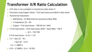
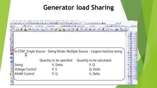
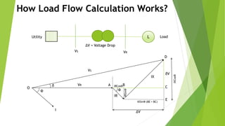
Chapter 2- Part two
Load flow analysis
Computer Application in Power Systems
Chapter Two :- Load flow Analysis
Golis University
Abdiaziz Hussein
Transformer X/R Ratio Calculation
 X/R ratio is not available in transformer data sheet ??
 Calculate using Copper losses / Full load losses provided in data sheet
 Transformer Datasheet:
 MVA Rating = 25 MVA (shall be assumed as Base MVA)
 % Impedance (Z) = 8%
 Copper / Full load losses = 100 kW (0.1 MW)
 % Full load losses = (Full load losses (MW) / Base MVA) * 100 %
= (0.1 / 25)*100
% Full load losses = 0.4 % = % R
 % X = Sqrt (Z2 – R2)
= Sqrt (82 – 0.42)
% X = 7.9899 %
 X/R = (7.9899) / 0.4 = 19.974
Transformer MVA Sizing
 Based on ANSI C57 and IEC 60076 standards
 Considers multiple cooling stages and transformer types
(3-phase & 1-phase)
 Considers altitude correction factors
 Considers temperature correction factors
 Load variation
 Considers short-circuit impedance requirements
 Use connected load or operating load
Transformer MVA Page in ETAP
Temperature Correction
 Ambient temperature in degree Celsius
 For air cooled transformers use the air ambient temperature
 For water cooled transformers use the water temperature
 Based on C57.92-1981 and IEC 76-2
Altitude Correction
 Derate the transformer capacity based on altitude of the installation
 Derating starts above 1000 m or 3300 ft
 Based on C57.92-1981 and IEC 76-2
Load Variation
 Growth Factor
Allowance for future load growth
 Load Factor
The ratio of the average load to the peak load over a
designated period of time
 Load Factor = 100 x ( kWi x Ti ) / ( kWp x Tt )%
 Load Factor = 100 x E / ( kWi x Tt )%
Short Circuit Impedance
Connected / Operating Load
 Connected Load
 Determine the radial load connected to the transformer secondary
 Can include spare loads for conservative results
 Operating Load
 PowerStation’s load flow program determines the power flow through
the transformer
 Automatically updated in the transformer required MVAfield (load
flow study case info page option)
 Can determine loading in radial or looped systems
Sizing Results & Automatic Update
 Sizing results include MVAand % Z for
 Required Size (Actual calculated Size)
 Next Standard Larger Size
 Next Standard Smaller Size
 Automatically Update the calculated rated MVA, Max MVA and % Z into the
Rating page of the transformer
Generator load Sharing
Load Flow Analysis Calculation
(Comparing Hand Calculations with ETAP Results)
How Load Flow Calculation Works?
O
VS
I
VR
IR
IX
δ
Ф Ф
A
D
C
E
∆V
δV
IRCosФB
IRSinФ
IXSinФ (BE = BC)
IXCosФ
L
VS VR
Utility
∆V = Voltage Drop
Load
O
VS
I
VR
IR
IX
δ
Ф Ф
A
How Load Flow Calculation Works?
D
C
E
∆V
δV
IRCosФB
OD = VS, OA = VR
OD2 = OC2 + CD2
OD2 = (OA+AB+BC)2 + (DE-CE)2
AB = IR COSФ, BC = IX SINФ
DE = IX COSФ, CE = IR SINФ
VS2 = (VR + IR COSФ + IXSINФ)2 + (IX COSФ – IR SINФ)2
= (VR + (R*P + X*Q)/VR)2 + (X*P – R*Q)/VR)2
= √{(VR + (R*P + X*Q)/VR)2 + (X*P – R*Q)/VR)2}
= CD / OC = (DE – CE) / (OA + AB + BC)
= (IX COSФ - IR SINФ) / (VR + IR COSФ + IX SINФ)
= ((X*P – R*Q)/VR) / (VR + (R*P + X*Q)/VR)
= ATAN [((X*P – R*Q)/VR) / (VR + (R*P + X*Q)/VR)] Radian
VS
T
ANδ
δ
IRSinФ
IXSinФ (BE = BC)
IXCosФ
How Load Flow Calculation Works?
Grid Data
Grid Voltage = 33kV
Bus Data
Bus Voltage = 33kV
Transformer Data
Voltage Rating – 33/11.55 kV
MVA Rating – 15 MVA
% Impedance – 10%
X/R Ratio – 18.6
Load Data
Voltage Rating – 11 kV
, MVA Rating – 12 MVA
Motor Load - 80%, Static Load – 20%
Power Factor – 80%

Chapter two Part two.pptx

  • 1.
    Chapter 2- Parttwo Load flow analysis Computer Application in Power Systems Chapter Two :- Load flow Analysis Golis University Abdiaziz Hussein
  • 2.
  • 3.
    Transformer X/R RatioCalculation  X/R ratio is not available in transformer data sheet ??  Calculate using Copper losses / Full load losses provided in data sheet  Transformer Datasheet:  MVA Rating = 25 MVA (shall be assumed as Base MVA)  % Impedance (Z) = 8%  Copper / Full load losses = 100 kW (0.1 MW)  % Full load losses = (Full load losses (MW) / Base MVA) * 100 % = (0.1 / 25)*100 % Full load losses = 0.4 % = % R  % X = Sqrt (Z2 – R2) = Sqrt (82 – 0.42) % X = 7.9899 %  X/R = (7.9899) / 0.4 = 19.974
  • 4.
  • 5.
    Transformer MVA Sizing Based on ANSI C57 and IEC 60076 standards  Considers multiple cooling stages and transformer types (3-phase & 1-phase)  Considers altitude correction factors  Considers temperature correction factors  Load variation  Considers short-circuit impedance requirements  Use connected load or operating load
  • 6.
  • 7.
    Temperature Correction  Ambienttemperature in degree Celsius  For air cooled transformers use the air ambient temperature  For water cooled transformers use the water temperature  Based on C57.92-1981 and IEC 76-2
  • 8.
    Altitude Correction  Deratethe transformer capacity based on altitude of the installation  Derating starts above 1000 m or 3300 ft  Based on C57.92-1981 and IEC 76-2
  • 9.
    Load Variation  GrowthFactor Allowance for future load growth  Load Factor The ratio of the average load to the peak load over a designated period of time  Load Factor = 100 x ( kWi x Ti ) / ( kWp x Tt )%  Load Factor = 100 x E / ( kWi x Tt )%
  • 10.
  • 11.
    Connected / OperatingLoad  Connected Load  Determine the radial load connected to the transformer secondary  Can include spare loads for conservative results  Operating Load  PowerStation’s load flow program determines the power flow through the transformer  Automatically updated in the transformer required MVAfield (load flow study case info page option)  Can determine loading in radial or looped systems
  • 12.
    Sizing Results &Automatic Update  Sizing results include MVAand % Z for  Required Size (Actual calculated Size)  Next Standard Larger Size  Next Standard Smaller Size  Automatically Update the calculated rated MVA, Max MVA and % Z into the Rating page of the transformer
  • 13.
  • 14.
  • 16.
    Load Flow AnalysisCalculation (Comparing Hand Calculations with ETAP Results)
  • 17.
    How Load FlowCalculation Works? O VS I VR IR IX δ Ф Ф A D C E ∆V δV IRCosФB IRSinФ IXSinФ (BE = BC) IXCosФ L VS VR Utility ∆V = Voltage Drop Load
  • 18.
    O VS I VR IR IX δ Ф Ф A How LoadFlow Calculation Works? D C E ∆V δV IRCosФB OD = VS, OA = VR OD2 = OC2 + CD2 OD2 = (OA+AB+BC)2 + (DE-CE)2 AB = IR COSФ, BC = IX SINФ DE = IX COSФ, CE = IR SINФ VS2 = (VR + IR COSФ + IXSINФ)2 + (IX COSФ – IR SINФ)2 = (VR + (R*P + X*Q)/VR)2 + (X*P – R*Q)/VR)2 = √{(VR + (R*P + X*Q)/VR)2 + (X*P – R*Q)/VR)2} = CD / OC = (DE – CE) / (OA + AB + BC) = (IX COSФ - IR SINФ) / (VR + IR COSФ + IX SINФ) = ((X*P – R*Q)/VR) / (VR + (R*P + X*Q)/VR) = ATAN [((X*P – R*Q)/VR) / (VR + (R*P + X*Q)/VR)] Radian VS T ANδ δ IRSinФ IXSinФ (BE = BC) IXCosФ
  • 19.
    How Load FlowCalculation Works? Grid Data Grid Voltage = 33kV Bus Data Bus Voltage = 33kV Transformer Data Voltage Rating – 33/11.55 kV MVA Rating – 15 MVA % Impedance – 10% X/R Ratio – 18.6 Load Data Voltage Rating – 11 kV , MVA Rating – 12 MVA Motor Load - 80%, Static Load – 20% Power Factor – 80%