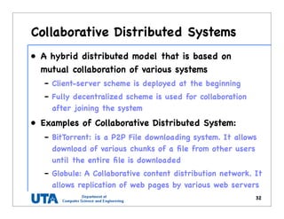
Download as PDF, PPTX

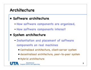
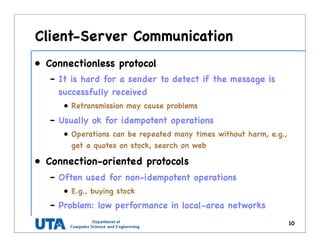
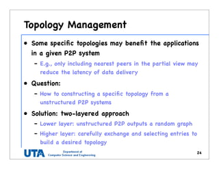
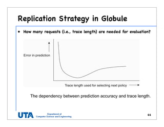
![Content Addressable Network (1)
17
•2-dim space [0,1] x [0,1] is
divided among 6 nodes
•Each node has an
associated region
•Every data item in CAN
will be assigned a unique
point in space
•That node is responsible
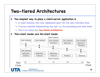
for that data element.](https://image.slidesharecdn.com/2-architecture-161015054614/85/chapter-2-architecture-17-320.jpg)
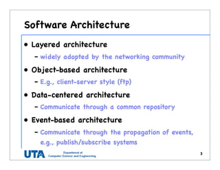
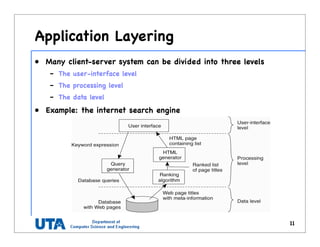
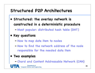
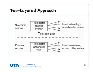
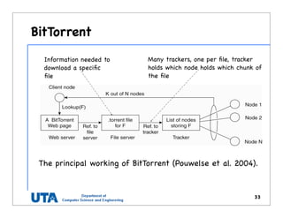
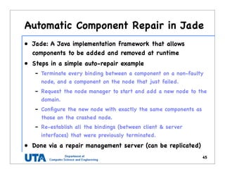
![Random Graph
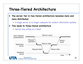
• Given N nodes, we build
a random graph by
– having an edge
between any two nodes
at a probability p
• The random graph
theory is to answer
– what value should p
have such that it is
“almost certainly true”
that the graph is fully
connected
20
ors of the DSN. For ex-
eep-deprivation attack”
f the sensor nodes with
s by excessive commu-
pture typically requires
[7, 13, 14] be used to
hysical sensor manipu-
e sensor’s key ring and
ion3
. For some sensor
pt a node’s key ring in
can be very fast.
tion via sensor-node shield-
nodes, we note that our
ust than those based on
private sharing of keys
s against captured un-
mission key scheme, all
ed, whereas in the pair-
ks to the captured un-
contrast, in our scheme
ng are obtained, which
1000 2000 3000 4000 5000 6000 7000 8000 9000 10000
10
12
14
16
18
20
22
24
n (number of nodes)
Pr=0.99
Pr=0.999
Pr=0.9999
Pr=0.99999
Pr=0.999999
d(expecteddegreeofnode)
Figure 1: Expected degree of node vs. numbe
nodes, where Pc = Pr[G(n, p) is connected]](https://image.slidesharecdn.com/2-architecture-161015054614/85/chapter-2-architecture-20-320.jpg)
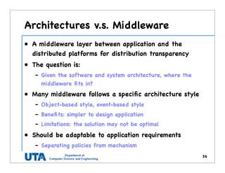
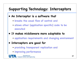
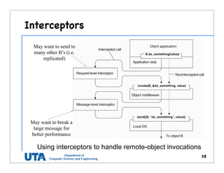
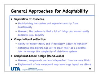

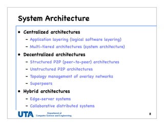
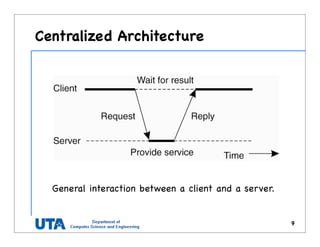
This document discusses various distributed system architectures including centralized, decentralized, and hybrid architectures. It covers software architectures like layered architectures, object-based architectures, and event-based architectures. It also discusses system architectures including client-server, peer-to-peer, structured P2P (like Chord and CAN), unstructured P2P, and hybrid architectures combining centralized and decentralized elements like edge server systems and collaborative distributed systems. Middleware is described as sitting between applications and distributed platforms to provide distribution transparency. Adaptability techniques like interceptors, separation of concerns, reflection, and feedback control loops are also summarized.