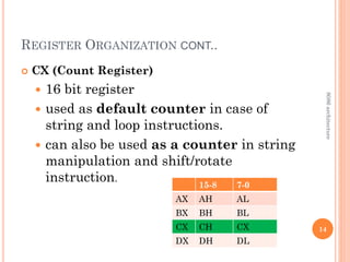
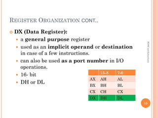
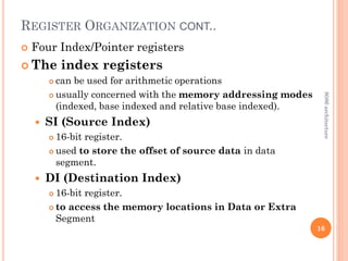
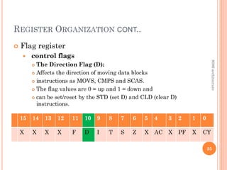
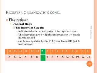
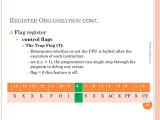
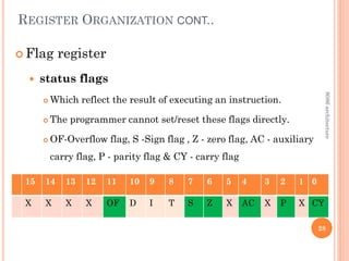
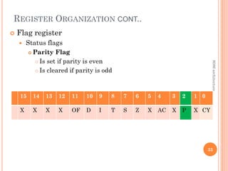
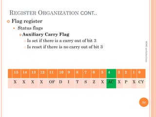
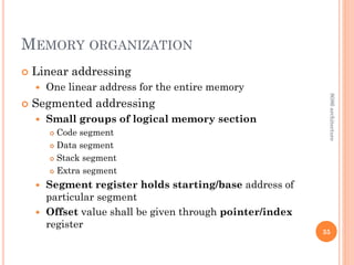
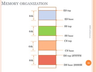
CHAPTER 2
THE 8086 MICROPROCESSOR ARCHITECTURE
LECTURE 1
CONTENTS
2
 8086 architecture
 General Information
 Functional Diagram
 Register Organization
 Memory segmentation
 Memory addresses
8086
architecture
FEATURES 8086
 16-bit Microprocessor
 It’s ALU, internal registers works with 16 bit
binary word.
 20 bit address bus
 can address up to 220
= 1 MB memory locations.
 AD0- AD15 and A16 – A19.
 16 bit data bus.
 It can read or write data to a memory/port either 16
bits or 8 bit at a time.
 It can support up to 216 = 64K I/O ports.
 Fourteen 16 -bit registers 3
8086
architecture
FEATURES 8086 CONT..
 Frequency range : 6-10 MHz
 Pre-fetch up to 6 instructions bytes from
memory and queues
 It requires +5V power supply.
 A 40 pin dual in line package.
 Two modes
 Minimum mode
 Maximum mode
 Support multiprogramming 4
8086
architecture
BLOCK DIAGRAM
5
8086
architecture
BLOCK DIAGRAM CONT..
 Two Blocks
 Bus Interface Unit(BUI)
 Execution Unit (EU)
 Bus Interface Unit(BUI)
 Contains Instruction queue, Segment registers,
Instruction pointer, Address adder.
 Performs all bus operations
 Execution Unit (EU)
 Contains Control circuitry, Instruction decoder, ALU,
Pointer and Index register, Flag register and general
purpose register
 Executes instructions from the instruction queue. 6
8086
architecture
BLOCK DIAGRAM CONT..
 Bus Interface Unit(BUI)
 Has 16 bit bidirectional data bus
 Has 20 bit address bus.
 responsible for performing all external bus
operations.
 Instruction fetch and Instruction queuing
 Operand fetch and storage
 Address relocation and Bus control.
 Has instruction stream queue to implement pipeline
architecture.
 prefetching instructions are held in its FIFO queue.
 With its 16 bit data bus, the BIU fetches two
instruction bytes in a single memory cycle. 7
8086
architecture
BLOCK DIAGRAM CONT..
 Bus Interface Unit(BUI)
 Contains a dedicated adder
 used to generate the 20 bit physical address
 This address is formed by adding an appended 16 bit
segment address and a 16 bit offset address.
 example:
 The physical address of the next instruction to be fetched
is formed by combining the current contents of the code
segment CS register and the current contents of the
instruction pointer IP register.
 The BIU is also responsible for generating bus
control signals such as those for memory read or
write and I/O read or write.
8
8086
architecture
BLOCK DIAGRAM CONT..
 Execution Unit (EU)
 responsible for decoding and executing all
instructions.
 extracts instructions from the top of the
queue in the BIU, decodes them, generates
operands if necessary, passes them to the
BIU
 tests the status and control flags and
updates them
 If the queue is empty, the EU waits for the
next instruction byte to be fetched and shifted
to top of the queue.
9
8086
architecture
REGISTER ORGANIZATION
 Fourteen registers that are accessible to
the programmer.
 It is divided into four groups.
 Four General purpose registers
 Four Index/Pointer registers
 Four Segment registers
 Two Other registers 10
8086
architecture
REGISTER ORGANIZATION CONT..
 Four General purpose registers
 Accumulator -AX
 Base -BX
 Count -CX
 Data -DX
 16- bit each
11
15-0 15-8 7-0
AX AH AL
BX BH BL
CX CH CX
DX DH DL
8086
architecture
REGISTER ORGANIZATION CONT..
 AX (Accumulator):
 AX is used as 16-bit accumulator.
 The lower 8-bits of AX are AL
 The higher 8-bits are AH.
 AL can be used as an 8-bit accumulator.
 Used in arithmetic, logic and data transfer
operations.
 For multiplication and division operations,
one of the numbers must be placed in AX
or AL.
12
15-8 7-0
AX AH AL
BX BH BL
CX CH CX
DX DH DL
8086
architecture
REGISTER ORGANIZATION CONT..
 BX (Base Register):
 16 bit register,
BL indicates the lower 8-bits of BX and
BH indicates the higher 8-bits of BX.
 Used as address register to form physical
address in case of certain addressing modes
example: indexed and register indirect.
13
15-8 7-0
AX AH AL
BX BH BL
CX CH CX
DX DH DL
8086
architecture
REGISTER ORGANIZATION CONT..
 CX (Count Register)
 16 bit register
 used as default counter in case of
string and loop instructions.
 can also be used as a counter in string
manipulation and shift/rotate
instruction.
14
15-8 7-0
AX AH AL
BX BH BL
CX CH CX
DX DH DL
8086
architecture
REGISTER ORGANIZATION CONT..
 DX (Data Register):
 a general purpose register
 used as an implicit operand or destination
in case of a few instructions.
 can also be used as a port number in I/O
operations.
 16- bit
 DH or DL
15
15-8 7-0
AX AH AL
BX BH BL
CX CH CX
DX DH DL
8086
architecture
REGISTER ORGANIZATION CONT..
 Four Index/Pointer registers
 The index registers
 can be used for arithmetic operations
 usually concerned with the memory addressing modes
(indexed, base indexed and relative base indexed).
 SI (Source Index)
 16-bit register.
 used to store the offset of source data in data
segment.
 DI (Destination Index)
 16-bit register.
 to access the memory locations in Data or Extra
Segment
16
8086
architecture
REGISTER ORGANIZATION CONT..
 Four Index/Pointer registers
 Pointer Registers
 contains the offset of data(variables, labels) and
instructions from their base segments
 8086 microprocessor contains three pointer
registers.
 SP (Stack Pointer):
 points the program stack that means SP stores the base
address of the Stack Segment.
 BP (Base Pointer):
 points stack segment.
 can use BP to access data in the other segments also.
17
8086
architecture
REGISTER ORGANIZATION CONT..
Four Segment registers to access 1
megabyte of memory
 CS (Code Segment):
a 16-bit register (64Kb)
where the executable program is stored.
CS register cannot be changed directly.
The CS register is automatically updated
during far jump, far call and far return
instructions.
18
8086
architecture
REGISTER ORGANIZATION CONT..
 Four Segment registers to access 1 megabyte of
memory
 Stack segment (SS)
a 16-bit register
used for addressing stack segment of the
memory (64kb) where stack data is stored.
SS register can be changed directly using
POP instruction.
19
8086
architecture
REGISTER ORGANIZATION CONT..
 Four Segment registers to access 1 megabyte of
memory
 Data segment (DS)
a 16-bit register that points the data
segment of the memory (64kb)
where the program data is stored.
can be changed directly using POP and LDS
instructions.
20
8086
architecture
REGISTER ORGANIZATION CONT..
 Four Segment registers to access 1 megabyte of
memory
 Extra segment (ES):
a 16-bit register that also points the data
segment of the memory (64kb)
where the program data is stored.
ES register can be changed directly using
POP and LES instructions.
21
8086
architecture
REGISTER ORGANIZATION CONT..
Two Other registers
 Instruction pointer
 Flag register
 IP (Instruction Pointer):
holds the address of the next instruction to
be fetched from memory.
It contains the offset of the next word of
instruction code instead of its actual address
22
8086
architecture
REGISTER ORGANIZATION CONT..
 Flag register
 Indicates some condition produced following instruction
execution
 16 bit register only nine of them active
 F-Overflow flag, D – Directional flag, I- Interrupt flag, T- Trap flag,
S -Sign flag , Z - zero flag, AC - auxiliary carry flag, P - parity flag &
CY - carry flag
23
15 14 13 12 11 10 9 8 7 6 5 4 3 2 1 0
X X X X F D I T S Z X AC X P X CY
8086
architecture
REGISTER ORGANIZATION CONT..
 Flag register
 control flags
 Enable or disable certain CPU operations.
 The programmer can set/reset
 D-Directional flag, I- Interrupt flag, T- Trap flag,
24
15 14 13 12 11 10 9 8 7 6 5 4 3 2 1 0
X X X X OF D I T S Z X AC X P X CY
8086
architecture
REGISTER ORGANIZATION CONT..
 Flag register
 control flags
 The Direction Flag (D):
 Affects the direction of moving data blocks
 instructions as MOVS, CMPS and SCAS.
 The flag values are 0 = up and 1 = down and
 can be set/reset by the STD (set D) and CLD (clear D)
instructions.
25
15 14 13 12 11 10 9 8 7 6 5 4 3 2 1 0
X X X X F D I T S Z X AC X PF X CY
8086
architecture
REGISTER ORGANIZATION CONT..
 Flag register
 control flags
 The Interrupt Flag (I):
 indicates whether or not system interrupts can occur.
 The flag values are 0 = disable interrupts or 1 = enable
interrupts and
 can be manipulated by the CLI (clear I) and STI (set I)
instructions.
26
15 14 13 12 11 10 9 8 7 6 5 4 3 2 1 0
X X X X F D I T S Z X AC X PF X CY
8086
architecture
REGISTER ORGANIZATION CONT..
 Flag register
 control flags
 The Trap Flag (T):
 Determines whether or not the CPU is halted after the
execution of each instruction.
 set (i.e. = 1), the programmer can single step through his
program to debug any errors.
 flag = 0 this feature is off.
27
15 14 13 12 11 10 9 8 7 6 5 4 3 2 1 0
X X X X F D I T S Z X AC X PF X CY
8086
architecture
REGISTER ORGANIZATION CONT..
 Flag register
 status flags
 Which reflect the result of executing an instruction.
 The programmer cannot set/reset these flags directly.
 OF-Overflow flag, S -Sign flag , Z - zero flag, AC - auxiliary
carry flag, P - parity flag & CY - carry flag
28
15 14 13 12 11 10 9 8 7 6 5 4 3 2 1 0
X X X X OF D I T S Z X AC X P X CY
8086
architecture
REGISTER ORGANIZATION CONT..
 Flag register
 Status flags
 Overflow flag bit
 This flag is set when the result of a signed
arithmetic operation is too large to fit in the
destination register
 Overflow can occur when adding two numbers with
the same sign (i.e. both positive or both negative).
 A value of 1 = overflow and 0 = no overflow
29
15 14 13 12 11 10 9 8 7 6 5 4 3 2 1 0
X X X X F D I T S Z X AC X PF X CY
8086
architecture
REGISTER ORGANIZATION CONT..
 Flag register
 Status flags
 Sign flag bit
 Used for indicating the sign of the data in the
accumulator
 The sign flag is set if negative (1 – negative)
 The sign flag is reset if positive (0 –positive)
30
15 14 13 12 11 10 9 8 7 6 5 4 3 2 1 0
X X X X F D I T S Z X AC X PF X CY
8086
architecture
REGISTER ORGANIZATION CONT..
 Flag register
 Status flags
 Zero Flag
 Is set if result obtained after an operation is 0
 Is set following an increment or decrement
operation of that register
31
8086
architecture
15 14 13 12 11 10 9 8 7 6 5 4 3 2 1 0
X X X X OF D I T S Z X AC X P X CY
REGISTER ORGANIZATION CONT..
 Flag register
 Status flags
 Carry Flag
 Is set if there is a carry or borrow from arithmetic
operation
 1011 0101
+ 0110 1100
---------------
Carry 1 0010 0001
32
8086
architecture
15 14 13 12 11 10 9 8 7 6 5 4 3 2 1 0
X X X X OF D I T S Z X AC X P X CY
REGISTER ORGANIZATION CONT..
 Flag register
 Status flags
 Parity Flag
 Is set if parity is even
 Is cleared if parity is odd
33
8086
architecture
15 14 13 12 11 10 9 8 7 6 5 4 3 2 1 0
X X X X OF D I T S Z X AC X P X CY
REGISTER ORGANIZATION CONT..
 Flag register
 Status flags
 Auxiliary Carry Flag
 Is set if there is a carry out of bit 3
 Is reset if there is no carry out of bit 3
34
8086
architecture
15 14 13 12 11 10 9 8 7 6 5 4 3 2 1 0
X X X X OF D I T S Z X AC X P X CY
MEMORY ORGANIZATION
 Linear addressing
 One linear address for the entire memory
 Segmented addressing
 Small groups of logical memory section
 Code segment
 Data segment
 Stack segment
 Extra segment
 Segment register holds starting/base address of
particular segment
 Offset value shall be given through pointer/index
register
35
8086
architecture
MEMORY ORGANIZATION
36
DS base 20000H
DS top 2FFFFH
CS base
CS top
SS base
SS top
ES base
ES top
64k
64k
64k
64k
8086
architecture
DEFAULT REGISTER VALUES
37
Type of memory
reference
Default
segment
Alternate
segments
offset
Instruction fetch CS None IP
Stack operation SS None SP, BP
General data DS CS, ES, SS Effective address
String source DS CS, ES, SS SI
String destination ES None DI
BX, as pointer DS CS, ES, SS Effective address
BP, as pointer SS CS, ES, SS Effective address
8086
architecture

chapter 2 8086 architecture L11_2024.pdf

  • 1.
    CHAPTER 2 THE 8086MICROPROCESSOR ARCHITECTURE LECTURE 1
  • 2.
    CONTENTS 2  8086 architecture General Information  Functional Diagram  Register Organization  Memory segmentation  Memory addresses 8086 architecture
  • 3.
    FEATURES 8086  16-bitMicroprocessor  It’s ALU, internal registers works with 16 bit binary word.  20 bit address bus  can address up to 220 = 1 MB memory locations.  AD0- AD15 and A16 – A19.  16 bit data bus.  It can read or write data to a memory/port either 16 bits or 8 bit at a time.  It can support up to 216 = 64K I/O ports.  Fourteen 16 -bit registers 3 8086 architecture
  • 4.
    FEATURES 8086 CONT.. Frequency range : 6-10 MHz  Pre-fetch up to 6 instructions bytes from memory and queues  It requires +5V power supply.  A 40 pin dual in line package.  Two modes  Minimum mode  Maximum mode  Support multiprogramming 4 8086 architecture
  • 5.
  • 6.
    BLOCK DIAGRAM CONT.. Two Blocks  Bus Interface Unit(BUI)  Execution Unit (EU)  Bus Interface Unit(BUI)  Contains Instruction queue, Segment registers, Instruction pointer, Address adder.  Performs all bus operations  Execution Unit (EU)  Contains Control circuitry, Instruction decoder, ALU, Pointer and Index register, Flag register and general purpose register  Executes instructions from the instruction queue. 6 8086 architecture
  • 7.
    BLOCK DIAGRAM CONT.. Bus Interface Unit(BUI)  Has 16 bit bidirectional data bus  Has 20 bit address bus.  responsible for performing all external bus operations.  Instruction fetch and Instruction queuing  Operand fetch and storage  Address relocation and Bus control.  Has instruction stream queue to implement pipeline architecture.  prefetching instructions are held in its FIFO queue.  With its 16 bit data bus, the BIU fetches two instruction bytes in a single memory cycle. 7 8086 architecture
  • 8.
    BLOCK DIAGRAM CONT.. Bus Interface Unit(BUI)  Contains a dedicated adder  used to generate the 20 bit physical address  This address is formed by adding an appended 16 bit segment address and a 16 bit offset address.  example:  The physical address of the next instruction to be fetched is formed by combining the current contents of the code segment CS register and the current contents of the instruction pointer IP register.  The BIU is also responsible for generating bus control signals such as those for memory read or write and I/O read or write. 8 8086 architecture
  • 9.
    BLOCK DIAGRAM CONT.. Execution Unit (EU)  responsible for decoding and executing all instructions.  extracts instructions from the top of the queue in the BIU, decodes them, generates operands if necessary, passes them to the BIU  tests the status and control flags and updates them  If the queue is empty, the EU waits for the next instruction byte to be fetched and shifted to top of the queue. 9 8086 architecture
  • 10.
    REGISTER ORGANIZATION  Fourteenregisters that are accessible to the programmer.  It is divided into four groups.  Four General purpose registers  Four Index/Pointer registers  Four Segment registers  Two Other registers 10 8086 architecture
  • 11.
    REGISTER ORGANIZATION CONT.. Four General purpose registers  Accumulator -AX  Base -BX  Count -CX  Data -DX  16- bit each 11 15-0 15-8 7-0 AX AH AL BX BH BL CX CH CX DX DH DL 8086 architecture
  • 12.
    REGISTER ORGANIZATION CONT.. AX (Accumulator):  AX is used as 16-bit accumulator.  The lower 8-bits of AX are AL  The higher 8-bits are AH.  AL can be used as an 8-bit accumulator.  Used in arithmetic, logic and data transfer operations.  For multiplication and division operations, one of the numbers must be placed in AX or AL. 12 15-8 7-0 AX AH AL BX BH BL CX CH CX DX DH DL 8086 architecture
  • 13.
    REGISTER ORGANIZATION CONT.. BX (Base Register):  16 bit register, BL indicates the lower 8-bits of BX and BH indicates the higher 8-bits of BX.  Used as address register to form physical address in case of certain addressing modes example: indexed and register indirect. 13 15-8 7-0 AX AH AL BX BH BL CX CH CX DX DH DL 8086 architecture
  • 14.
    REGISTER ORGANIZATION CONT.. CX (Count Register)  16 bit register  used as default counter in case of string and loop instructions.  can also be used as a counter in string manipulation and shift/rotate instruction. 14 15-8 7-0 AX AH AL BX BH BL CX CH CX DX DH DL 8086 architecture
  • 15.
    REGISTER ORGANIZATION CONT.. DX (Data Register):  a general purpose register  used as an implicit operand or destination in case of a few instructions.  can also be used as a port number in I/O operations.  16- bit  DH or DL 15 15-8 7-0 AX AH AL BX BH BL CX CH CX DX DH DL 8086 architecture
  • 16.
    REGISTER ORGANIZATION CONT.. Four Index/Pointer registers  The index registers  can be used for arithmetic operations  usually concerned with the memory addressing modes (indexed, base indexed and relative base indexed).  SI (Source Index)  16-bit register.  used to store the offset of source data in data segment.  DI (Destination Index)  16-bit register.  to access the memory locations in Data or Extra Segment 16 8086 architecture
  • 17.
    REGISTER ORGANIZATION CONT.. Four Index/Pointer registers  Pointer Registers  contains the offset of data(variables, labels) and instructions from their base segments  8086 microprocessor contains three pointer registers.  SP (Stack Pointer):  points the program stack that means SP stores the base address of the Stack Segment.  BP (Base Pointer):  points stack segment.  can use BP to access data in the other segments also. 17 8086 architecture
  • 18.
    REGISTER ORGANIZATION CONT.. FourSegment registers to access 1 megabyte of memory  CS (Code Segment): a 16-bit register (64Kb) where the executable program is stored. CS register cannot be changed directly. The CS register is automatically updated during far jump, far call and far return instructions. 18 8086 architecture
  • 19.
    REGISTER ORGANIZATION CONT.. Four Segment registers to access 1 megabyte of memory  Stack segment (SS) a 16-bit register used for addressing stack segment of the memory (64kb) where stack data is stored. SS register can be changed directly using POP instruction. 19 8086 architecture
  • 20.
    REGISTER ORGANIZATION CONT.. Four Segment registers to access 1 megabyte of memory  Data segment (DS) a 16-bit register that points the data segment of the memory (64kb) where the program data is stored. can be changed directly using POP and LDS instructions. 20 8086 architecture
  • 21.
    REGISTER ORGANIZATION CONT.. Four Segment registers to access 1 megabyte of memory  Extra segment (ES): a 16-bit register that also points the data segment of the memory (64kb) where the program data is stored. ES register can be changed directly using POP and LES instructions. 21 8086 architecture
  • 22.
    REGISTER ORGANIZATION CONT.. TwoOther registers  Instruction pointer  Flag register  IP (Instruction Pointer): holds the address of the next instruction to be fetched from memory. It contains the offset of the next word of instruction code instead of its actual address 22 8086 architecture
  • 23.
    REGISTER ORGANIZATION CONT.. Flag register  Indicates some condition produced following instruction execution  16 bit register only nine of them active  F-Overflow flag, D – Directional flag, I- Interrupt flag, T- Trap flag, S -Sign flag , Z - zero flag, AC - auxiliary carry flag, P - parity flag & CY - carry flag 23 15 14 13 12 11 10 9 8 7 6 5 4 3 2 1 0 X X X X F D I T S Z X AC X P X CY 8086 architecture
  • 24.
    REGISTER ORGANIZATION CONT.. Flag register  control flags  Enable or disable certain CPU operations.  The programmer can set/reset  D-Directional flag, I- Interrupt flag, T- Trap flag, 24 15 14 13 12 11 10 9 8 7 6 5 4 3 2 1 0 X X X X OF D I T S Z X AC X P X CY 8086 architecture
  • 25.
    REGISTER ORGANIZATION CONT.. Flag register  control flags  The Direction Flag (D):  Affects the direction of moving data blocks  instructions as MOVS, CMPS and SCAS.  The flag values are 0 = up and 1 = down and  can be set/reset by the STD (set D) and CLD (clear D) instructions. 25 15 14 13 12 11 10 9 8 7 6 5 4 3 2 1 0 X X X X F D I T S Z X AC X PF X CY 8086 architecture
  • 26.
    REGISTER ORGANIZATION CONT.. Flag register  control flags  The Interrupt Flag (I):  indicates whether or not system interrupts can occur.  The flag values are 0 = disable interrupts or 1 = enable interrupts and  can be manipulated by the CLI (clear I) and STI (set I) instructions. 26 15 14 13 12 11 10 9 8 7 6 5 4 3 2 1 0 X X X X F D I T S Z X AC X PF X CY 8086 architecture
  • 27.
    REGISTER ORGANIZATION CONT.. Flag register  control flags  The Trap Flag (T):  Determines whether or not the CPU is halted after the execution of each instruction.  set (i.e. = 1), the programmer can single step through his program to debug any errors.  flag = 0 this feature is off. 27 15 14 13 12 11 10 9 8 7 6 5 4 3 2 1 0 X X X X F D I T S Z X AC X PF X CY 8086 architecture
  • 28.
    REGISTER ORGANIZATION CONT.. Flag register  status flags  Which reflect the result of executing an instruction.  The programmer cannot set/reset these flags directly.  OF-Overflow flag, S -Sign flag , Z - zero flag, AC - auxiliary carry flag, P - parity flag & CY - carry flag 28 15 14 13 12 11 10 9 8 7 6 5 4 3 2 1 0 X X X X OF D I T S Z X AC X P X CY 8086 architecture
  • 29.
    REGISTER ORGANIZATION CONT.. Flag register  Status flags  Overflow flag bit  This flag is set when the result of a signed arithmetic operation is too large to fit in the destination register  Overflow can occur when adding two numbers with the same sign (i.e. both positive or both negative).  A value of 1 = overflow and 0 = no overflow 29 15 14 13 12 11 10 9 8 7 6 5 4 3 2 1 0 X X X X F D I T S Z X AC X PF X CY 8086 architecture
  • 30.
    REGISTER ORGANIZATION CONT.. Flag register  Status flags  Sign flag bit  Used for indicating the sign of the data in the accumulator  The sign flag is set if negative (1 – negative)  The sign flag is reset if positive (0 –positive) 30 15 14 13 12 11 10 9 8 7 6 5 4 3 2 1 0 X X X X F D I T S Z X AC X PF X CY 8086 architecture
  • 31.
    REGISTER ORGANIZATION CONT.. Flag register  Status flags  Zero Flag  Is set if result obtained after an operation is 0  Is set following an increment or decrement operation of that register 31 8086 architecture 15 14 13 12 11 10 9 8 7 6 5 4 3 2 1 0 X X X X OF D I T S Z X AC X P X CY
  • 32.
    REGISTER ORGANIZATION CONT.. Flag register  Status flags  Carry Flag  Is set if there is a carry or borrow from arithmetic operation  1011 0101 + 0110 1100 --------------- Carry 1 0010 0001 32 8086 architecture 15 14 13 12 11 10 9 8 7 6 5 4 3 2 1 0 X X X X OF D I T S Z X AC X P X CY
  • 33.
    REGISTER ORGANIZATION CONT.. Flag register  Status flags  Parity Flag  Is set if parity is even  Is cleared if parity is odd 33 8086 architecture 15 14 13 12 11 10 9 8 7 6 5 4 3 2 1 0 X X X X OF D I T S Z X AC X P X CY
  • 34.
    REGISTER ORGANIZATION CONT.. Flag register  Status flags  Auxiliary Carry Flag  Is set if there is a carry out of bit 3  Is reset if there is no carry out of bit 3 34 8086 architecture 15 14 13 12 11 10 9 8 7 6 5 4 3 2 1 0 X X X X OF D I T S Z X AC X P X CY
  • 35.
    MEMORY ORGANIZATION  Linearaddressing  One linear address for the entire memory  Segmented addressing  Small groups of logical memory section  Code segment  Data segment  Stack segment  Extra segment  Segment register holds starting/base address of particular segment  Offset value shall be given through pointer/index register 35 8086 architecture
  • 36.
    MEMORY ORGANIZATION 36 DS base20000H DS top 2FFFFH CS base CS top SS base SS top ES base ES top 64k 64k 64k 64k 8086 architecture
  • 37.
    DEFAULT REGISTER VALUES 37 Typeof memory reference Default segment Alternate segments offset Instruction fetch CS None IP Stack operation SS None SP, BP General data DS CS, ES, SS Effective address String source DS CS, ES, SS SI String destination ES None DI BX, as pointer DS CS, ES, SS Effective address BP, as pointer SS CS, ES, SS Effective address 8086 architecture