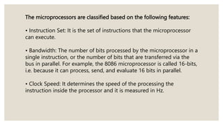
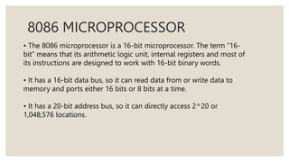
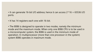
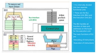
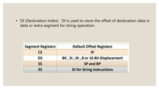
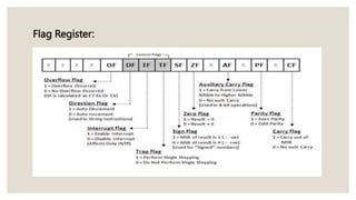
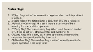
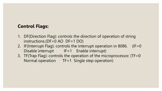
COMPUTER ORGANIZATION
AND ARCHITECTURE
8086 ARCHITECTURE
MICROPROCESSORS
The microprocessor is a general purpose programmable logic
device.
It is the brain of the computer and it performs all the
• computational tasks,
• calculations and
• data processing etc.
The latest intel microprocessor available is
Intel Core i9
The microprocessors are classified based on the following features:
• Instruction Set: It is the set of instructions that the microprocessor
can execute.
• Bandwidth: The number of bits processed by the microprocessor in a
single instruction, or the number of bits that are transferred via the
bus in parallel. For example, the 8086 microprocessor is called 16-bits,
i.e. because it can process, send, and evaluate 16 bits in parallel.
• Clock Speed: It determines the speed of the processing the
instruction inside the processor and it is measured in Hz.
8086 MICROPROCESSOR
• The 8086 microprocessor is a 16-bit microprocessor. The term “16-
bit” means that its arithmetic logic unit, internal registers and most of
its instructions are designed to work with 16-bit binary words.
• It has a 16-bit data bus, so it can read data from or write data to
memory and ports either 16 bits or 8 bits at a time.
• It has a 20-bit address bus, so it can directly access 2^20 or
1,048,576 locations.
• It can generate 16-bit I/O address; hence it can access 2^16 = 65536 I/O
ports.
• It has 14 registers each one with 16-bit.
• The 8086 is designed to operate in two modes, namely the minimum
mode and the maximum mode. When only one 8086 CPU is to be used in
a microcomputer system, the 8086 is used in the minimum mode of
operation. In multiprocessor (more than one processor in the system)
system 8086 operates in maximum mode.
• It is internally divided
into two separate
functional units.
• These are the Bus
Interface Unit (BIU) and
the Execution Unit (EU).
The BIU handles all
transfers of data and
addresses on the buses
for the execution unit.
The main functions of EU
are:
•Decoding of Instructions
•Execution of instructions
8086 has a powerful set of 16-bit registers known as: General &
Special Purpose registers.
•General Data Registers
•Segment Registers
•Pointers and Index Registers
•Flag Register
General Purpose Registers:
• Normally used for storing temporary results
• Each of the registers is 16 bits wide (AX, BX, CX, DX)
• Can be accessed as either 16 or 8 bits AX, AH, AL
•AX is used as 16-bit accumulator. The lower 8-bit is designated as AL
and higher 8-bit is designated as AH.
•BX is a 16 bit base register, to hold the starting base location of a
memory region. BL indicates the lower 8-bit of BX and BH indicates the
higher 8-bit of BX.
•The register CX is used as default counter i.e to hold count string, shift
and loop instructions.
•DX register is a general purpose register to contain I/O instructions.
Segment Registers:
• CS (Code Segment): It is the addressing memory location in the
memory, where the executable program is stored.
• SS (Stack Segment): It is used for addressing the memory. The stack
segment is that segment of memory which is used to store stack
data.
• DS (Data Segment): Points to the data segment of the memory
where the data is stored.
• ES(Extra Segment): Points to the additional data segment of the
memory where the data is stored.
Pointers and Index Registers:
• IP (Instruction pointer) contains off set within the code segment.
• BP (Base Pointer) Stores the base memory address and acts as an offset
to stack segment.
• SP (Stack Pointer) is Used to point the current top value of the stack and
act as an offset to the stack segment.
• SI (Source Index) is used to store the offset of source data in a data
segment for string operation .
• DI (Destination Index) DI is used to store the offset of destination data in
data or extra segment for string operation.
Flag Register:
Status Flags:
1. SF(Sign Flag): set to 1 when result is negative. when result is positive it
is set to 0.
2. ZF(Zero Flag): If the total register is zero, then only the Z flag is set
3. AF(Auxiliary Carry Flag): AF is set if there is a carry out of bit 3
resulting from an addition operation.
4. PF(Parity Flag): This is even parity flag. When result has even number
of 1, it will be set to 1, otherwise 0 for odd number of 1s
5. CF(Carry Flag): This is carry bit. If some operations are generating
carry after the operation this flag is set to 1
6. OF(Overflow Flag): The overflow flag is set to 1 when the result of a
signed operation is too large to fit.
Control Flags:
1. DF(Direction Flag): controls the direction of operation of string
instructions.(DF=0 AO DF=1 DO)
2. IF(Interrupt Flag): controls the interrupt operation in 8086. (IF=0
Disable interrupt IF=1 Enable interrupt)
3. TF(Trap Flag): controls the operation of the microprocessor. (TF=0
Normal operation TF=1 Single step operation)
THANKYOU
-A.SRI CHAITANYA
21BCE9543

Microprocessors

  • 1.
  • 2.
    MICROPROCESSORS The microprocessor isa general purpose programmable logic device. It is the brain of the computer and it performs all the • computational tasks, • calculations and • data processing etc. The latest intel microprocessor available is Intel Core i9
  • 3.
    The microprocessors areclassified based on the following features: • Instruction Set: It is the set of instructions that the microprocessor can execute. • Bandwidth: The number of bits processed by the microprocessor in a single instruction, or the number of bits that are transferred via the bus in parallel. For example, the 8086 microprocessor is called 16-bits, i.e. because it can process, send, and evaluate 16 bits in parallel. • Clock Speed: It determines the speed of the processing the instruction inside the processor and it is measured in Hz.
  • 4.
    8086 MICROPROCESSOR • The8086 microprocessor is a 16-bit microprocessor. The term “16- bit” means that its arithmetic logic unit, internal registers and most of its instructions are designed to work with 16-bit binary words. • It has a 16-bit data bus, so it can read data from or write data to memory and ports either 16 bits or 8 bits at a time. • It has a 20-bit address bus, so it can directly access 2^20 or 1,048,576 locations.
  • 5.
    • It cangenerate 16-bit I/O address; hence it can access 2^16 = 65536 I/O ports. • It has 14 registers each one with 16-bit. • The 8086 is designed to operate in two modes, namely the minimum mode and the maximum mode. When only one 8086 CPU is to be used in a microcomputer system, the 8086 is used in the minimum mode of operation. In multiprocessor (more than one processor in the system) system 8086 operates in maximum mode.
  • 6.
    • It isinternally divided into two separate functional units. • These are the Bus Interface Unit (BIU) and the Execution Unit (EU). The BIU handles all transfers of data and addresses on the buses for the execution unit. The main functions of EU are: •Decoding of Instructions •Execution of instructions
  • 7.
    8086 has apowerful set of 16-bit registers known as: General & Special Purpose registers. •General Data Registers •Segment Registers •Pointers and Index Registers •Flag Register
  • 8.
    General Purpose Registers: •Normally used for storing temporary results • Each of the registers is 16 bits wide (AX, BX, CX, DX) • Can be accessed as either 16 or 8 bits AX, AH, AL
  • 9.
    •AX is usedas 16-bit accumulator. The lower 8-bit is designated as AL and higher 8-bit is designated as AH. •BX is a 16 bit base register, to hold the starting base location of a memory region. BL indicates the lower 8-bit of BX and BH indicates the higher 8-bit of BX. •The register CX is used as default counter i.e to hold count string, shift and loop instructions. •DX register is a general purpose register to contain I/O instructions.
  • 10.
    Segment Registers: • CS(Code Segment): It is the addressing memory location in the memory, where the executable program is stored. • SS (Stack Segment): It is used for addressing the memory. The stack segment is that segment of memory which is used to store stack data. • DS (Data Segment): Points to the data segment of the memory where the data is stored. • ES(Extra Segment): Points to the additional data segment of the memory where the data is stored.
  • 11.
    Pointers and IndexRegisters: • IP (Instruction pointer) contains off set within the code segment. • BP (Base Pointer) Stores the base memory address and acts as an offset to stack segment. • SP (Stack Pointer) is Used to point the current top value of the stack and act as an offset to the stack segment. • SI (Source Index) is used to store the offset of source data in a data segment for string operation .
  • 12.
    • DI (DestinationIndex) DI is used to store the offset of destination data in data or extra segment for string operation.
  • 13.
  • 14.
    Status Flags: 1. SF(SignFlag): set to 1 when result is negative. when result is positive it is set to 0. 2. ZF(Zero Flag): If the total register is zero, then only the Z flag is set 3. AF(Auxiliary Carry Flag): AF is set if there is a carry out of bit 3 resulting from an addition operation. 4. PF(Parity Flag): This is even parity flag. When result has even number of 1, it will be set to 1, otherwise 0 for odd number of 1s 5. CF(Carry Flag): This is carry bit. If some operations are generating carry after the operation this flag is set to 1 6. OF(Overflow Flag): The overflow flag is set to 1 when the result of a signed operation is too large to fit.
  • 15.
    Control Flags: 1. DF(DirectionFlag): controls the direction of operation of string instructions.(DF=0 AO DF=1 DO) 2. IF(Interrupt Flag): controls the interrupt operation in 8086. (IF=0 Disable interrupt IF=1 Enable interrupt) 3. TF(Trap Flag): controls the operation of the microprocessor. (TF=0 Normal operation TF=1 Single step operation)
  • 16.