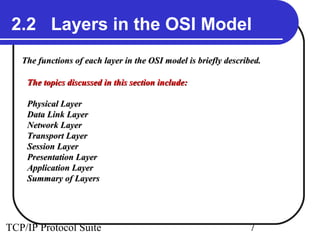
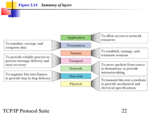
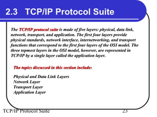
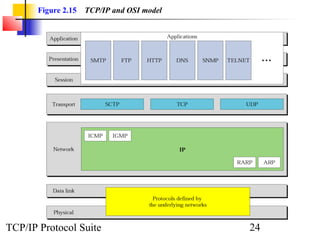
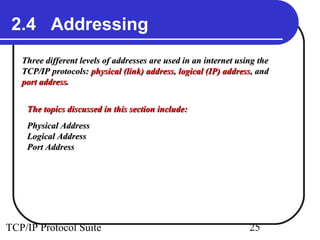
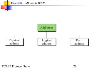
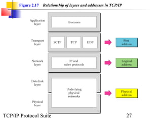
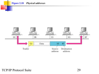
Chapter         2

           The OSI Model and
        the TCP/IP Protocol Suite
 Objectives
 Upon completion you will be able to:

 • Understand the architecture of the OSI model
 • Understand the layers of the OSI model and their functions
 • Understand the architecture of the TCP/IP Protocol Suite
 • Differentiate between the OSI model and the TCP/IP Suite
 • Differentiate between the three types of Internet addresses

TCP/IP Protocol Suite                                  1
2.1 The OSI Model
   Established in 1947, the International Standards Organization (ISO) is a
   multinational body dedicated to worldwide agreement on international
   standards. An ISO standard that covers all aspects of network
   communications is the Open Systems Interconnection (OSI) model. It
   was first introduced in the late 1970s.


    The topics discussed in this section include:

    Layered Architecture
    Peer-to-Peer Processes
    Encapsulation


TCP/IP Protocol Suite                                           2
Note:

                ISO is the organization.
                   OSI is the model


TCP/IP Protocol Suite                      3
Figure 2.1   The OSI model


TCP/IP Protocol Suite               4
Figure 2.2   OSI layers


TCP/IP Protocol Suite            5
Figure 2.3   An exchange using the OSI model


TCP/IP Protocol Suite                                 6
2.2 Layers in the OSI Model
   The functions of each layer in the OSI model is briefly described.

    The topics discussed in this section include:

    Physical Layer
    Data Link Layer
    Network Layer
    Transport Layer
    Session Layer
    Presentation Layer
    Application Layer
    Summary of Layers


TCP/IP Protocol Suite                                            7
Figure 2.4   Physical layer


TCP/IP Protocol Suite                8
Note:

         The physical layer is responsible
        for the movement of individual bits
         from one hop (node) to the next.


TCP/IP Protocol Suite                 9
Figure 2.5   Data link layer


TCP/IP Protocol Suite                 10
Note:

       The data link layer is responsible for
      moving frames from one hop (node) to
                     the next.


TCP/IP Protocol Suite                  11
Figure 2.6   Hop-to-hop delivery


TCP/IP Protocol Suite                     12
Figure 2.7   Network layer


TCP/IP Protocol Suite               13
Note:

       The network layer is responsible for
     the delivery of individual packets from
     the source host to the destination host.


TCP/IP Protocol Suite                  14
Figure 2.8   Source-to-destination delivery


TCP/IP Protocol Suite                                15
Figure 2.9   Transport layer


TCP/IP Protocol Suite                 16
Note:

       The transport layer is responsible for
        the delivery of a message from one
                process to another.


TCP/IP Protocol Suite                  17
Figure 2.10   Reliable process-to-process delivery of a message


TCP/IP Protocol Suite                                                    18
Figure 2.11   Session layer


TCP/IP Protocol Suite                19
Figure 2.12   Presentation layer


TCP/IP Protocol Suite                     20
Figure 2.13   Application layer


TCP/IP Protocol Suite                    21
Figure 2.14   Summary of layers


TCP/IP Protocol Suite                    22
2.3 TCP/IP Protocol Suite
   The TCP/IP protocol suite is made of five layers: physical, data link,
   network, transport, and application. The first four layers provide
   physical standards, network interface, internetworking, and transport
   functions that correspond to the first four layers of the OSI model. The
   three topmost layers in the OSI model, however, are represented in
   TCP/IP by a single layer called the application layer.

    The topics discussed in this section include:

    Physical and Data Link Layers
    Network Layer
    Transport Layer
    Application Layer


TCP/IP Protocol Suite                                            23
Figure 2.15   TCP/IP and OSI model


TCP/IP Protocol Suite                       24
2.4 Addressing
   Three different levels of addresses are used in an internet using the
   TCP/IP protocols: physical (link) address, logical (IP) address, and
   port address.


    The topics discussed in this section include:
    Physical Address
    Logical Address
    Port Address


TCP/IP Protocol Suite                                             25
Figure 2.16   Addresses in TCP/IP


TCP/IP Protocol Suite                      26
Figure 2.17   Relationship of layers and addresses in TCP/IP


TCP/IP Protocol Suite                                                 27
ExamplE 1


 In Figure 2.18 a node with physical address 10 sends
 a frame to a node with physical address 87. The two
 nodes are connected by a link. At the data link level
 this frame contains physical (link) addresses in the
 header. These are the only addresses needed. The rest
 of the header contains other information needed at
 this level. The trailer usually contains extra bits
 needed for error detection.

                        See Next Slide

TCP/IP Protocol Suite                        28
Figure 2.18   Physical addresses


TCP/IP Protocol Suite                     29
ExamplE 2


 As we will see in Chapter 3, most local area networks
 use a 48-bit (6 bytes) physical address written as 12
 hexadecimal digits, with every 2 bytes separated by a
 colon as shown below:

                        07:01:02:01:2C:4B
     A 6-byte (12 hexadecimal digits) physical address.


TCP/IP Protocol Suite                          30
ExamplE 3


 In Figure 2.19 we want to send data from a node with network
 address A and physical address 10, located on one LAN, to a
 node with a network address P and physical address 95, located
 on another LAN. Because the two devices are located on
 different networks, we cannot use link addresses only; the link
 addresses have only local jurisdiction. What we need here are
 universal addresses that can pass through the LAN
 boundaries. The network (logical) addresses have this
 characteristic.


                        See Next Slide

TCP/IP Protocol Suite                                 31
ExamplE 3
        (Continued)


 The packet at the network layer contains the logical addresses,
 which remain the same from the original source to the final
 destination (A and P, respectively, in the figure). They will not
 change when we go from network to network. However, the
 physical addresses will change as the packet moves from one
 network to another. The boxes labeled routers are
 internetworking devices, which we will discuss in Chapter 3.


                        See Next Slide

TCP/IP Protocol Suite                                  32
Figure 2.19   IP addresses


TCP/IP Protocol Suite               33
ExamplE 4


 As we will see in Chapter 4, an Internet address (in
 IPv4) is 32 bits in length, normally written as four
 decimal numbers, with each number representing 1
 byte. The numbers are separated by a dot. Below is an
 example of such an address.

                       132.24.75.9
     An internet address in IPv4 in decimal numbers


TCP/IP Protocol Suite                         34
ExamplE 5


 Figure 2.20 shows an example of transport layer
 communication. Data coming from the upperlayers
 have port addresses j and k ( j is the address of the
 sending process, and k is the address of the receiving
 process). Since the data size is larger than the network
 layer can handle, the data are split into two packets,
 each packet retaining the service-point addresses ( j
 and k). Then in the network layer, network addresses
 (A and P) are added to each packet.

                        See Next Slide
TCP/IP Protocol Suite                           35
ExamplE 5       (Continued)


 The packets can travel on different paths and arrive at
 the destination either in order or out of order. The two
 packets are delivered to the destination transport
 layer, which is responsible for removing the network
 layer headers and combining the two pieces of data
 for delivery to the upper layers.


                        See Next Slide


TCP/IP Protocol Suite                           36
Figure 2.20   Port addresses


TCP/IP Protocol Suite                 37
ExamplE 6


 As we will see in Chapters 11, 12, and 13, a port
 address is a 16-bit address represented by one decimal
 number as shown below.

                           753
 A 16-bit port address represented as one single number.


TCP/IP Protocol Suite                         38
2.5 IP Versions
   IP became the official protocol for the Internet in 1983. As the Internet
   has evolved, so has IP. There have been six versions since its inception.
   We look at the latter three versions here.


    The topics discussed in this section include:
    Version 4
    Version 5
    Version 6


TCP/IP Protocol Suite                                             39

Chap 02

  • 1.
    Chapter 2 The OSI Model and the TCP/IP Protocol Suite Objectives Upon completion you will be able to: • Understand the architecture of the OSI model • Understand the layers of the OSI model and their functions • Understand the architecture of the TCP/IP Protocol Suite • Differentiate between the OSI model and the TCP/IP Suite • Differentiate between the three types of Internet addresses TCP/IP Protocol Suite 1
  • 2.
    2.1 The OSIModel Established in 1947, the International Standards Organization (ISO) is a multinational body dedicated to worldwide agreement on international standards. An ISO standard that covers all aspects of network communications is the Open Systems Interconnection (OSI) model. It was first introduced in the late 1970s. The topics discussed in this section include: Layered Architecture Peer-to-Peer Processes Encapsulation TCP/IP Protocol Suite 2
  • 3.
    Note: ISO is the organization. OSI is the model TCP/IP Protocol Suite 3
  • 4.
    Figure 2.1 The OSI model TCP/IP Protocol Suite 4
  • 5.
    Figure 2.2 OSI layers TCP/IP Protocol Suite 5
  • 6.
    Figure 2.3 An exchange using the OSI model TCP/IP Protocol Suite 6
  • 7.
    2.2 Layers inthe OSI Model The functions of each layer in the OSI model is briefly described. The topics discussed in this section include: Physical Layer Data Link Layer Network Layer Transport Layer Session Layer Presentation Layer Application Layer Summary of Layers TCP/IP Protocol Suite 7
  • 8.
    Figure 2.4 Physical layer TCP/IP Protocol Suite 8
  • 9.
    Note: The physical layer is responsible for the movement of individual bits from one hop (node) to the next. TCP/IP Protocol Suite 9
  • 10.
    Figure 2.5 Data link layer TCP/IP Protocol Suite 10
  • 11.
    Note: The data link layer is responsible for moving frames from one hop (node) to the next. TCP/IP Protocol Suite 11
  • 12.
    Figure 2.6 Hop-to-hop delivery TCP/IP Protocol Suite 12
  • 13.
    Figure 2.7 Network layer TCP/IP Protocol Suite 13
  • 14.
    Note: The network layer is responsible for the delivery of individual packets from the source host to the destination host. TCP/IP Protocol Suite 14
  • 15.
    Figure 2.8 Source-to-destination delivery TCP/IP Protocol Suite 15
  • 16.
    Figure 2.9 Transport layer TCP/IP Protocol Suite 16
  • 17.
    Note: The transport layer is responsible for the delivery of a message from one process to another. TCP/IP Protocol Suite 17
  • 18.
    Figure 2.10 Reliable process-to-process delivery of a message TCP/IP Protocol Suite 18
  • 19.
    Figure 2.11 Session layer TCP/IP Protocol Suite 19
  • 20.
    Figure 2.12 Presentation layer TCP/IP Protocol Suite 20
  • 21.
    Figure 2.13 Application layer TCP/IP Protocol Suite 21
  • 22.
    Figure 2.14 Summary of layers TCP/IP Protocol Suite 22
  • 23.
    2.3 TCP/IP ProtocolSuite The TCP/IP protocol suite is made of five layers: physical, data link, network, transport, and application. The first four layers provide physical standards, network interface, internetworking, and transport functions that correspond to the first four layers of the OSI model. The three topmost layers in the OSI model, however, are represented in TCP/IP by a single layer called the application layer. The topics discussed in this section include: Physical and Data Link Layers Network Layer Transport Layer Application Layer TCP/IP Protocol Suite 23
  • 24.
    Figure 2.15 TCP/IP and OSI model TCP/IP Protocol Suite 24
  • 25.
    2.4 Addressing Three different levels of addresses are used in an internet using the TCP/IP protocols: physical (link) address, logical (IP) address, and port address. The topics discussed in this section include: Physical Address Logical Address Port Address TCP/IP Protocol Suite 25
  • 26.
    Figure 2.16 Addresses in TCP/IP TCP/IP Protocol Suite 26
  • 27.
    Figure 2.17 Relationship of layers and addresses in TCP/IP TCP/IP Protocol Suite 27
  • 28.
    ExamplE 1 InFigure 2.18 a node with physical address 10 sends a frame to a node with physical address 87. The two nodes are connected by a link. At the data link level this frame contains physical (link) addresses in the header. These are the only addresses needed. The rest of the header contains other information needed at this level. The trailer usually contains extra bits needed for error detection. See Next Slide TCP/IP Protocol Suite 28
  • 29.
    Figure 2.18 Physical addresses TCP/IP Protocol Suite 29
  • 30.
    ExamplE 2 Aswe will see in Chapter 3, most local area networks use a 48-bit (6 bytes) physical address written as 12 hexadecimal digits, with every 2 bytes separated by a colon as shown below: 07:01:02:01:2C:4B A 6-byte (12 hexadecimal digits) physical address. TCP/IP Protocol Suite 30
  • 31.
    ExamplE 3 InFigure 2.19 we want to send data from a node with network address A and physical address 10, located on one LAN, to a node with a network address P and physical address 95, located on another LAN. Because the two devices are located on different networks, we cannot use link addresses only; the link addresses have only local jurisdiction. What we need here are universal addresses that can pass through the LAN boundaries. The network (logical) addresses have this characteristic. See Next Slide TCP/IP Protocol Suite 31
  • 32.
    ExamplE 3 (Continued) The packet at the network layer contains the logical addresses, which remain the same from the original source to the final destination (A and P, respectively, in the figure). They will not change when we go from network to network. However, the physical addresses will change as the packet moves from one network to another. The boxes labeled routers are internetworking devices, which we will discuss in Chapter 3. See Next Slide TCP/IP Protocol Suite 32
  • 33.
    Figure 2.19 IP addresses TCP/IP Protocol Suite 33
  • 34.
    ExamplE 4 Aswe will see in Chapter 4, an Internet address (in IPv4) is 32 bits in length, normally written as four decimal numbers, with each number representing 1 byte. The numbers are separated by a dot. Below is an example of such an address. 132.24.75.9 An internet address in IPv4 in decimal numbers TCP/IP Protocol Suite 34
  • 35.
    ExamplE 5 Figure2.20 shows an example of transport layer communication. Data coming from the upperlayers have port addresses j and k ( j is the address of the sending process, and k is the address of the receiving process). Since the data size is larger than the network layer can handle, the data are split into two packets, each packet retaining the service-point addresses ( j and k). Then in the network layer, network addresses (A and P) are added to each packet. See Next Slide TCP/IP Protocol Suite 35
  • 36.
    ExamplE 5 (Continued) The packets can travel on different paths and arrive at the destination either in order or out of order. The two packets are delivered to the destination transport layer, which is responsible for removing the network layer headers and combining the two pieces of data for delivery to the upper layers. See Next Slide TCP/IP Protocol Suite 36
  • 37.
    Figure 2.20 Port addresses TCP/IP Protocol Suite 37
  • 38.
    ExamplE 6 Aswe will see in Chapters 11, 12, and 13, a port address is a 16-bit address represented by one decimal number as shown below. 753 A 16-bit port address represented as one single number. TCP/IP Protocol Suite 38
  • 39.
    2.5 IP Versions IP became the official protocol for the Internet in 1983. As the Internet has evolved, so has IP. There have been six versions since its inception. We look at the latter three versions here. The topics discussed in this section include: Version 4 Version 5 Version 6 TCP/IP Protocol Suite 39