The document discusses various parameters of antennas:
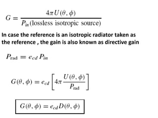
- Gain is the ratio of radiation intensity compared to an isotropic radiator and takes into account efficiency. Relative gain compares antennas using the same input power.
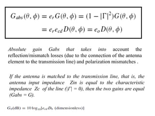
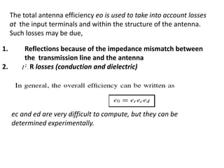
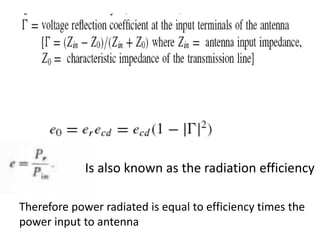
- Efficiency accounts for losses within the antenna from reflections, resistance, and dielectrics. It is the ratio of radiated power to total input power.
- Bandwidth is the range of frequencies over which the antenna characteristics meet specifications around the center frequency. It can be expressed as a ratio or percentage.
- Polarization describes the time-varying direction and magnitude of the electric field and can be linear, elliptical, or circular.