
Recommended
More Related Content
What's hot
More from PhysicsJackson
Recently uploaded
Recently uploaded (20)
Ch2sum
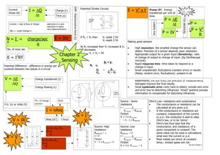
- 1. EMF: Electromotive force (E) Potential Divider Circuits Current I = ∆Q Charge (c) E = V2 x t Power (P) - Energy J/s - watt Amps (A) transferred per unit of ∆t Time (s) time. R1 V1 P = ∆E For electricity 5V DC P= Vin Any System Current = rate of flow of charge -electrons in a wire -electrons in beam R2 V2 ∆t P = V2 or... -ions (beam/solution) NB:∆ = small change in P = IV R If R1 = R2 then V1 reads 2.5V N=I = charge/sec E = ItV V2 reads 2.5V Making good sensors q As R2 increases then V2 increases & V1 • High resolution -the smallest change the sensor can No. of ions/ sec decreases detect. Precision of a sensor depends upon resolution. V1 + V2 ≡ 5V 2 Chapter 2 • Appropriate output for a given input (Sensitivity) -ratio E = I RT of change of output to change of input. (Eg Oscilloscope Sensing R1 = V1 mm/volt) • Rapid response time –time taken to respond to a Potential Difference - difference in energy per R2 v2 change in input. coulomb between two places in a circuit V2 = R2__ • Small unsystematic fluctuations (random error) in results Vin R1 + R2 (Noise, random error, fluctuations) -present in all V = ∆E Energy transferred (J) experiments, the size limits the precision of measurements. ∆Q Averages improve the final results. Energy flowing (c) • Small systematic error –very hard to detect, include zero error and error due to disturbing influences. ‘Smart’ systems process Rinternal Rinternal Output information to compensate for disturbing influences. Rexternal EMF (E) No. of charge Drift Source : Some Ohm’s Law –resistance and conductance P.d. J/c or Volts (V) carriers resistance • The conductance or resistance can be I= E_______ calculated at any given p.d. I = nAvq Rexternal + Rinternal • If the conductance or resistance are Output constant, independent of the current G=I V = I x Rexternal or p.d., the conductor is said to obey V = IR 3 Area (m ) Charge V = E - I x Rinternal Ohm’s law, or to be ‘ohmic’. • Ohm's law thus says that the Source: High Source: Low conductance, and resistance, of a G=G1+G2+G3… A1 resistance resistance given component is constant. The R=1 R1 Rinternal ≈ ∞ Rinternal ≈ 0 same value can be used in calculations G R=V V R1 R2 R2 I≈0 Output I= E_______ Rexternal + Rinternal • what ever the current or p.d. Most metals are ohmic at constant R=R1+R2+R3… V I A1 A2 G=1 A1 R2 V = I x Rexternal ≈ 0 Output temp.; ionised gases are not. A1+A2 R A1 V = I x Rexternal ≈ E See also Chapter 4