Download as PDF, PPTX
![Terminology Unique to Two Phase
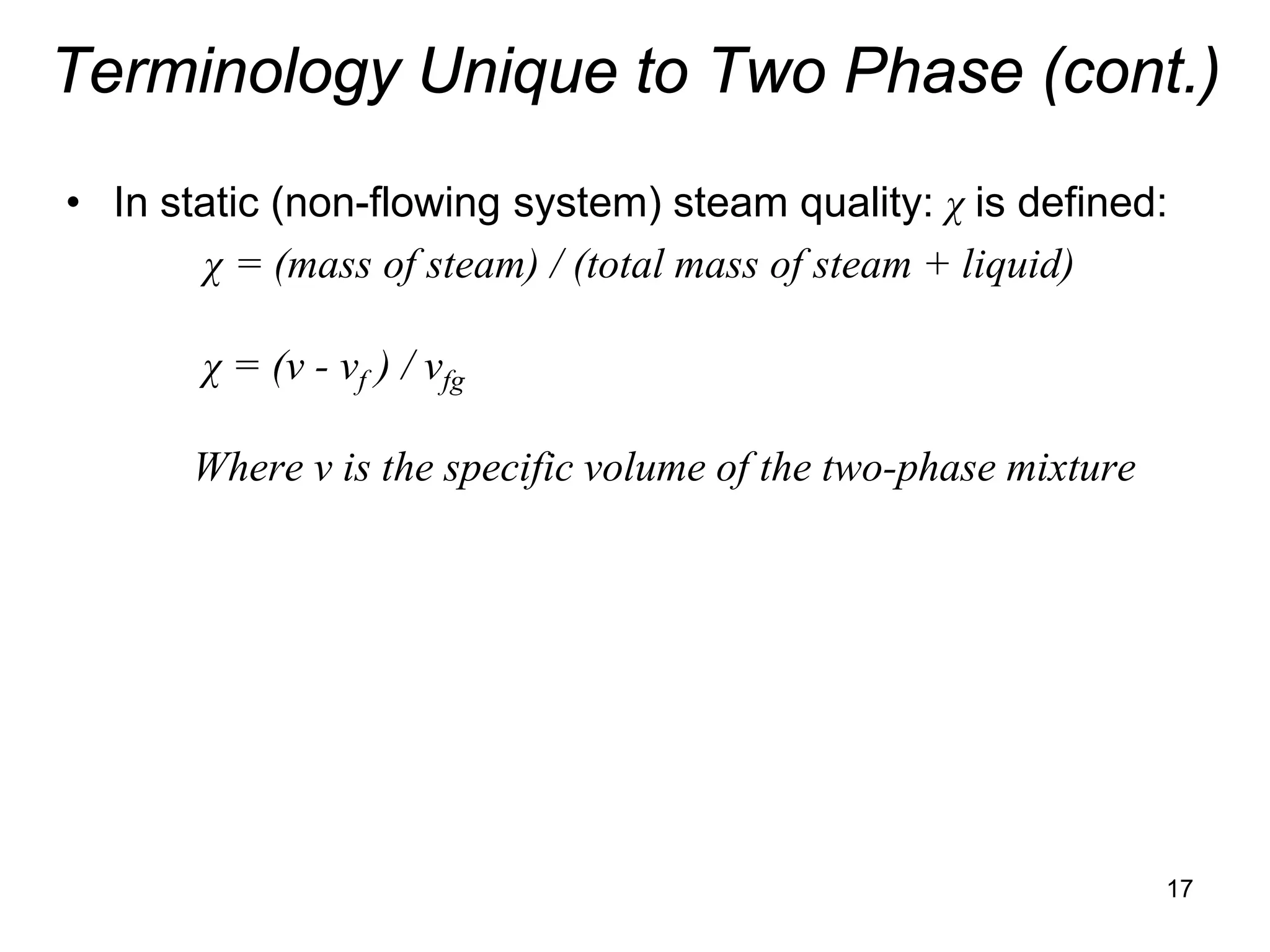
• In static (non-flowing system) steam quality: χ is defined:
χ = (mass of steam) / (total mass of steam + liquid)
• In static (non-flowing system) void fraction: α is defined:
α = (volume of steam in mixture) / (total volume of steam + liquid)
• Void fraction can be expressed in terms of steam quality
and specific volumes (from Steam Tables) as follows:
α = χvg / ((1- χ )vf + χvg ) = 1 / {1 + [(1 – χ)/ χ] vf / vg }
• Where: vg is specific volume of steam in ft3/lb-m
vf is specific volume of liquid in ft3/lb-m
vfg = vg - vf is difference in specific volumes
Good source for fluid properties: http://webbook.nist.gov/chemistry/fluid/
16](https://image.slidesharecdn.com/module12twophasefluidflowandheattransfer2010junenrc-12779909090564-phpapp02/75/Module-12-Two-Phase-Fluid-Flow-And-Heat-Transfer-2010-June-Nrc-16-2048.jpg)

24](https://image.slidesharecdn.com/module12twophasefluidflowandheattransfer2010junenrc-12779909090564-phpapp02/75/Module-12-Two-Phase-Fluid-Flow-And-Heat-Transfer-2010-June-Nrc-24-2048.jpg)
![Definition of Void Fraction in Terms of
Steam Quality and Slip
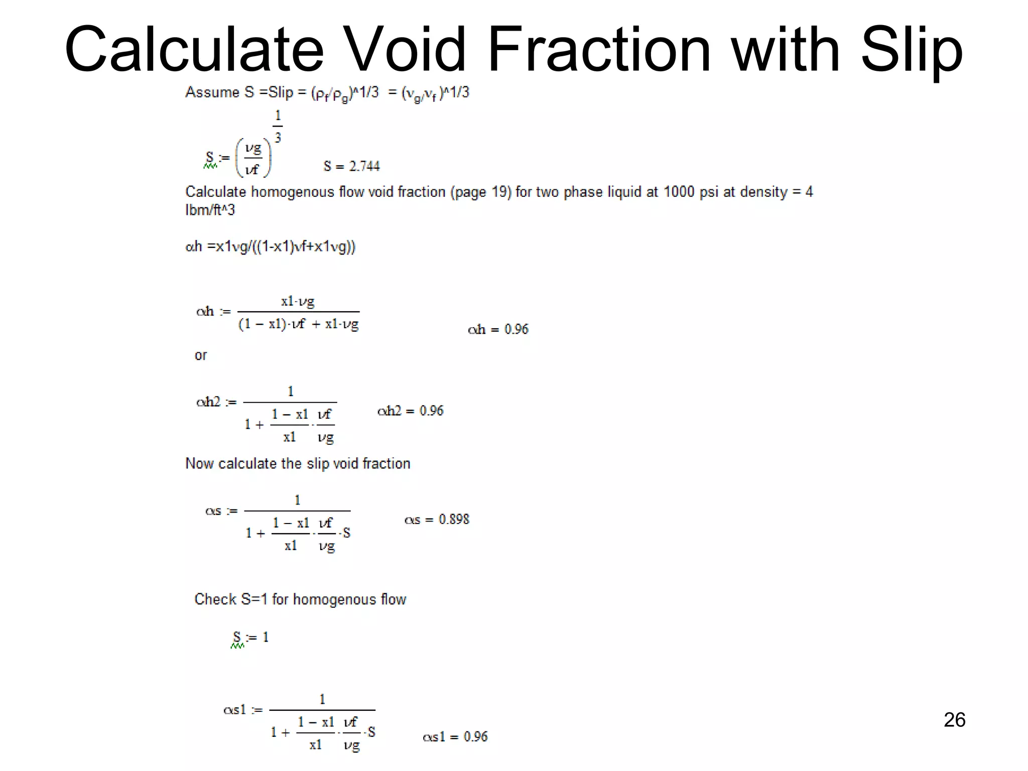
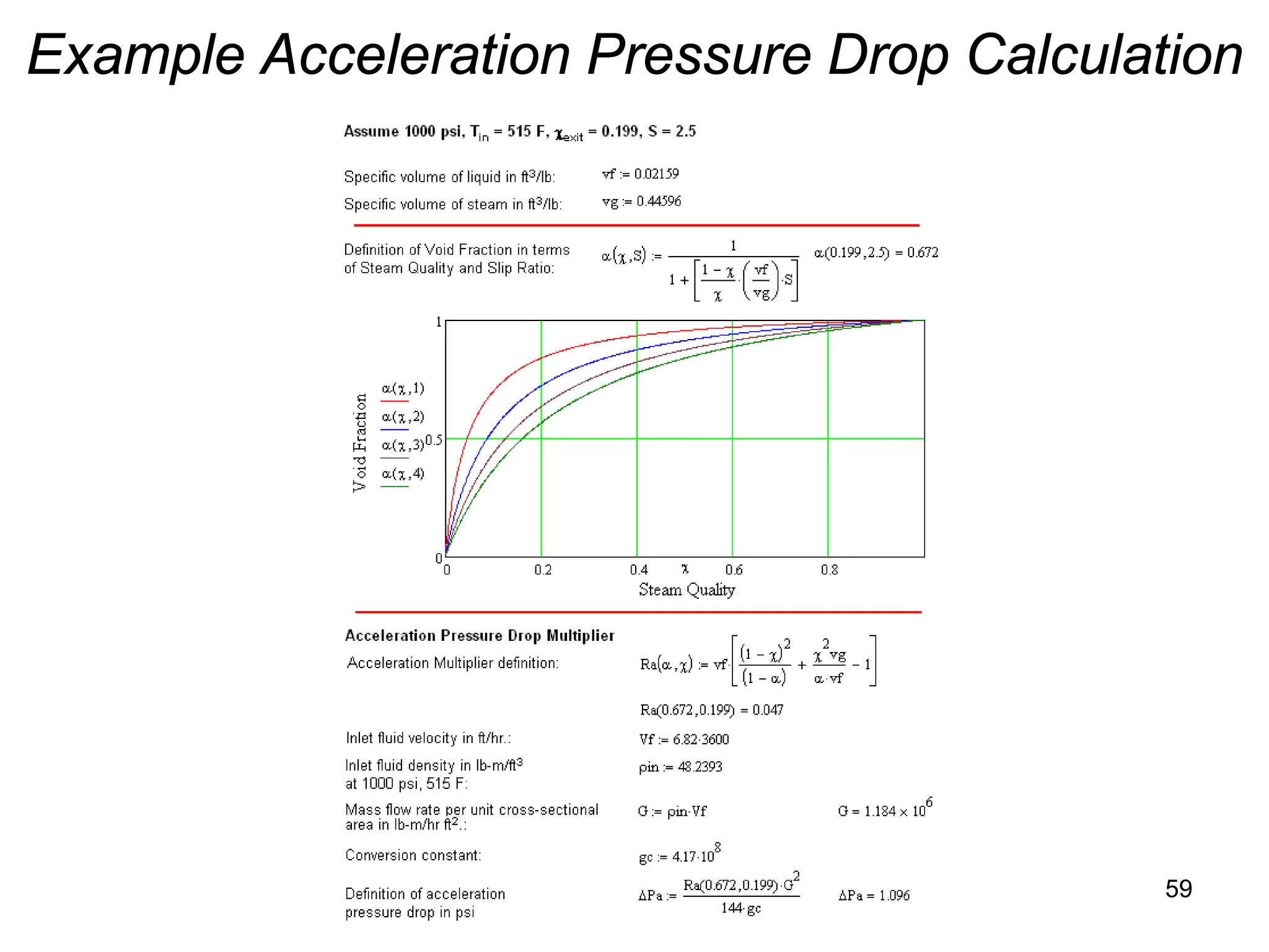
• Slip equation can be rearranged to define void fraction: α
in terms of steam quality and Slip:
1
α=
(1 − χ ) v f
1+ [ ] S
χ vg
• When S = 1: steam and liquid move at exact same speed
Effect of slip:
• Slip decreases void fraction α(χ) below that which exists in
situation of no slip between steam and liquid 25](https://image.slidesharecdn.com/module12twophasefluidflowandheattransfer2010junenrc-12779909090564-phpapp02/75/Module-12-Two-Phase-Fluid-Flow-And-Heat-Transfer-2010-June-Nrc-25-2048.jpg)


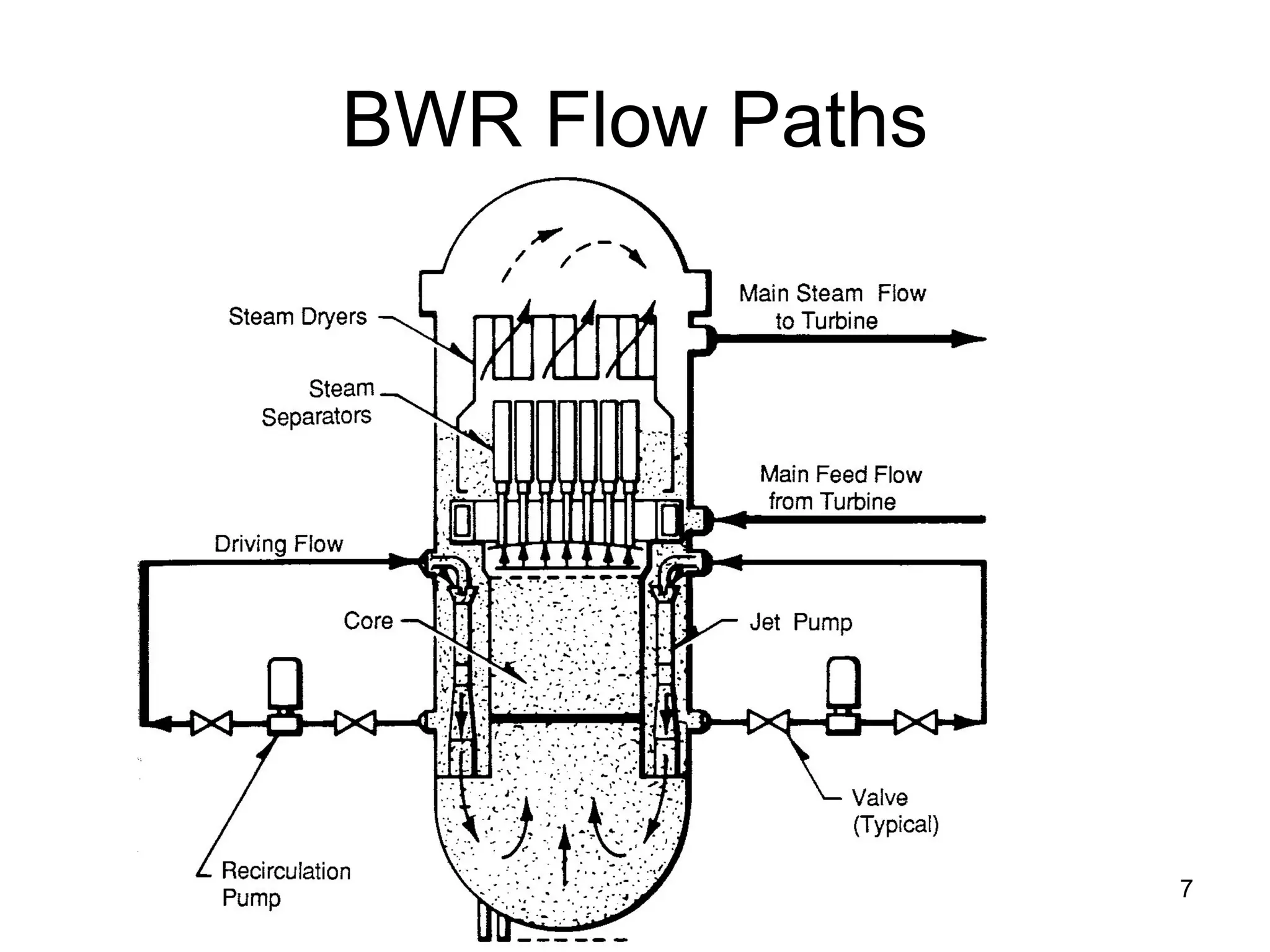
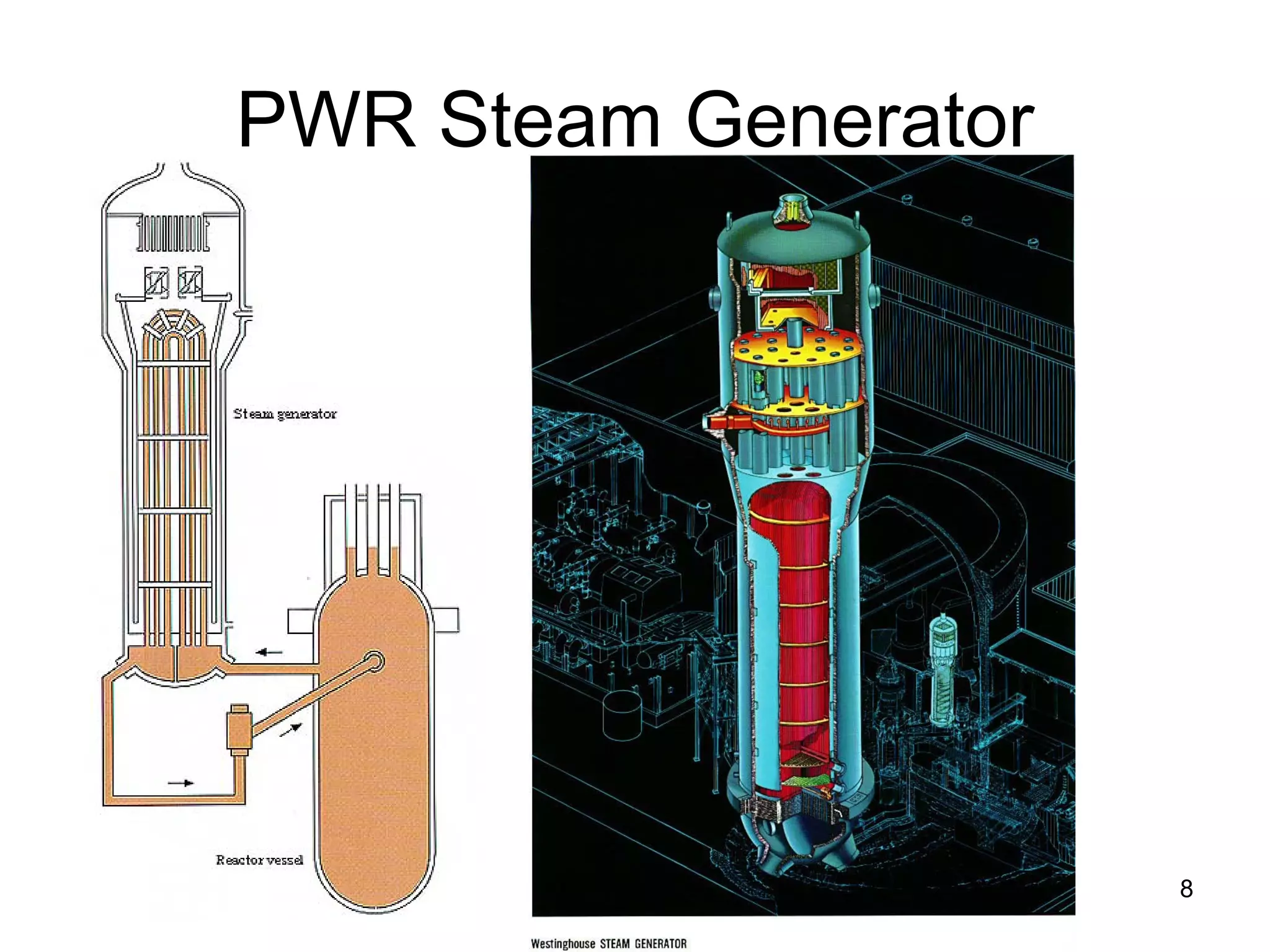
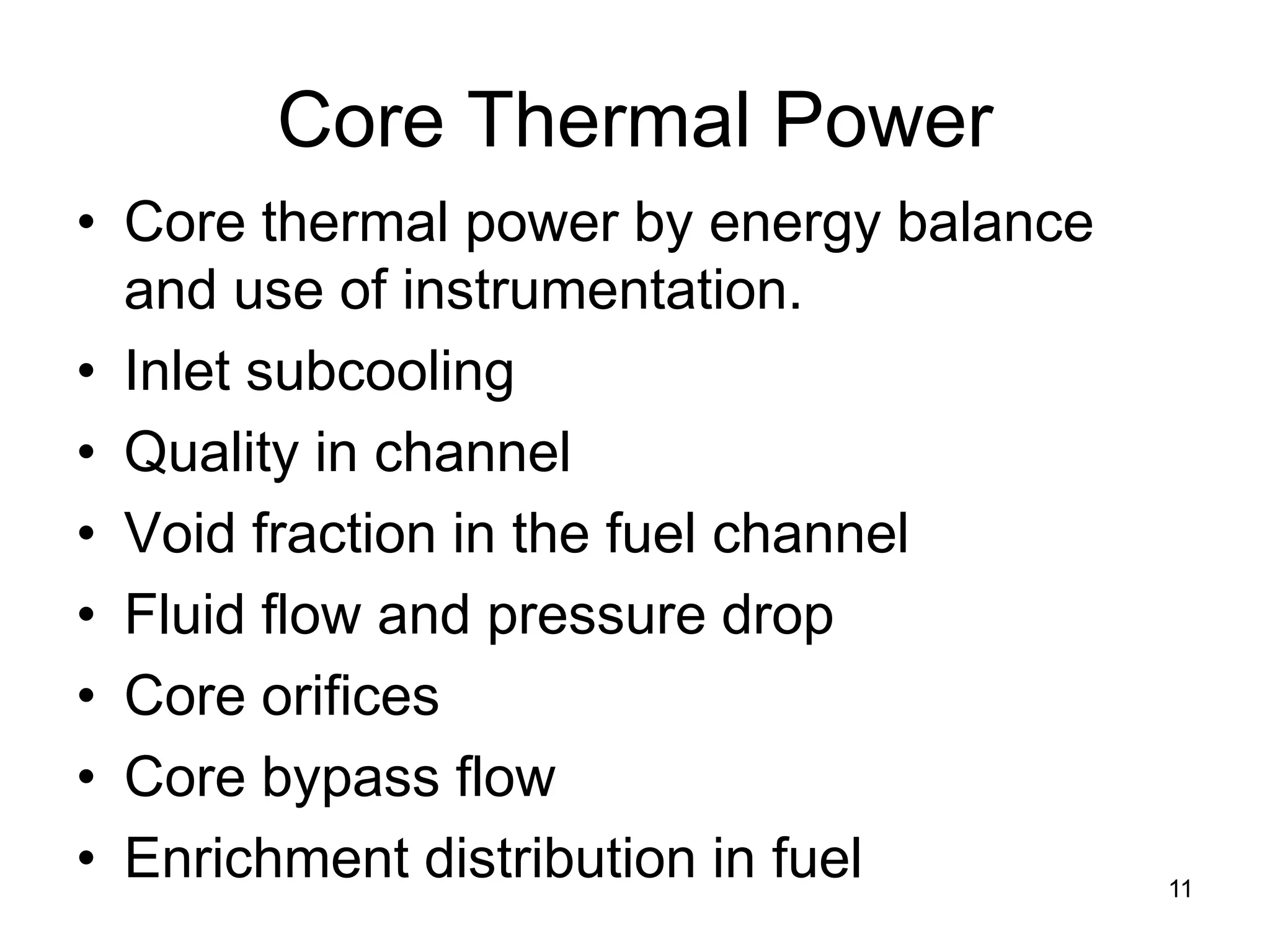
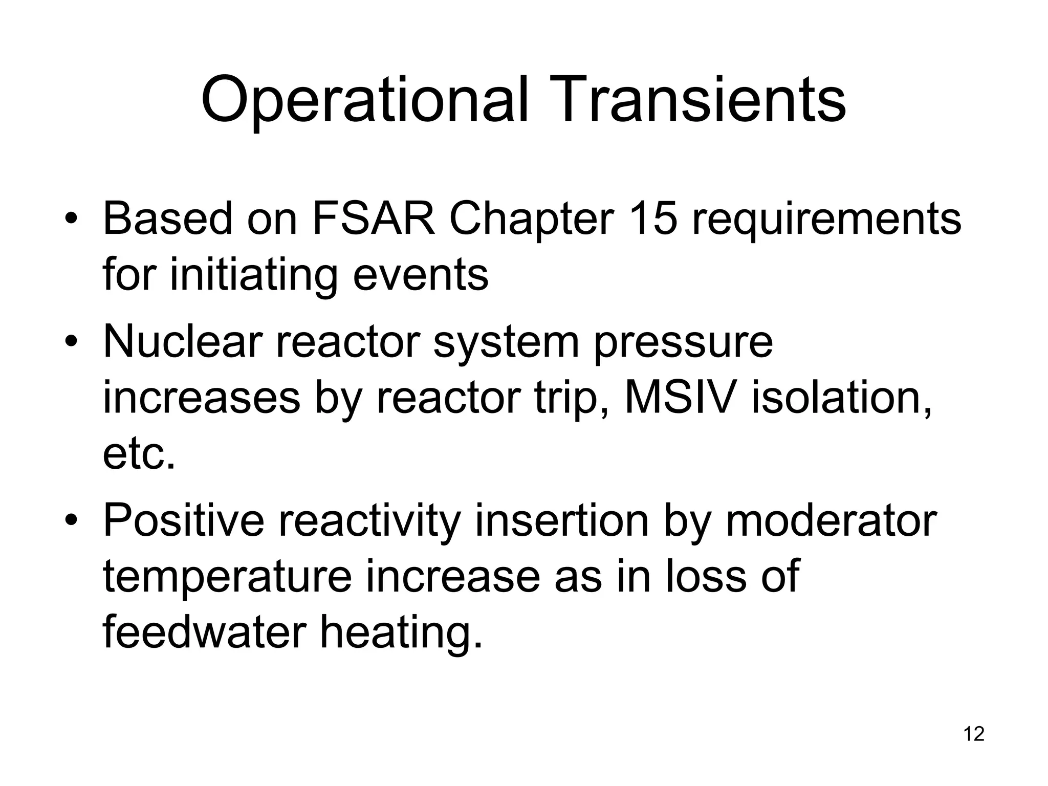
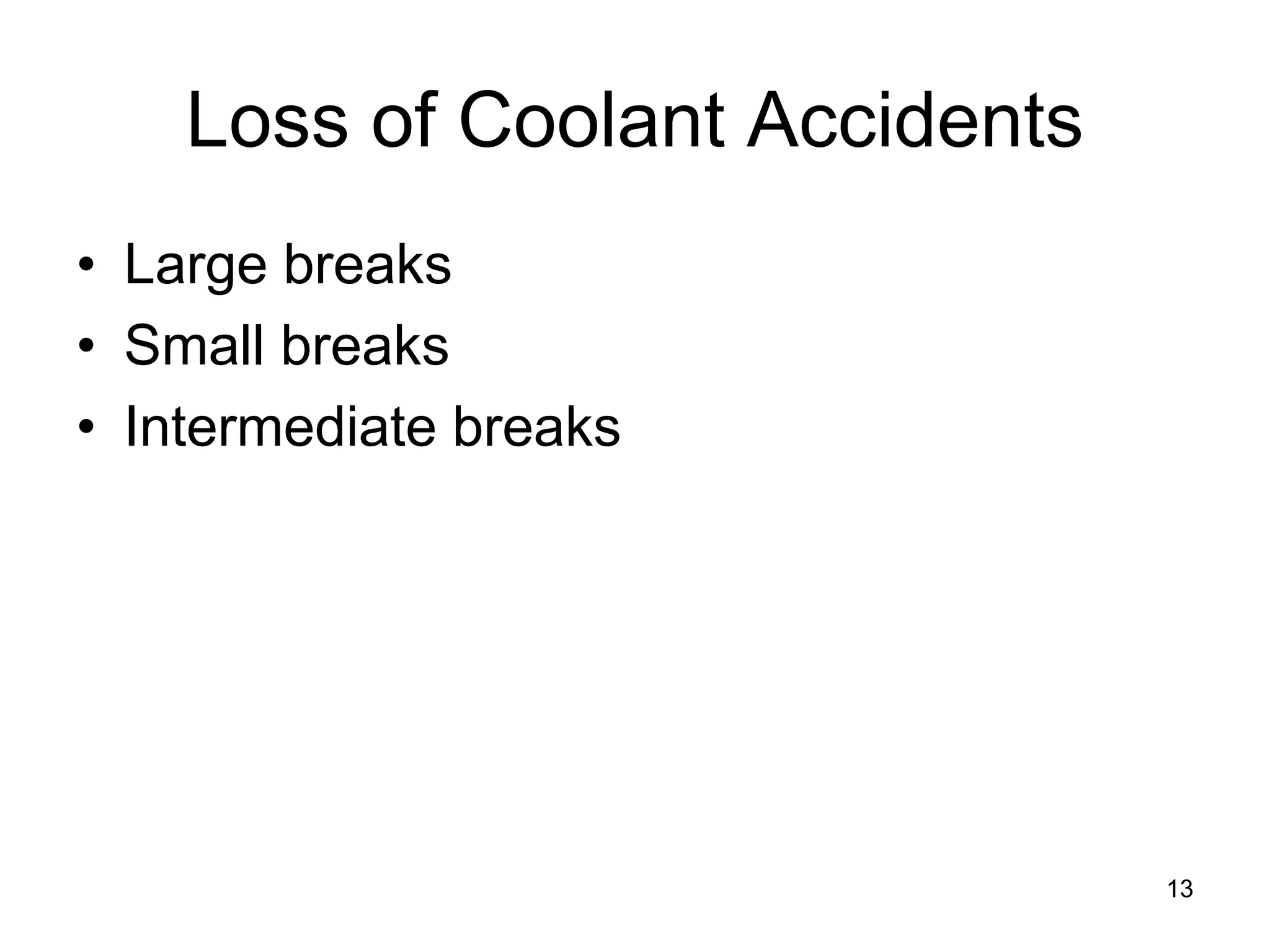
This document focuses on two-phase heat transfer and fluid flow in nuclear engineering, specifically in boiling water reactors (BWRs). It covers key concepts such as thermal-hydraulic stages, two-phase flow equations, and pressure drops while detailing heat transfer regimes and behaviors during operational transients and accidents. The lecture aims to enhance understanding of complex interactions between coolant and fuel in two-phase systems.


![Coded Agents – with UiPath SDK + LangGraph [Virtual Hands-on Workshop]](https://cdn.slidesharecdn.com/ss_thumbnails/codedagentsdeck-251215155422-5497c599-thumbnail.jpg?width=640&height=640&fit=bounds)


