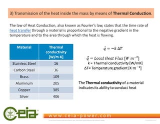
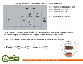
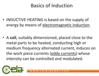
This document discusses the principles and applications of induction heating. It describes how induction heating works by using electromagnetic induction to generate eddy currents in conductive materials, causing them to heat up. The main applications listed are brazing, soldering, heat treatment, melting, and forging of metals. The document also covers the advantages of induction heating like localized and efficient heating. It provides details on the physics behind induction heating regarding electromagnetic fields, skin effect, and heat transfer through conduction. Historical generator designs starting from valve oscillators to modern solid state transistors are outlined.
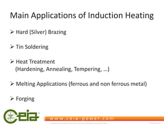
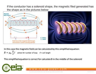
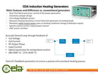
![The Laplace Law states that the intensity of the magnetic field is reverse proportional to the square of the
distance.
In case of a single loop coil, the intensity of the magnetic flow at the point P, whose distance from the coil center is z,
Is given by the simplified equation:
0
5
10
15
20
25
30
35
0 1 2 3 4 5 6 7 8 9 10 11 12 13 14 15 16 17 18 19 20
B
[mT]
z = Coil Gap [mm]
Magnetic Field intensity vs. Coil distance
Coil = Ɍ 15mm
This document is property of CEIA which reserves all rights. Total or partial copying, modification and translation is forbidden FC040K0068V1000UK](https://image.slidesharecdn.com/ceiainductionheatingprinciplesfc040k0068v1uk2-211031153307/85/Ceia-induction-heatingprinciples_fc040k0068v1uk-2-10-320.jpg)
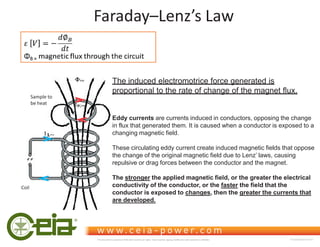
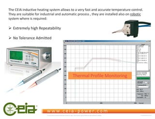
![The magnetic permeability of a material is the capability of this material to channel magnetic induction.
In fact, magnetic field H and magnetic induction field B are linked, in a given material, by the equation :
B = μ * H
where μ is the magnetic permeability of the material (in Henry/meter). μ=μ0 * μr
- μ0 is a universal constant, equal to ϰʋΎϭϬ-7 H/m
- μr depends on the material.
The materials can be classified in:
¾Diamagnetic (copper, gold, silver, aluminum oxide) μr чϭ
¾Paramagnetic (aluminum, titanium, molybdenum, stainless steel) μr шϭ
¾Ferromagnetic (carbon steel) μr 1
The magnetic permeability of ferromagnetic materials above the Curie temperature , ƐƵĚĚĞŶůLJĚƌŽƉĚŽǁŶƚŽʅr =1
Electro – Magnetic Features of Metals
Material Curie Temperature
[°C]
Cobalt 1115
Iron 770
Nickel 358
This document is property of CEIA which reserves all rights. Total or partial copying, modification and translation is forbidden FC040K0068V1000UK](https://image.slidesharecdn.com/ceiainductionheatingprinciplesfc040k0068v1uk2-211031153307/85/Ceia-induction-heatingprinciples_fc040k0068v1uk-2-12-320.jpg)
![Frequecy
[Hz]
Steel
AISI 316
(ʅr =1)
Copper
Cu
(ʅr ~1)
Steel
AISI 420
(ʅr =2000)
100 43,32 6,68 0,83
1.000 13,70 2,11 0,26
10.000 4,33 0,67 0,08
100.000 1,37 0,21 0,026
200.000 0,97 0,15 0,019
1.000.000 0,43 0,067 0,008
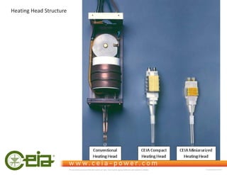
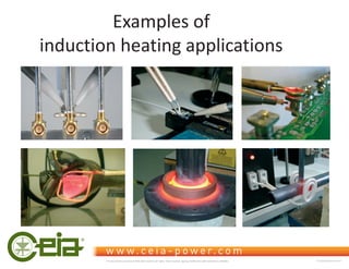
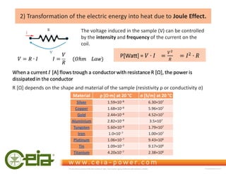
Skin Depth
ŵŵ
Skin Depth Calculation
Calculation of skin depth at different frequency for magnetic and not-magnetic material
This document is property of CEIA which reserves all rights. Total or partial copying, modification and translation is forbidden FC040K0068V1000UK](https://image.slidesharecdn.com/ceiainductionheatingprinciplesfc040k0068v1uk2-211031153307/85/Ceia-induction-heatingprinciples_fc040k0068v1uk-2-16-320.jpg)
![0,00
0,01
0,10
1,00
10,00
100,00
1.000,00
1 10 100 1.000 10.000 100.000 1.000.000
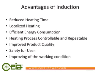
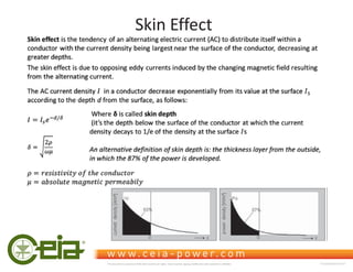
Skin
depth
[mm]
Frequency [Hz]
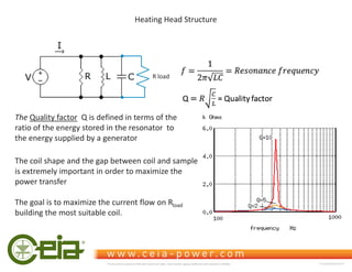
Skin depth versus frequency
Low conductivity diamagnetic metal (AISI316)
Good conductivity diamagnetic metal (Cu)
Ferromagnetic metal (AISI420 - ur 2000)
This document is property of CEIA which reserves all rights. Total or partial copying, modification and translation is forbidden FC040K0068V1000UK](https://image.slidesharecdn.com/ceiainductionheatingprinciplesfc040k0068v1uk2-211031153307/85/Ceia-induction-heatingprinciples_fc040k0068v1uk-2-17-320.jpg)