Download to read offline

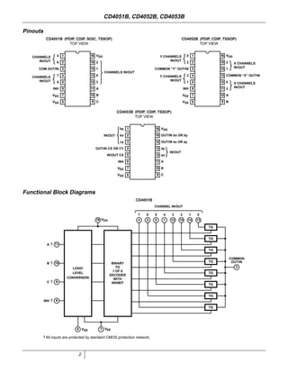

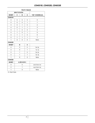
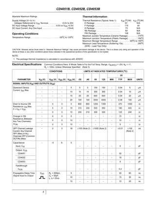

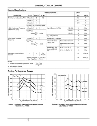
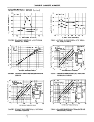
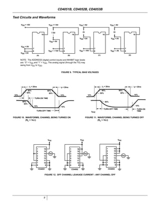
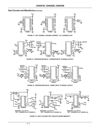

The document provides specifications for the CD4051B, CD4052B, and CD4053B CMOS analog multiplexer/demultiplexer integrated circuits from Texas Instruments. It describes their key features such as wide ranges for digital and analog signal levels, low ON resistance, high OFF resistance, and logic-level conversion. Tables provide truth tables, pinouts, maximum ratings, thermal information, and electrical specifications for the devices over temperature.


