Download to read offline
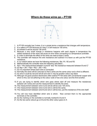

A PT100 temperature sensor has 3 wires to measure temperature based on resistance. It has a resistance of 100 ohms at 0 degrees Celsius that changes with temperature. The controller measures the resistance between wires to subtract the wire resistance and calculate the actual PT100 resistance, eliminating measurement errors from the wire resistance. To identify the wires, measure the resistance between each pair - the resistance between two wires will be over 100 ohms, and between the third wire will be low, identifying which is which.


