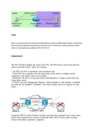
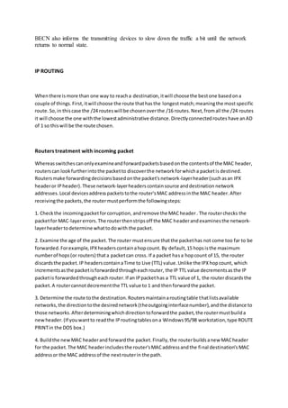
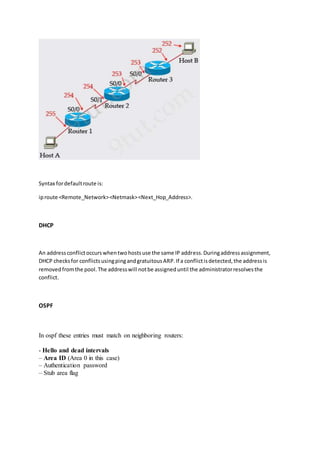
Download to read offline
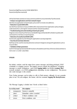


The document discusses several routing protocols including HSRP, GLBP, VRRP, SNMP, NetFlow, and syslog. It provides details on: - The virtual MAC addresses used by HSRP version 1 and 2. - The states an HSRP router can be in and how only one reaches the active state. - How GLBP elects an active virtual gateway and assigns virtual MAC addresses to members. - How VRRP can track interface status through tracked objects. - The framework and components of SNMP including managers, agents, MIBs, and PDUs. - What NetFlow tracks to identify flows and how it is used for tasks like monitoring, planning,