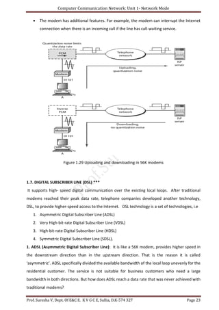
This document provides an overview of network models, including the OSI and TCP/IP models. It describes the seven layers of the OSI model and the functions of each layer. The four layers of the TCP/IP model are also explained, along with their relationship to the OSI layers. Key topics covered include data encapsulation, peer-to-peer communication between layers, and the responsibilities of the physical, data link, network, transport, and application layers.
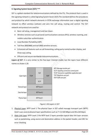
This document provides an overview of network models and addressing. It discusses layered network models including the OSI model and its seven layers (physical, data link, network, transport, session, presentation, application). It also discusses the TCP/IP protocol suite and how it maps to the OSI layers. The chapter covers addressing in networks including physical, logical, port, and specific addresses. Examples are provided to illustrate how addresses are used at different layers for communication between processes on different devices.
This document provides lecture notes on computer networks. It begins with an introduction to computer networks, defining them as interconnected autonomous computers that exchange information. It then discusses network models including the OSI reference model, which structures network communication across seven layers of abstraction. The document outlines the key concepts covered in each of the five units of an undergraduate course on computer networks.
The document provides answers to questions about computer networks. It defines a computer network as a collection of autonomous computers interconnected by a single technology that allows them to exchange information. It discusses different network topologies including bus, ring, star, tree, mesh, and hybrid and their advantages and disadvantages. It describes applications of computer networks like information access, communication, and entertainment. It explains the OSI 7-layer model and describes the functions and protocols of each layer. It defines local area networks (LANs), metropolitan area networks (MANs), and wide area networks (WANs) and provides examples of each.
This document proposes a model for classifying network troubleshooting issues according to the seven layers of the OSI model. It aims to standardize how network troubles are identified and expressed for more efficient network administration and troubleshooting. For each layer of the OSI model, the document categorizes the types of troubles that could occur on that layer. For example, on the Application layer troubles are divided into "Offline troubles" and "Online troubles", and on the Presentation layer they are divided into "Text troubles", "Audio troubles", and "Video-graphic troubles". The proposed model is intended to allow troubles to be identified at a more granular level for faster resolution of network issues.
The document discusses various topics related to computer networks including metropolitan area networks, wide area networks, wireless networks, home network categories, network software, protocol hierarchies, connection-oriented and connectionless services, service primitives, and reference models such as OSI and TCP/IP. It provides details on the seven layers of the OSI model including the functions and services provided by each layer.
The document discusses network models and layers. It covers the layered architecture of the Internet model and OSI model. The key points are:
1. The Internet and OSI models use a layered approach to break down the complex process of network communication into smaller, well-defined functions.
2. The Internet model has 5 layers - physical, data link, network, transport, and application. The OSI model adds an additional session layer and presentation layer.
3. Each layer only interacts with the layers directly above and below it, performing specific tasks like physical addressing, routing, and providing end-user services.
The document discusses the OSI reference model and TCP/IP reference model. It provides details on the 7 layers of the OSI model including the application, presentation, session, transport, network, data link, and physical layers. It also describes the layers of the TCP/IP model including the application, transport, internet, and data link/physical layers. The document compares the OSI and TCP/IP models and explains how data is encapsulated and transmitted using the TCP/IP protocol suite.
The Data Link Layer (DLL) is the second layer of the OSI model that establishes links between networked devices and ensures reliable data transmission. It performs framing to encapsulate data for transmission, uses addressing to label source and destination nodes, and implements error detection methods like CRC to verify accurate data delivery. The DLL is critical for enabling communication across a network.
The document discusses key concepts in networking including line configurations, topologies, network types, transmission modes, the hierarchical network model, and the OSI model. It provides details on the point-to-point and multipoint line configurations, five basic topologies (bus, star, ring, tree, mesh), three main network types (LAN, MAN, WAN), and three transmission modes (simplex, half-duplex, full-duplex). It also describes the three layers of Cisco's hierarchical network model (core, distribution, access) and the seven layers of the OSI model.
The document discusses the OSI model, which is a standard framework for network communication. It has 7 layers: physical, data link, network, transport, session, presentation, and application. Each layer has a specific role, with the lower layers focusing on physical connectivity and higher layers dealing with software interactions. The layered model allows for modularity and troubleshooting individual layers.
The document discusses the seven layers of the OSI model and their functions. It describes each layer from the physical layer to the application layer, explaining their main responsibilities in network communication. Some key points covered include that the OSI model divides network tasks into seven smaller sub-tasks, with each layer building on the layers below it and providing services to the layers above. The lower layers deal mainly with physical connectivity and data transmission while the upper layers are closer to the end user and deal with application-specific tasks.
The Open Systems Interconnection Basic Reference Model [OSI] is an abstract description for network protocol design, developer as an effort to standardize networking.
This document discusses several network topologies: bus, ring, star, mesh, tree, and hybrid. For each topology, it outlines the key features, advantages, and disadvantages. Bus topology uses a single cable connected to all devices, making it inexpensive but prone to single points of failure. Ring topology forms a closed loop between all devices, allowing for redundancy but adding complexity. Star topology connects all devices to a central hub, facilitating troubleshooting but relying on the hub. Mesh topology provides multiple connections between all devices for robustness but at increased cost. Tree and hybrid topologies combine aspects of other topologies to balance advantages against complexity and expenses.
The document discusses the OSI model, which is a standard framework for network communication. It divides network architecture into seven layers: physical, data link, network, transport, session, presentation, and application. Each layer only communicates with the layers directly above and below it and has a specific set of functions. This layered approach makes networks easier to design, troubleshoot, and maintain when changes are made. The physical layer deals with physical connections and bit transmission. The data link layer organizes bits into frames and controls flow. The network layer decides how data moves between networks. Higher layers ensure reliable and secure delivery of data between applications.
The document discusses the OSI model and IP model for networking. It provides details on the 7 layers of the OSI model including the application layer. It also describes the 4 layers of the IP model and highlights some of the differences between the OSI and IP models. References are provided for additional information on the OSI model, IP model, and their differences.
Data Link Layer, Error correction and detection like LRC, VRC, CRC, checksum and Hamming coding, Data link protocols, stop and wait ARQ, sliding window ARQ, Petrinet models, HDLC, etc
The document discusses the OSI Reference Model, which divides networking functions into 7 layers - physical, data link, network, transport, session, presentation, and application layer. Each layer has distinct responsibilities and provides services to the layer above it. The model was developed by ISO to standardize network communication and ensure compatibility between different systems.
In this presentation OSI Model of TCP/IP Explained with details of all seven layers of Transmission Control Protocol/ Internet Protocol.
Application layer
Presentation Layer
Session Layer
Transport Layer
Network Layer
Datalink Layer
Physical Layer
The document discusses network models, including the layered tasks model and the Internet model. It describes the five layers of the Internet model - physical, data link, network, transport, and application layers. Each layer is responsible for different functions, with the physical layer transmitting individual bits, the data link layer transmitting frames between nodes, the network layer delivering packets from source to destination, the transport layer providing reliable process-to-process message delivery, and the application layer providing services to users. Examples are given to illustrate how the layers work together to transmit data across networks. The OSI model is also mentioned as having seven layers.
A computer network document describes a 9th grade unit on computer networks and local area networks (LANs). It defines a computer network as a system of interconnected computers and devices connected by wires, cables or wireless links to share resources and exchange information. The document discusses different types of networks based on geographic scale (LANs, WANs) and topology (bus, ring, star, tree). It also describes common LAN devices like network interface cards, cables, hubs/switches, servers, and wireless network cards.
This document provides an introduction to data communications and computer networks. It defines key terms like telecommunications, data communications, and discusses the basic components of a data communication system including transmission medium and data flow types. It also defines what a computer network is, describes different physical structures for networks including topology types, and categories of networks like local area networks and wide area networks. Finally, it provides an overview of the Internet and its hierarchical organization, and defines what a communication protocol is and its key elements of syntax, semantics and timing.
This document discusses various network topologies including point-to-point, bus, star, ring, mesh, tree, and hybrid topologies. It describes the basic structure of each topology, how devices connect to each other, common uses, and strengths and weaknesses. For example, it explains that in a star topology all hosts connect to a central hub device via point-to-point connections, while in a tree topology the network is divided into multiple hierarchical levels with end devices connecting to access layers and layers connecting up to the core layer at the top. A hybrid topology combines elements of different topologies to inherit their advantages.
The document discusses the OSI reference model, which defines 7 layers of network communication: physical, data link, network, transport, session, presentation, and application. Each layer has a specific role, such as the physical layer being responsible for transmitting raw bits over a communication medium and the network layer handling routing between devices. The layered approach separates network functionality and allows different aspects of communication to be developed independently.
This document discusses network models and the OSI model. It describes the seven layers of the OSI model which are physical, data link, network, transport, session, presentation, and application. Each layer has a specific function like the physical layer is responsible for bit transmission between nodes, the data link layer handles frame transmission between nodes, the network layer handles packet delivery from source to destination host, etc. It also discusses the TCP/IP protocol suite and how it maps to the OSI layers. Finally, it covers the different addressing schemes used in TCP/IP including physical, logical, port, and specific addresses.
This document contains a student's assignment responses summarizing key aspects of data communication and the internet model. The student lists the layers of the internet model and describes the network support layers and user support layer. They explain peer-to-peer processes, how information passes between layers, and the purpose of headers and trailers. Responsibilities of various layers are provided, including differences between addresses. Correlations between OSI and internet layers are drawn.
This document discusses the OSI model and its 7 layers. It describes the layered architecture approach of breaking communication tasks into simpler sub-tasks handled by individual layers. Each layer provides services to the layer above and relies on the layer below. The layers are the physical, data link, network, transport, session, presentation, and application layers. Each layer has specific responsibilities for handling data transmission and communication functions.
The document summarizes the 7 layers of the OSI model established by the International Organization for Standardization (ISO) to standardize network communication. The layers are: 1) Physical, 2) Data Link, 3) Network, 4) Transport, 5) Session, 6) Presentation, and 7) Application. Each layer has a specific function, with the lower layers focusing on hardware-based functions like transmitting raw data, and higher layers focusing on software-based functions like process-to-process communication and application services.
The document discusses the 7-layer OSI model, which characterizes and standardizes communication functions across different systems to enable interoperability. It describes each of the 7 layers - physical, data link, network, transport, session, presentation, and application layer - and their respective roles and functions in managing the flow of data from one application to another. Each layer provides services to the layer above and receives services from the layer below, with layers 1-4 relating to communications technologies and layers 5-7 relating to user applications.
The document discusses communication architectures and protocol layers. It introduces the OSI reference model, which divides communication tasks into 7 layers - physical, data link, network, transport, session, presentation, and application layer. Each layer provides services to the layer above it and communicates with corresponding layers on other systems. The layers simplify complex communication tasks and allow standardized protocols for each layer.
OSI 7 layer Architecture and explain the functions of each layerAnanthkumar6965
The document explains the 7-layer OSI model for network communication. The OSI model decomposes communication into 7 layers, with each layer responsible for specific functions. The layers are: Physical (transmits raw bits), Data Link (frames bits into packets), Network (routes packets between nodes), Transport (delivers data reliably), Session (manages connections between applications), Presentation (translates between application and network formats), and Application (supports end-user network applications and services). The document describes the functions of each layer in detail.
This document provides an overview of network models, including layered tasks, the OSI model, and TCP/IP protocol suite. It discusses:
- The OSI model uses a seven-layer framework to allow communication between different computer systems. Each layer has specific responsibilities for encapsulating and delivering data.
- The TCP/IP protocol suite has five layers that correspond to the physical, data link, network, transport, and application layers of the OSI model. It uses both physical and logical addressing to deliver packets to devices and processes.
- Network communication involves four types of addressing - physical, logical, port, and specific addresses work together to deliver data across network layers.
This document provides an overview of protocols and standards. It defines a protocol as a set of rules for communication between entities in a system. Standards are agreed-upon protocols. Protocols are organized in hierarchies with multiple layers, where each layer offers services to the layer above it. Key elements of protocols include syntax, semantics, error handling, and sequencing. The document discusses two reference models - the OSI model with 7 layers and the TCP/IP model. The OSI layers are physical, data link, network, transport, session, presentation and application. The TCP/IP model has application, transport, internet, and network access layers.
The document discusses the Open Systems Interconnection (OSI) model, which defines seven layers of network communication. The seven layers are the physical, data link, network, transport, session, presentation, and application layers. Each layer has a specific function, with the lower layers dealing with physical connectivity and data transmission and the higher layers focusing on software applications and end-user interactions. The document provides details on the functions of each layer, such as the physical layer defining connections, signals, and topologies, the data link layer handling framing, addressing, and error control, and the transport layer providing service addressing, segmentation/reassembly, and connection control.
The document summarizes the seven layers of the OSI reference model:
1) The physical layer is responsible for physical connections between devices and defines characteristics like data rates and topology.
2) The data link layer frames data and ensures error-free transmission between nodes through flow control and error checking.
3) The network layer handles packet routing and logical addressing between independent networks.
4) The transport layer manages reliable data transfer through segmentation, reassembly, and connection control using TCP or UDP.
The document discusses network layer models including the OSI model and TCP/IP model. It provides details on each layer of the models and their functions. The OSI model has 7 layers - physical, data link, network, transport, session, presentation and application. The TCP/IP model combines some of these layers and has 5 layers - physical, data link, network, transport and application. Each layer is responsible for distinct networking functions and passes messages to the adjacent layers for delivery. [/SUMMARY]
The document discusses network models including the OSI model and TCP/IP model. It describes the seven layers of the OSI model and the four layers of the TCP/IP model. For each layer, it provides details on their functions and protocols. It also compares the OSI and TCP/IP models, noting they are both based on layered architectures but that the TCP/IP model combines some layers and better fits existing protocols.
The OSI Reference Model describes a 7-layer network architecture developed by ISO to standardize network communication globally. It defines separate protocols for each layer to define tasks and responsibilities. The physical layer is responsible for sending bits between systems by defining encoding, transmission rates, and hardware details. The data link layer provides error checking, frame creation, and hardware addressing. The network layer establishes logical connections between systems, performs routing, handles addressing, and switches packets between networks.
all about osi model and its layer which contain seven layer that is application ,presentation ,session ,transport ,networking, data link and physical layer . osi is appected by all and it was introduced by iso (indian standard organisation). osi is accepted by all over the world its best for networking which tell about all layer working .
The document describes the OSI reference model, which defines seven layers of network communication from the physical layer to the application layer. Each layer provides services to the layer above it and receives services from the layer below. The physical layer transmits raw bits of data and the application layer supports user applications. Between these layers are the data link layer, network layer, transport layer, session layer, and presentation layer, each of which performs specific functions to prepare data for transmission across a network. Protocols like TCP and IP operate at different layers to ensure reliable and ordered delivery of data packets from one device to another.
The document discusses embedded communication software design. It describes the OSI 7-layer model and how each layer is implemented in hardware and software. It then discusses different communication devices and how they implement specific layers, including hosts, switches, routers, and other telecommunication equipment. The document also covers the types of software components used, including protocol software and infrastructure/systems software, and considerations for communication software design.
The document summarizes the seven-layer OSI model. It describes each layer of the OSI model in detail, including the functions and responsibilities of the physical, data link, network, transport, session, presentation, and application layers. It explains that the OSI model divides network communication tasks into smaller and more manageable parts handled by different layers, with each layer building on the functions of those below it.
The OSI model is a conceptual model that characterizes and standardizes the functions of telecommunication systems without regard to their underlying internal structure. It defines seven layers of abstraction that partition the functions of transmitting data between open systems. Each layer serves the layer above it and is served by the layer below it. The layers are the physical, data link, network, transport, session, presentation, and application layers. The model was developed by ISO to establish international standards for network interconnection.
Advanced control scheme of doubly fed induction generator for wind turbine us...IJECEIAES
This paper describes a speed control device for generating electrical energy on an electricity network based on the doubly fed induction generator (DFIG) used for wind power conversion systems. At first, a double-fed induction generator model was constructed. A control law is formulated to govern the flow of energy between the stator of a DFIG and the energy network using three types of controllers: proportional integral (PI), sliding mode controller (SMC) and second order sliding mode controller (SOSMC). Their different results in terms of power reference tracking, reaction to unexpected speed fluctuations, sensitivity to perturbations, and resilience against machine parameter alterations are compared. MATLAB/Simulink was used to conduct the simulations for the preceding study. Multiple simulations have shown very satisfying results, and the investigations demonstrate the efficacy and power-enhancing capabilities of the suggested control system.
Literature Review Basics and Understanding Reference Management.pptxDr Ramhari Poudyal
Three-day training on academic research focuses on analytical tools at United Technical College, supported by the University Grant Commission, Nepal. 24-26 May 2024
ACEP Magazine edition 4th launched on 05.06.2024Rahul
This document provides information about the third edition of the magazine "Sthapatya" published by the Association of Civil Engineers (Practicing) Aurangabad. It includes messages from current and past presidents of ACEP, memories and photos from past ACEP events, information on life time achievement awards given by ACEP, and a technical article on concrete maintenance, repairs and strengthening. The document highlights activities of ACEP and provides a technical educational article for members.
Optimizing Gradle Builds - Gradle DPE Tour Berlin 2024Sinan KOZAK
Sinan from the Delivery Hero mobile infrastructure engineering team shares a deep dive into performance acceleration with Gradle build cache optimizations. Sinan shares their journey into solving complex build-cache problems that affect Gradle builds. By understanding the challenges and solutions found in our journey, we aim to demonstrate the possibilities for faster builds. The case study reveals how overlapping outputs and cache misconfigurations led to significant increases in build times, especially as the project scaled up with numerous modules using Paparazzi tests. The journey from diagnosing to defeating cache issues offers invaluable lessons on maintaining cache integrity without sacrificing functionality.
TIME DIVISION MULTIPLEXING TECHNIQUE FOR COMMUNICATION SYSTEMHODECEDSIET
Time Division Multiplexing (TDM) is a method of transmitting multiple signals over a single communication channel by dividing the signal into many segments, each having a very short duration of time. These time slots are then allocated to different data streams, allowing multiple signals to share the same transmission medium efficiently. TDM is widely used in telecommunications and data communication systems.
### How TDM Works
1. **Time Slots Allocation**: The core principle of TDM is to assign distinct time slots to each signal. During each time slot, the respective signal is transmitted, and then the process repeats cyclically. For example, if there are four signals to be transmitted, the TDM cycle will divide time into four slots, each assigned to one signal.
2. **Synchronization**: Synchronization is crucial in TDM systems to ensure that the signals are correctly aligned with their respective time slots. Both the transmitter and receiver must be synchronized to avoid any overlap or loss of data. This synchronization is typically maintained by a clock signal that ensures time slots are accurately aligned.
3. **Frame Structure**: TDM data is organized into frames, where each frame consists of a set of time slots. Each frame is repeated at regular intervals, ensuring continuous transmission of data streams. The frame structure helps in managing the data streams and maintaining the synchronization between the transmitter and receiver.
4. **Multiplexer and Demultiplexer**: At the transmitting end, a multiplexer combines multiple input signals into a single composite signal by assigning each signal to a specific time slot. At the receiving end, a demultiplexer separates the composite signal back into individual signals based on their respective time slots.
### Types of TDM
1. **Synchronous TDM**: In synchronous TDM, time slots are pre-assigned to each signal, regardless of whether the signal has data to transmit or not. This can lead to inefficiencies if some time slots remain empty due to the absence of data.
2. **Asynchronous TDM (or Statistical TDM)**: Asynchronous TDM addresses the inefficiencies of synchronous TDM by allocating time slots dynamically based on the presence of data. Time slots are assigned only when there is data to transmit, which optimizes the use of the communication channel.
### Applications of TDM
- **Telecommunications**: TDM is extensively used in telecommunication systems, such as in T1 and E1 lines, where multiple telephone calls are transmitted over a single line by assigning each call to a specific time slot.
- **Digital Audio and Video Broadcasting**: TDM is used in broadcasting systems to transmit multiple audio or video streams over a single channel, ensuring efficient use of bandwidth.
- **Computer Networks**: TDM is used in network protocols and systems to manage the transmission of data from multiple sources over a single network medium.
### Advantages of TDM
- **Efficient Use of Bandwidth**: TDM all
CHINA’S GEO-ECONOMIC OUTREACH IN CENTRAL ASIAN COUNTRIES AND FUTURE PROSPECTjpsjournal1
The rivalry between prominent international actors for dominance over Central Asia's hydrocarbon
reserves and the ancient silk trade route, along with China's diplomatic endeavours in the area, has been
referred to as the "New Great Game." This research centres on the power struggle, considering
geopolitical, geostrategic, and geoeconomic variables. Topics including trade, political hegemony, oil
politics, and conventional and nontraditional security are all explored and explained by the researcher.
Using Mackinder's Heartland, Spykman Rimland, and Hegemonic Stability theories, examines China's role
in Central Asia. This study adheres to the empirical epistemological method and has taken care of
objectivity. This study analyze primary and secondary research documents critically to elaborate role of
china’s geo economic outreach in central Asian countries and its future prospect. China is thriving in trade,
pipeline politics, and winning states, according to this study, thanks to important instruments like the
Shanghai Cooperation Organisation and the Belt and Road Economic Initiative. According to this study,
China is seeing significant success in commerce, pipeline politics, and gaining influence on other
governments. This success may be attributed to the effective utilisation of key tools such as the Shanghai
Cooperation Organisation and the Belt and Road Economic Initiative.
International Conference on NLP, Artificial Intelligence, Machine Learning an...gerogepatton
International Conference on NLP, Artificial Intelligence, Machine Learning and Applications (NLAIM 2024) offers a premier global platform for exchanging insights and findings in the theory, methodology, and applications of NLP, Artificial Intelligence, Machine Learning, and their applications. The conference seeks substantial contributions across all key domains of NLP, Artificial Intelligence, Machine Learning, and their practical applications, aiming to foster both theoretical advancements and real-world implementations. With a focus on facilitating collaboration between researchers and practitioners from academia and industry, the conference serves as a nexus for sharing the latest developments in the field.
KuberTENes Birthday Bash Guadalajara - K8sGPT first impressionsVictor Morales
K8sGPT is a tool that analyzes and diagnoses Kubernetes clusters. This presentation was used to share the requirements and dependencies to deploy K8sGPT in a local environment.
1. Computer Communication Network: Unit 1- Network Mode
Prof. Suresha V, Dept. Of E&C E. K V G C E, Sullia, D.K-574 327 Page 1
UNIT - 1- NETWORK MODELS
Learning Objectives:
Upon completion of this unit, the student should be able to:
Understand the need for computer communication networks.
Be familiar with the OSI and TCP/IP models.
Understand the responsibilities of each layer in OSI and TCP/IP models.
Discuss the types of addresses are used in TCP/IP protocols.
Understand telephone and cable networks used for data transmission.
Discuss the Signaling System Seven (SS7) used in networks.
Explains the different services offered by Telephone Networks.
Explains the Digital Subscriber Line (DSL) and its versions for ISDN services.
Discuss the most popular modems are available for data transmission.
1. Introduction :
Data communications and networking are changing the way we live. Computer Communication
Network (CCN) deals with four major concepts. They are
1. Data communications
2. Networking
3. Protocols and standards and
4. Networking models.
Networks exist so that data may be sent from one place to another-the basic concept of data
communications. Data communications between remote parties can be achieved through a
process called networking. Protocols and standards are vital to the implementation of data
communications and networking. Protocols refer to the set of rules and regulations; a standard
is a protocol that has been adopted by vendors and manufacturers. Network models serve to
organize, unify, and control the hardware and software components of data communications
and networking.
A network is a combination of hardware and software that sends data from one location to
another. The hardware consists of the physical equipment that carries signals from one point of
the network to another. The software consists of instruction sets that make possible the services
that we expect from a network. Computer networks are very complex object; hence it is
partitioned in to vertical set of levels, each level called layer.
2. Computer Communication Network: Unit 1- Network Mode
Prof. Suresha V, Dept. Of E&C E. K V G C E, Sullia, D.K-574 327 Page 2
1.1 Layered tasks: We use the concept of layers in our daily life. As an example, let us consider
two friends who communicate through postal mail. The process of sending a letter to a friend
would be complex if there were no services available from the post office. Figure 1.1 shows the
tasks involved in sending a letter
Figure 1.1 Tasks involved in sending a letter
The task includes a sender, a receiver, and a carrier that transports the letter. There is a
hierarchy of tasks. Higher Layer, Middle Layer and Lower Layer. Each layer performs specific
tasks and uses the services of the layer immediately below it.
1.2 The OSI Model: ***
It is a 7 layers model.
It is an Open Systems Interconnection model.
It was first introduced in the late 1970s.
OSI developed by International Standards Organization (ISO).
The purpose of the OSI model:
To show how to facilitate communication between different systems without requiring
changes to the logic of the underlying hardware and software.
The OSI model is not a protocol; it is a model for understanding and designing a network
architecture that is flexible, robust, and interoperable.
The OSI model is a layered framework for the design of network systems that allows
communication between all types of computer systems.
3. Computer Communication Network: Unit 1- Network Mode
Prof. Suresha V, Dept. Of E&C E. K V G C E, Sullia, D.K-574 327 Page 3
Layered Architecture: The OSI model is composed of seven layers:
1. Physical Layer
2. Data link Layer
3. Network Layer
4. Transport Layer
5. Session Layer
6. Presentation Layer and
7. Application Layer
The structure of seven layers in OSI model as shows figure 1.2
Figure 1.2 Seven layers of the OSI model
Layers are designed to identify which networking functions had related uses and collected those
functions into discrete groups that became the layers. The OSI model allows complete
interoperability between networks. The Each layer uses the services of the layer immediately
below it.
Peer-to-Peer Processes: Layer x on one machine communicates with layer x on another machine
called Peer-to-Peer Processes. This communication is governed by an agreed-upon series of rules
and conventions called protocols. Communication between machines is therefore a peer-to-peer
process using the protocols appropriate to a given layer, which is shown in figure 1.3.
Interfaces between Layers: Each interface defines what information and services a layer must
provide for the layer above it. Well defined interfaces and layer functions provide modularity to
a network.
4. Computer Communication Network: Unit 1- Network Mode
Prof. Suresha V, Dept. Of E&C E. K V G C E, Sullia, D.K-574 327 Page 4
Figure 1.3 The interaction between layers in the OSI model
Organizations of the layers: The seven layers can be thought of as belonging to three subgroups.
It allows interoperability among unrelated software systems
1. Network support layers : Physical (layer1), Data link (layer2), Network (layer3).
2. User support layers : Session (layer5), Presentation (layer6),Application (layer7)
3. Transport layer (Layer 4) : Links the above two layers subgroups
Data flow mechanism in OSI model: The figure 1.4 gives an overall view of the OSI layers.
Figure 1.4 An exchange using the OSI model
5. Computer Communication Network: Unit 1- Network Mode
Prof. Suresha V, Dept. Of E&C E. K V G C E, Sullia, D.K-574 327 Page 5
Data flow: D7 means the data unit at layer 7, D6 means the data unit at layer 6, and so on. The
process starts at layer 7 then moves from layer to layer in descending, sequential order. At each
layer, a header, or possibly a trailer, can be added to the data unit. Commonly, the trailer is
added only at layer 2. When the formatted data unit passes through the physical layer (layer 1),
it is changed into an electromagnetic signal and transported along a physical link. The reverse
process occurs in the receiver side and the message is again in a form appropriate to the
application and is made available to the recipient.
The data portion of a packet at level N-1 carries the whole packet from level N. The concept is
called “encapsulation”.
1.3 Layers in the OSI Model: This section briefly describes the functions of each layer in the
OSI model.
1. Physical Layer: It layer coordinates the functions required to transmit a bit stream over a
physical medium. It is responsible for movements of individual bits from one hop (node) to the
next. It deals with the mechanical and electrical specification of the primary connections like
cable, connectors etc.
Figure 1.5 Physical layer
Physical layer is concerned with the following:
• Physical characteristics of interfaces and medium: Types of medium and interfaces.
• Representation of bits: 1’s or 0’s Encoded in to Electrical or optical.
• Data rate: transmission rate: Speed in bps.
• Synchronization of bits: Both Transmitter and Receiver are in the same clock.
• Line configuration: Point to Point or Multipoint transmission.
• Physical topology: Way in which the network formed, ring bus, etc.
• Transmission mode: Simplex, Half or Full Duplex.
6. Computer Communication Network: Unit 1- Network Mode
Prof. Suresha V, Dept. Of E&C E. K V G C E, Sullia, D.K-574 327 Page 6
2. Data Link Layer: The data link layer is responsible for moving frames from one hop (node) to
the next hop.
Figure 1.6 Data link layer
Major duties of Data Link Layer:
Framing
Physical addressing
Flow control
Error control
Access control
Figure 1.7 illustrates hop-to-hop (node-to-node) delivery by the data link layer
Figure 1.7 Hop-to-Hop deliveries
As the figure 1.7 shows, communication at the DLL occurs between two adjacent nodes. To send
data from A to F, three partial deliveries are made. First, the DLL at A sends a frame to the DLL at
B (a router). Second, the data link layer at B sends a new frame to the data link layer at E. Finally,
7. Computer Communication Network: Unit 1- Network Mode
Prof. Suresha V, Dept. Of E&C E. K V G C E, Sullia, D.K-574 327 Page 7
the DLL at E sends a new frame to the DLL at F. Note that the frames that are exchanged
between the three nodes have different values in the headers. The frame from A to B has B as
the destination address and A as the source address. The frame from B to E has E as the
destination address and B as the source address. The frame from E to F has F as the destination
address and E as the source address.
3. Network Layer: It is responsible for the delivery of individual packets from the source host to
the destination host. Other responsibilities of network layer includes
Logical addressing
Routing
Figure 1.8 Network layer
Figure 1.9 illustrates end-to-end delivery by the network layer.
Figure 1.9 Source-to-destination delivery
8. Computer Communication Network: Unit 1- Network Mode
Prof. Suresha V, Dept. Of E&C E. K V G C E, Sullia, D.K-574 327 Page 8
4. Transport Layer: It is responsible for the delivery of a message from one process to another. A
process is an application program running on a host. It ensures that the whole message arrives
intact and in order, overseeing both error control and flow control at the source-to-destination
level.
Figure1.10 shows the relationship of the transport layer to the network and session layers.
Figure 1.10 Transport layer
Other responsibility of the transport layer includes the following:
1. Service-point addressing.
2. Segmentation and reassembly.
3. Connection control.
4. Flow control.
5. Error control.
Figure 1.11 Illustrates process-to-process delivery by the transport layer.
Figure 1.11 Reliable process-to-process delivery of a message
9. Computer Communication Network: Unit 1- Network Mode
Prof. Suresha V, Dept. Of E&C E. K V G C E, Sullia, D.K-574 327 Page 9
5. Session Layer: The session layer is responsible for dialog control and synchronization. Specific
responsibilities of the session layer include the following:
1 .Dialog control: The session layer allows two systems to enter into a dialog. It allows the
communication between two processes to take place in either half-duplex full-duplex mode.
2. Synchronization: The session layer allows a process to add checkpoints, or synchronization
points, to a stream of data
Figure 1.12 Session layer
6. Presentation Layer: The presentation layer is concerned with the syntax and semantics of the
information exchanged between two systems. Figure 1.13 shows the relationship between the
presentation layer and the application and session layers
Figure 1.13 Presentation layer
Specific responsibilities of the presentation layer are
1. Translation: Different computers use different encoding systems, the presentation layer is
responsible for interoperability between these different encoding methods. The presentation
layer at the sender changes the information from its sender-dependent format into a common
format. The presentation layer at the receiving machine changes the common format into its
receiver-dependent format.
10. Computer Communication Network: Unit 1- Network Mode
Prof. Suresha V, Dept. Of E&C E. K V G C E, Sullia, D.K-574 327 Page 10
2. Encryption: It ensures privacy for carry sensitive information by sending the information in
other form.
3. Compression: Data compression reduces the number of bits contained in the information. It
becomes particularly important in the transmission of multimedia such as text, audio, and video.
7. Application Layer: The application layer is responsible for providing services to the user.
Figure 1.14 Application layer
The major duties of the application:
Network virtual terminal: Enable to user for remote login
File transfer, access, and management
Mail services
Directory services
Summary of Layers :
Figure 1.15 Summary of layers
11. Computer Communication Network: Unit 1- Network Mode
Prof. Suresha V, Dept. Of E&C E. K V G C E, Sullia, D.K-574 327 Page 11
1.4 TCP / IP PROTOCOL SUITE (Transmission Control Protocol / Internet Protocol)***
TCP/IP is a hierarchical protocol made up of interactive modules, each of which provides a
specific functionality. TCP/IP protocol suite was defined as having four layers shown in fig 1.16
1. Host-To-Network.
2. Internet.
3. Transport and
4. Application.
Figure 1.16 TCP/IP and OSI model
In figure 1.16 TCP/IP is compared to OSI, Here host-to-network layer is equivalent to the
combination of the physical and data link layers. The internet layer is equivalent to the network
layer, and the application layer is roughly doing the job of the session, presentation, and
application layers with the transport layer in TCP/IP taking care of part of the duties of the
session layer.
TCP / IP PROTOCOL SUITE: It consists of four layers; they are
1. Host-To-Network
2. Internet,
3. Transport and
4. Application layers. This is shown in figure 1.17.
TCP / IP PROTOCOL layers description:
1. Host-to-network layer: In this layer TCP/IP does not define any specific protocol. It supports
all the standard and proprietary protocols. A network in a TCP/IP internetwork can be a local
area network (LAN) or a wide-area network (WAN).
12. Computer Communication Network: Unit 1- Network Mode
Prof. Suresha V, Dept. Of E&C E. K V G C E, Sullia, D.K-574 327 Page 12
Figure 1.17 TCP/IP and OSI model
2. Network Layer (IP layer): TCP/IP supports the Internetworking Protocol. IP uses four
supporting protocols: ARP, RARP, ICMP, and IGMP.
1. ARP (Address Resolution Protocol)
2. RARP (Reverse Address Resolution Protocol)
3. ICMP (Internet Control Message Protocol)
4. IGMP (Internet Group Message Protocol)
1. Internetworking Protocol (IP): It is an unreliable and connectionless protocol-a best-effort
delivery service. IP transports data in packets called datagram, each of which is transported
separately. Datagram’s can travel along different routes and can arrive out of sequence or
be duplicated. IP does not keep track of the routes and has no facility for reordering
datagram once they arrive at their destination.
2. Address Resolution Protocol (ARP): It is used to associate a logical address with a physical
address. ARP is used to find the physical address of the node when its Internet address is
known.
3. Reverse Address Resolution Protocol (RARP): It allows a host to discover its Internet address
when it knows only its physical address. It is used when a computer is connected to a
network for the first time or when a diskless computer is booted.
4. Internet Control Message Protocol (ICMP): It is a mechanism used by hosts and gateways to
send notification of datagram problems back to the sender. ICMP sends query and error
reporting messages.
5. Internet Group Message Protocol (IGMP): The Internet Group Message Protocol (IGMP) is
used to facilitate the simultaneous transmission of a message to a group of recipients.
13. Computer Communication Network: Unit 1- Network Mode
Prof. Suresha V, Dept. Of E&C E. K V G C E, Sullia, D.K-574 327 Page 13
3. Transport Layer: This layer was represented in TCP/IP by two protocols, TCP and UDP. These
protocols are responsible for delivery of a message from a process to another process.
a. UDP (User Datagram Protocol): It is a process-to-process protocol that adds only port
addresses, checksum error control, and length information to the data from the upper layer.
b. TCP (Transmission Control Protocol): It provides full transport-layer services to applications. It
is a reliable stream transport protocol. It gives connection-oriented: A connection must be
established between both ends services.
c. SCTP (Stream Control Transmission Protocol): It provides support for newer applications such
as voice over the Internet. It is a transport layer protocol that combines the best features of
UDP and TCP.
5.Application Layer: It support user interface with network. many protocols are defined at this
layer are:
HTTP(Hypertext Transfer Protocol):enables the connection between a web server
and a client
SMTP(Simple Mail Transfer Protocol): An electronic mail (e-mail) allows users to
send mails across an internet.
c FTP(File Transfer Protocol): Enables user to transfer the data file
DNS(Domain Naming System): client to remote login
TELNET : Tele communication protocol, VoIP
6. Comparison between OSI and TCP/IP Model
OSI Model TCP/IP MODEL
It is a 7 layers model It is a 4 layers model
Protocols are more hidden Protocols are less hidden
Model comes first and next protocol Protocol comes first and next Model
Each layer having less specific functionality Each layer having more specific
functionality
Supports both connection and connectionless
oriented services in network layer
It mainly supports connection less
services in network layer
Only connection oriented services in transport
layer
Both connection and connectionless
oriented services in transport layers
14. Computer Communication Network: Unit 1- Network Mode
Prof. Suresha V, Dept. Of E&C E. K V G C E, Sullia, D.K-574 327 Page 14
1.5 ADDRESSING***
Four levels of addresses are used in an internet employing the TCP/IP protocols:
1. Physical addresses
2. Logical addresses
3. Port addresses, and
4. Specific addresses
Figure1.17 Addresses in TCP/IP
1. Physical Addresses: It also known as the link address, is the address of a node as defined by
its LAN or WAN. It is included in the frame used by the data link layer. The physical addresses
have authority over the network (LAN or WAN).The size and format of these addresses vary
depending on the network.
Example 1.1: In Figure 1.19 a node with physical address 10 sends a frame to a node with
physical address 87. The two nodes are connected by a link. As the figure shows, the computer
with physical address 10 is the sender, and the computer with physical address 87 is the
receiver.
Figure 1.19 Physical addresses
Example 1.2: Most local-area networks use a 48-bit (6-byte) physical address written as 12
hexadecimal digits; every byte (2 hexadecimal digits) is separated by a colon, as shown below:
07:01:02:01:2C:4B
A 6-byte (12 hexadecimal digits) physical address.
15. Computer Communication Network: Unit 1- Network Mode
Prof. Suresha V, Dept. Of E&C E. K V G C E, Sullia, D.K-574 327 Page 15
2. Logical Addresses: Logical addresses are necessary for universal communications that are
independent of underlying physical networks. Physical addresses are not adequate in an
internetwork environment where different networks can have different address formats. A
universal addressing system is needed in which host can be identified uniquely, regardless of the
underlying physical network.
Example 1.3: Figure 1.20 shows a part of an internet with two routers connecting three LANs.
Each device has a pair of addresses (logical and physical) for each connection. In this case, each
computer is connected to only one link and therefore has only one pair of addresses. Each
router, however, is connected to three networks (only two are shown in the figure). So each
router has three pairs of addresses, one for each connection. The physical addresses will change
from hop to hop, but the logical addresses usually remain the same.
Figure 1.20 IP addresses
3. Port Addresses: The IP and the physical address are necessary for a quantity of data to travel
from a source to the destination host. The end object of Internet communication is a process
communicating with another process. For these processes to receive data simultaneously, we
need a method to label assigned to a process is called a port address. A port address in TCP/IP is
16 bits in length. The physical addresses will change from hop to hop, but the logical and port
addresses usually remain the same.
Example 1.4: Figure 1.21. Shows two computers communicating via the Internet. The sending
computer is running three processes at this time with port addresses a, b, and c. The receiving
computer is running two processes at this time with port addresses j and k. Process a in the
sending computer needs to communicate with process j in the receiving computer. Note that
16. Computer Communication Network: Unit 1- Network Mode
Prof. Suresha V, Dept. Of E&C E. K V G C E, Sullia, D.K-574 327 Page 16
although physical addresses change from hop to hop, logical and port addresses remain the
same from the source to destination.
Figure 1.21 Port addresses
Example 1.5: Port address is a 16-bit address represented by one decimal number as shown.
753
A 16-bit port address represented as one single number
4. Specific Addresses: Some applications have user-friendly addresses that are designed for that
specific address.
E-mail address
URL (Universal Resource Locator)
17. Computer Communication Network: Unit 1- Network Mode
Prof. Suresha V, Dept. Of E&C E. K V G C E, Sullia, D.K-574 327 Page 17
1.6 TELEPHONE NETWORK:
1. Introduction: It is beginnings in the late 1800s.Originally an analog system using analog
signals to transmit voice. The entire network, which is referred to as the plain old telephone
system (POTS).Telephone networks use circuit switching.
Telephone System:
Figure 1.22 Telephone system
Major components of Telephone System:
1. Local Loops: A twisted-pair cable that connects the subscriber telephone to the nearest end
office or local central office. Its B.W is 4 kHz for voice communication. The first three digits of a
local telephone number define the office, and the next four digits define the local loop number.
2. Trunks: Trunks are transmission media that handle the communication between offices. Trunk
normally handles hundreds or thousands of connections through multiplexing. transmission is
usually through optical fibers or satellite links.
3. Switching Offices: To avoid having a permanent physical link between any two subscribers,
the telephone company has switches located in a switching office. Switch connects several local
loops or trunks and allows a connection between different subscribers
2. Local-Access Transport Areas (LATAs): A LATA can be a small or large metropolitan area. A
small state may have one single LATA; a large state may have several LATAs. A LATA boundary
may overlap the boundary of a state; part of a LATA can be in one state, part in another state.
Two types of LATAs Services
a) Intra-LATA Services
b) Inter-LATA Services
a) Intra-LATA Services: The services offered by the common carriers (telephone companies)
inside a LATA are called intra-LATA services.
18. Computer Communication Network: Unit 1- Network Mode
Prof. Suresha V, Dept. Of E&C E. K V G C E, Sullia, D.K-574 327 Page 18
Figure 1.23 Switching offices in a LATA
The carrier that handles these services is called a local exchange carrier (LEC). Before the
Telecommunications Act of 1996 intra-LATA services were granted to one single carrier. This was
a monopoly. After 1996, more than one carrier could provide services inside a LATA. The carrier
that provided services before 1996 owns the cabling system (local loops) and is called the
Incumbent Local Exchange Carrier (ILEC).The new carriers that can provide services are called
Competitive Local Exchange Carriers (CLECs). CLECs would provide other services such as mobile
telephone service, toll calls inside a LATA, and so on. Communication inside a LATA is handled by
end switches and tandem switches. A call that can be completed by using only end offices is
considered toll-free. A call that has to go through a tandem office (intra-LATA toll office) is
charged.
b). Inter-LATA Services: The services between LATAs called Inter-LATA Services.
Figure 1.24 Point of Presences (POPs)
These services handled by Interexchange Carriers (IXCs).IXCs sometimes called long-distance
companies, provide communication services between two customers in different LATAs. Major
19. Computer Communication Network: Unit 1- Network Mode
Prof. Suresha V, Dept. Of E&C E. K V G C E, Sullia, D.K-574 327 Page 19
companies providing inter-LATA services include AT&TMCI, WorldCom, Sprint, Verizon etc. The
IXCs are long-distance carriers that provide general data communications services including
telephone service. A telephone call going through an IXC is normally digitized, with the carriers
using several types of networks to provide service. Each IXC that wants to provide inter LATA
services .in a LATA must have a POP in that LATA. The LECs that provide services inside the LATA
must provide connections so that every subscriber can have access to all POPs. Points of
Presence (POP): Point of presence (POP) connects several LECs and IXCs.
3. Signaling: It is used for information exchange concerning the establishment and control of a
telecommunication circuit & the management of the network, in contrast to user information
transfer. The signaling system was required to perform other tasks such as
Providing dial tone, ring tone, and busy tone.
Transferring telephone numbers between offices.
Maintaining and monitoring the call.
Keeping billing information.
Maintaining and monitoring the status of the telephone network equipment.
Providing other functions such as caller ID, voice mail, and so on.
In modern telephone networks the tasks of data transfer and signaling are separated:
Data transfer is done by one network, signaling by another, which is shown in figure 1.25
Figure1.25 Data transfer and signaling networks
20. Computer Communication Network: Unit 1- Network Mode
Prof. Suresha V, Dept. Of E&C E. K V G C E, Sullia, D.K-574 327 Page 20
4. Signaling System Seven (SS7) ***
SS7 is a global standard for telecommunications defined by the ITU. The protocol that is used in
the signaling network is called Signaling System Seven (SS7).The standard defines the procedures
and protocol by which network elements in PSTN exchange information over a digital signaling
network to effect wireless (cellular) and wire line call setup, routing and control. The SS7
network and protocol are used for:
Basic call setup, management and tear down.
Wireless services such as personal communications services (PCS), wireless roaming, and
mobile subscriber authentication.
Local Number Portability (LNP).
Toll-free (800/888) and toll (900) wireline services.
Enhanced call features such as call forwarding, calling party name/number display, and
three-way calling.
Efficient and secure worldwide telecommunications.
Layers of SS7: It is very similar to the five-layer Internet model, but the layers have different
names as shown 1.26
Figure 1.26 Layers in SS7
1. Physical Layer: MTP Level 1 The physical layer in SS7 called message transport part (MTP)
level I uses several physical layer specifications such as T-l (1.544 Mbps) and DCa (64 kbps).
2. Data Link Layer: MTP Level 2 the MTP level 2 layers provides typical data link layer services
such as packetizing, using source and destination address in the packet header, and CRC for
error checking.
21. Computer Communication Network: Unit 1- Network Mode
Prof. Suresha V, Dept. Of E&C E. K V G C E, Sullia, D.K-574 327 Page 21
3. Network Layer: MTP Level 3 The MTP level 3 layer provides end-to-end connectivity by using
the datagram approach to switching. Routers and switches route the signal packets from the
source to the destination.
4. Transport Layer: SCCP The signaling connection control point (SCCP) is used for special
services such as SaO-call processing.
5. Upper Layers: TUP, TCAP, and ISUP are three protocols at the upper layers.
a. Telephone user port (TUP) is responsible for setting up voice calls. It receives the dialed
digits and routes the calls.
b. Transaction capabilities application port (TCAP) provides remote calls that let an
application program on a computer invoke a procedure on another computer.
c. ISDN user port (ISUP) can replace TUP to provide services similar to those of an ISDN n/w
5. Services Provided by Telephone Networks: *** Telephone companies provide two types of
services: Analog and Digital.
1. Analog Services:
Analog Switched Services
800 service
Wide-area telephone service (WATS).
900 services
Analog Leased Service
2. Digital Services:
Switched/56 service.
Digital data service (DDS).
6. Dial Up Modems:
Traditional telephone lines can carry frequencies between 300 and 3300 Hz of BW 3000 Hz. This
range is used for transmitting voice. The effective bandwidth of a telephone line being used for
data transmission is 2400 Hz, covering the range from 600 to 3000 Hz, shown in figure 1.27
Figure 1.27 Telephone line bandwidth
22. Computer Communication Network: Unit 1- Network Mode
Prof. Suresha V, Dept. Of E&C E. K V G C E, Sullia, D.K-574 327 Page 22
MODEM: It is a device: a signal modulator and a signal demodulator. A modulator creates a
band pass analog signal from binary data. A demodulator recovers the binary data from the
modulated signal.
.
Figure 1.28 Modulation/demodulation
7. Modem Standards ***
Most popular modems available are based on the V-series standards published by the ITU-T
V.32 modem:
It uses a combined modulation and encoding technique called trellis-coded modulation.
The V.32 calls for 32-QAM with a baud rate of 2400.
Uses 4 bits of each symbol represent data; then total data rate is 4 x 2400 = 9600 bps.
V.32bis Modem:
It was the first of the ITU-T standards to support 14,400-bps transmission.
It uses 128-QAM transmission (7 bits/baud with I bit for error control) at a rate of 2400
baud (2400 x 6 = 14,400 bps.)
V.34bis Modem:
It provides a bit rate of 28,800 with a 960-point constellation
Bit rate of 33,600 bps with a 1664-point constellation
V.90 Modem
V.90 modems with a bit rate of 56,000 bps. Also called 56K modems.
These modems may be used only if one party is using digital signaling
They are asymmetric in that the downloading rate is a maximum of 56 kbps, while the
uploading rate can be a maximum of 33.6 kbps.
V.92 Modem
The standard above V90 is called V.92.
These modems can adjust their speed, and if the noise allows, they can upload data at
the rate of 48 kbps. The downloading rate is still 56 kbps.
23. Computer Communication Network: Unit 1- Network Mode
Prof. Suresha V, Dept. Of E&C E. K V G C E, Sullia, D.K-574 327 Page 23
The modem has additional features. For example, the modem can interrupt the Internet
connection when there is an incoming call if the line has call-waiting service.
Figure 1.29 Uploading and downloading in 56K modems
1.7. DIGITAL SUBSCRIBER LINE (DSL) ***
It supports high- speed digital communication over the existing local loops. After traditional
modems reached their peak data rate, telephone companies developed another technology,
DSL, to provide higher-speed access to the Internet. DSL technology is a set of technologies, i.e
1. Asymmetric Digital Subscriber Line (ADSL)
2. Very High-bit-rate Digital Subscriber Line (VDSL)
3. High-bit-rate Digital Subscriber Line (HDSL)
4. Symmetric Digital Subscriber Line (SDSL).
1. ADSL (Asymmetric Digital Subscriber Line): It is like a 56K modem, provides higher speed in
the downstream direction than in the upstream direction. That is the reason it is called
‘asymmetric’. ADSL specifically divided the available bandwidth of the local loop unevenly for the
residential customer. The service is not suitable for business customers who need a large
bandwidth in both directions. But how does ADSL reach a data rate that was never achieved with
traditional modems?
24. Computer Communication Network: Unit 1- Network Mode
Prof. Suresha V, Dept. Of E&C E. K V G C E, Sullia, D.K-574 327 Page 24
The existing local loops can handle bandwidths up to 1.1 MHz the entire 1.1 MHz is available
for data and voice communications. ADSL is an adaptive technology. The system uses a data rate
based on the condition of the local loop line.
1.1 Discrete Multitone Technique (DMT): The modulation technique that has become standard
for ADSL is called the Discrete Multitone Technique (DMT) which combines QAM and FDM.
Figure 1.30 Discrete multitone technique
There is no set way that the bandwidth of a system is divided. Each system can decide on its
bandwidth division. Figure 1.31: Bandwidth division in ADSL
Figure 1.31: Bandwidth division in ADSL
Typically, an available bandwidth of 1.104 MHz is divided into 256 channels. Each channel uses a
bandwidth of 4.312 kHz. The fig 1.30 shows how bandwidth can be divided into the following:
Voice: Channel 0 is reserved for voice communication.
Idle: Channels 1 to 5 are not used and provide a gap between voice and data communication.
Upstream data and control: Channels 6 to 30 (25 channels) are used for upstream data
transfer (24 channels) and 1 control. If there are 24 channels, each using 4 kHz (out of 4.312
25. Computer Communication Network: Unit 1- Network Mode
Prof. Suresha V, Dept. Of E&C E. K V G C E, Sullia, D.K-574 327 Page 25
kHz available) with QAM modulation. Upstream Data rate 24 x 4000 x 15, or a 1.44-Mbps.But
the data rate is normally below 500 kbps because some of the carriers are deleted at
frequencies where the noise level is large.
Downstream data and control: Channels 31 to 255 (225 channels) are used for downstream
data transfer and control. One channel is for control, and 224 channels are for data. If there
are 224 channels, then the data rate up to 224 x 4000 x 15, or13.4 Mbps. But in practice data
rate is normally below 8 Mbps, due to high noise in the some channel.
1.2 ADSL Implementation: 1. Customer Site: ADSL Modem (down link)
ADSL modem is located in customer site, like home or office buildings. This is shown in
figure 1.32
Figure 1.32: ADSL modem
ADSL modem installed at a customer's site. The local loop connects to a splitter which
separates voice and data communications. The ADSL modem modulates and demodulates the
data, using DMT, and creates downstream and upstream channels.
1.3 Telephone Company Site: DSLAM (uplink):
Figure 1.33: DSLAM
At the telephone company site, Instead of an ADSL modem, a device called a digital subscriber
line access multiplexer (DSLAM) is installed; it packetizes the data to be sent to the Internet.
26. Computer Communication Network: Unit 1- Network Mode
Prof. Suresha V, Dept. Of E&C E. K V G C E, Sullia, D.K-574 327 Page 26
1.4 ADSL Lite:
It is a splitter less ADSL, since the installation of splitters at the border of the user
premises expensive and impractical.
This technology allows an ASDL Lite modem to be plugged directly into a telephone jack
and connected to the computer.
The splitting is done at the telephone company. It uses 256 DMT carriers with 8-bit
modulation.
It can provide a maximum downstream data rate of 1.5 Mbps and an upstream data rate
of 512 kbps.
3. High-bit-rate Digital Subscriber Line (HDSL)
It was designed as an alternative to the T-1 line.
HDSL uses 2B1Q encoding which is less susceptible to attenuation.
A data rate of 1.544 Mbps can be achieved without repeaters up to a distance of 12,000
ft (3.86 km).
HDSL uses two twisted pairs (one pair for each direction) to achieve full-duplex
transmission.
4. Symmetric Digital Subscriber Line (SDSL).
The symmetric digital subscriber line (SDSL) is a one twisted-pair version of HDSL.
It provides full-duplex symmetric communication supporting up to 768 kbps in each
direction.
Although this feature meets the needs of most residential subscribers, it is not suitable
for residential subscribers that send and receive data in large volumes in both directions.
Table below shows a summary of DSL technologies: Note: Two-binary, one-quaternary (2B1Q)
27. Computer Communication Network: Unit 1- Network Mode
Prof. Suresha V, Dept. Of E&C E. K V G C E, Sullia, D.K-574 327 Page 27
1.8 CABLE TV NETWORKS: The cable TV network started as a video service provider, but it
has moved to the business of Internet access. Two types
1. Traditional Cable Networks
2. Hybrid Fiber-Coaxial (HFC) Network
1. Traditional Cable Networks: It was called community antenna TV (CATV) because an antenna
at the top of a tall hill or building received the signals from the TV stations and distributed them,
via coaxial cables, to the community. Figure 1.34 shows a schematic diagram of a traditional
cable TV network. Communication in the traditional cable TV network is unidirectional
Figure 1.34 Traditional cable TV networks
2. Hybride Fibre-Coaxial (HFC) Network : It is a second generation of cable networks.
Figure 1.35 Hybrid fiber-coaxial (HFC) network
The network uses a combination of fiber-optic and coaxial cable. The transmission medium from
the cable TV office to a box, called the fiber node, is optical fiber; from the fiber node through
the neighborhood and into the house is still coaxial cable. Figure 1.35 shows a schematic
diagram of an HFC network. The Regional Cable Head (RCH) normally serves up to 400,000
28. Computer Communication Network: Unit 1- Network Mode
Prof. Suresha V, Dept. Of E&C E. K V G C E, Sullia, D.K-574 327 Page 28
subscribers. The RCHs feed the distribution hubs, each of which serves up to 40,000 subscribers.
Modulation and distribution of signals are done in the distribution hub; the signals are then fed
to the fiber nodes through fiber-optic cables. The fiber node splits the analog signals so that the
same signal is sent to each coaxial cable. Each coaxial cable serves up to 1000 subscribers. The
use of fiber-optic cable reduces the need for amplifiers down to eight or less. Communication in
an HFC cable TV network can be bidirectional.
1.8.1 Cable TV for Data Transfer: Cable companies are now competing with telephone compa -
nies for the residential customer who wants high-speed data transfer. This section deals with
1. Bandwidth
2. Sharing.
3. CM and CMTS
4. Data Transmission Schemes: Data Over Cable System Interface Specification (DOCSIS).
1. Bandwidth: The coaxial cable has a bandwidth that ranges from 5 to750 MHz (approx).
To provide Internet access, the cable company has divided this bandwidth into three bands:
1. Video
2. Downstream data
3. Upstream data bands. Shown in fig 1.36
Figure 1.36: Division of coaxial cable band by CATV
Downstream Video Band:
It occupies frequencies from 54 to 550 MHz.
Each TV channel occupies 6 MHz; this can accommodate more than 80 channels.
Downstream Data Band
It occupies the upper band, from 550 to 750 MHz
This band is also divided into 6-MHz channels.
Modulation Downstream data band uses the 64-QAM modulation technique.
The theoretical downstream data rate is 30 Mbps.
29. Computer Communication Network: Unit 1- Network Mode
Prof. Suresha V, Dept. Of E&C E. K V G C E, Sullia, D.K-574 327 Page 29
Upstream Data Band:
It occupies the lower band, from 5 to 42 MHz
This band is also divided into 6-MHz channels.
Upstream data are modulated using the QPSK modulation technique due to high noise.
Data Rate is 12 Mbps, upstream data can be sent at (2 bits/Hz x 6 MHz).
2. Sharing: Both upstream and downstream bands are shared by the subscribers.
Upstream Sharing: The upstream data bandwidth is 37 MHz. Only six 6-MHz channels available
in the upstream direction. A subscriber needs to use one channel to send data in the upstream
direction. The question is, "How can six channels be shared in an area with 1000, 2000, or
even100, 000 subscribers?" The solution is timesharing.
Downstream Sharing: The downstream band has 33 channels of 6 MHz. A cable provider
probably has more than 33 subscribers; therefore, each channel must be shared between a
group of subscribers
3. CM and CMTS:*** To use a cable network for data transmission, need two key devices:
1. Cable Modem(CM)
2. Cable Modem Transmission System (CMTS).
1. The cable modem (CM): It is installed on the subscriber premises. It is similar to an ADSL
modem, as shown in figure 1.37.
Figure 1.37 Cable modem (CM)
2. Cable Modem Transmission System (CMTS): The cable modem transmission system (CMTS) is
installed inside the distribution hub by the cable company. It receives data from the Internet
and passes them to the combiner, which sends them to the subscriber. The CMTS also receives
30. Computer Communication Network: Unit 1- Network Mode
Prof. Suresha V, Dept. Of E&C E. K V G C E, Sullia, D.K-574 327 Page 30
data from the subscriber and passes them to the Internet. Figure 1.38 shows the location of the
CMTS.
Figure 1.38 Cable modem transmission system (CMTS)
4. Data Transmission Schemes: DOCSIS: Multimedia Cable Network Systems (MCNS) designed to
create a standard for data transmission over an HFC network called “Data Over Cable System
Interface Specification “(DOCSIS). DOCSIS defines all the protocols need to transport data from a
CMTS to a CM.
Upstream Communication: The following is a very simplified version of the protocol defined by
DOCSIS for upstream communication. It describes the steps that must be followed by a CM:
1. The CM checks the downstream channels for a specific packet periodically sent by the CMTS.
2. The packet asks any new CM to announce itself on a specific upstream channel.
3. The CMTS sends a packet to the CM, defining its allocated downstream and upstream
channels.
4. The CM then starts a process, called ranging, which determines the distance between the CM
and CMTS. This process is required for synchronization between all CMs and CMTSs for the
minislots used for timesharing of the upstream channels.
5. The CM sends a packet to the ISP, asking for the Internet address.
6. The CM and CMTS then exchange some packets to establish security parameters, which are
needed for a public network such as cable TV.
7. The CM sends its unique identifier to the CMTS.
8. Upstream communication can start in the allocated upstream channel; the CM can contend
for the mini-slots to send data.
Downstream Communication: In the downstream direction, the communication is much simpler.
There is no contention because there is only one sender. The CMTS sends the packet with the
address of the receiving CM, using the allocated downstream channel.
31. Computer Communication Network: Unit 1- Network Mode
Prof. Suresha V, Dept. Of E&C E. K V G C E, Sullia, D.K-574 327 Page 31
SUMMARY OF UNIT ONE: NETWORK MODELS
The ISO created a model called the OSI, which allows diverse systems to communicate.
The seven-layer OSI model provides guidelines for the development of universally
compatible networking protocols.
The physical, data link, and network layers are the network support layers.
The session, presentation, and application layers are the user support layers.
The transport layer links the network support layers and the user support layers.
The physical layer coordinates the functions required to transmit a bit stream over a physical
medium.
The data link layer is responsible for delivering data units from one station to the next
without errors.
The network layer is responsible for the source-to-destination delivery of a packet across
multiple network links.
The transport layer is responsible for the process-to-process delivery of the entire message.
The session layer establishes, maintains, and synchronizes the interactions between
communicating devices.
The presentation layer ensures interoperability between communicating devices through
transformation of data into a mutually agreed upon format.
The application layer enables the users to access the network.
TCP/IP is a five-layer hierarchical protocol suite developed before the OSI model.
The TCP/IP application layer is equivalent to the combined session, presentation, and
application layers of the OSI model.
Four levels of addresses are used in an internet following the TCP/IP protocols: physical (link)
addresses, logical (IP) addresses, port addresses, and specific addresses.
The physical address, or link address, is the address of a node as defined by its LAN or WAN.
The IP address uniquely defines a host on the Internet.
The port address identifies a process on a host.
Specific address is a user-friendly address.
The telephone, which is referred to as the plain old telephone system (POTS), was originally
an analog system. During the last decade, the telephone network has undergone many
technical changes. The network is now digital as well as analog.
The telephone network is made of three major components: local loops, trunks, and
switching offices.
It has several levels of switching offices such as end offices, tandem offices, and regional
offices.
32. Computer Communication Network: Unit 1- Network Mode
Prof. Suresha V, Dept. Of E&C E. K V G C E, Sullia, D.K-574 327 Page 32
The Telephone service called LATAs. The services offered inside a LATA are called intra-LATA
services. The carrier that handles these services is called a local exchange carrier (LEC).
In in-band signaling, the same circuit is used for both signaling and data.
In out-of- band signaling, a portion of the bandwidth is used for signaling and another
portion for data.
The protocol that is used for signaling in the telephone network is called Signaling System
Seven (SS7).
Telephone companies provide two types of services: analog and digital. We can categorize
analog services as either analog switched services or analog leased services.
The two most common digital services are switched/56 service and digital data Service
(DDS).
Data transfer using the telephone local loop was traditionally done using a dial-up modem.
The term modem is a composite word that refers to: a signal modulator and a signal
demodulator.
Most popular modems available are based on the V-series standards. The V.32 modem has a
data rate of 9600 bps. The V32bis modem supports 14,400-bps transmission.
V90 modems, called 56K modems, with a downloading rate of 56 kbps and uploading rate of
33.6 kbps are very common. The standard above V90 is called V92.
These modems can adjust their speed, and if the noise allows, they can upload data rate of
48 kbps.
Telephone companies developed another technology, digital subscriber line (DSL), to provide
higher-speed access to the Internet. DSL technology is a set of technologies, each differing in
the first letter (ADSL, VDSL, HDSL, and SDSL. ADSL provides higher speed in the downstream
direction than in the upstream direction
The high-bit rate digital subscriber line (HDSL) was designed as an alternative to the T-l line
(1.544 Mbps). The symmetric digital subscriber line (SDSL) is a one twisted- pair version of
HDSL.
The very high-bit-rate digital subscriber line (VDSL) is an alternative approach that is similar
to ADSL.
Community antenna TV (CATV) was originally designed to provide video services for the
community. The traditional cable TV system used coaxial cable end to end.
The second generation of cable networks is called a hybrid fiber-coaxial (HFC) n/w. The
network uses a combination of fiber-optic and coaxial cable.
Cable companies are now competing with telephone companies for the residential
Customer who wants high-speed access to the Internet.
To use a cable network for data transmission, we need two key devices: a cable modem (CM)
and a cable modem transmission system (CMTS).
33. Computer Communication Network: Unit 1- Network Mode
Prof. Suresha V, Dept. Of E&C E. K V G C E, Sullia, D.K-574 327 Page 33
UNIT -1 NETWORK MODEL QUESTION BANK
1. List the layers of the Internet model.
2. Which layers in the Internet model are the network support layers?
3. Which layer in the Internet model is the user support layer?
4. What is the difference between network layer delivery and transport layer delivery?
5. What is a peer-to-peer process?
6. How does information get passed from one layer to the next in the Internet model?
7. What are headers and trailers, and how do they get added and removed?
8. What are the concerns of the physical layer in the Internet model?
9. What are the responsibilities of the data link layer in the Internet model?
10. What are the responsibilities of the network layer in the Internet model?
11. What are the responsibilities of the transport layer in the Internet model?
12. What is the difference between a port address, a logical address, and a physical address?
13. Name some services provided by the application layer in the Internet model.
14. How do the layers of the Internet model correlate to the layers of the OSI model?
15. How are OSI and ISO related to each other?
16. Match the following to one or more layers of the OSI model:
a. Route determination
b. Flow control
c. Interface to transmission media
d. Provides access for the end user
17. Match the following to one or more layers of the OSI model:
a. Reliable process-to-process message delivery
b. Route selection
c. Defines frames
d. Provides user services such as e-mail and file transfer
e. Transmission of bit stream across physical medium
18. Match the following to one or more layers of the OSl model:
a. Communicates directly with user's application program
b. Error correction and retransmission
c. Mechanical, electrical, and functional interface
d. Responsibility for carrying frames between adjacent nodes
34. Computer Communication Network: Unit 1- Network Mode
Prof. Suresha V, Dept. Of E&C E. K V G C E, Sullia, D.K-574 327 Page 34
19. Match the following to one or more layers of the OSI model:
a. Format and code conversion services
b. Establishes, manages, and terminates sessions
c. Ensures reliable transmission of data
d. Log-in and log-out procedures
e. Provides independence from differences in data representation
20. What are the three major components of a telephone network?
21. Give some hierarchical switching levels of a telephone network.
22. What is LATA? What are intra-LATA and inter-LATA services?
23. Describe the SS7 service and its relation to the telephone network.
24. What are the two major services provided by telephone companies in the United States?
25. What is dial-up modem technology? List some of the common modem standards and their
data rates.
26. What is DSL technology? What are the services provided by the telephone companies using
DSL? Distinguish between a DSL modem and a DSLAM.
27. Compare and contrast a traditional cable network with a hybrid fiber-coaxial network.
28. How data transfer is achieved using CATV channels?
29. Distinguish between CM and CMTS.
30. Why circuit-switching was chosen for telephone networks?
31. Define end-to-end addressing in a telephone network when two parties communicate.
32. When we have an overseas telephone conversation, we sometimes experience a delay. Give
the reason?
33. Draw a bar chart to compare the different downloading data rates of common modems.
34. Draw a bar chart to compare the different downloading data rates of common DSL
technology implementations (use minimum data rates).
35. Calculate the minimum time required to download one million bytes of information using
each of the following technologies:
a. V32 modem
b. V32bis modem
c. V90 modem
36. Repeat Exercise 17 using different DSL implementations (consider the minimum rates).
37. Repeat Exercise 17 using a cable modem (consider the minimum rates).
38. What type of topology is used when customers in an area use DSL modems for data transfer
purposes? Explain.
35. Computer Communication Network: Unit 1- Network Mode
Prof. Suresha V, Dept. Of E&C E. K V G C E, Sullia, D.K-574 327 Page 35
UNIT 1- NETWORK MODEL- SOLVED EXAMPLES
1. Match the following to one or more layers of the OSI model:
a. Route determination – Network Layer
b. Flow control- Data Link Layer
c. Interface to transmission media- Physical Layer
d. Provides access for the end user- Application layer
2. Match the following to one or more layers of the OSI model:
a. Reliable process-to-process message delivery – Transport Layer
b. Route selection - Network Layer
c. Defines frames - Data Link Layer
d. Provides user services such as e-mail and file transfer- Application layer
e. Transmission of bit stream across physical medium - Physical Layer
3. Match the following to one or more layers of the OSl model:
a. Communicates directly with user's application program- Transport Layer
b. Error correction and retransmission - Transport Layer
c. Mechanical, electrical, and functional interface - Physical Layer
d. Responsibility for carrying frames between adjacent nodes - Data Link Layer
4. Match the following to one or more layers of the OSI model:
a. Format and code conversion services - Presentation Layer
b. Establishes, manages, and terminates sessions – session layer
c. Ensures reliable transmission of data - Data link and transport layers
d. Log-in and log-out procedures - session layer
e. Provides independence from differences in data representation - Presentation Layer
5. Calculate the minimum time required to download one million bytes of information using
each of the following technologies:
a. V32 modem
b. V32bis modem
c. V90 modem
d. ADSL modem
e. Cable modem
36. Computer Communication Network: Unit 1- Network Mode
Prof. Suresha V, Dept. Of E&C E. K V G C E, Sullia, D.K-574 327 Page 36
Solution:
(a). V.32 modem :
It has data rate of 9600bps
Minimum time required to down load = Data size / data rate
= (10, 00, 000 / 9600) Χ 8
= 834 seconds
= 13 min 54 sec
(b). V.32 bis modem :
It has data rate of 14,400 bps
Minimum time required to down load = Data size / data rate
= (10, 00, 000 / 14,400) Χ 8
= 556 seconds
= 9 min 16 sec
(b). V.90 modem :
It has data rate of 56,000 bps
Minimum time required to down load = Data size / data rate
= (10, 00, 000 / 56,000) Χ 8
= 143 seconds
= 2 min 23 sec
(b). ADSL modem :
It has data rate of 13.4 Mbps
Minimum time required to down load = Data size / data rate
= (10, 00, 000 / 13.4 Χ 106
) Χ 8
= 0.596 seconds
(b). Cable TV modem :
It has data rate of 30 Mbps
Minimum time required to down load = Data size / data rate
= (10, 00, 000 / 30 Χ 106
) Χ 8
= 0.266 seconds
37. Computer Communication Network: Unit 1- Network Mode
Prof. Suresha V, Dept. Of E&C E. K V G C E, Sullia, D.K-574 327 Page 37
UNIT 1- NETWORK MODEL
UNIVERSITY QUESTIONS AND ANSWER
1 a. Show the layer representation in the TCP/IP model and the OSI model and explain.
(Dec 09/ Jan 10 – 10marks –Answer refer page no. 2 and 11)
b. Give a brief overview of SS7 signaling. (Dec 09/ Jan 10 – 05marks –Ans refer page no.18)
c. Match the following functions to the appropriate layers in the OSI model.
(Dec 09/ Jan 10 – 05marks)
I. Dividing the transmitted bit stream into frames: Answer- Data Link Layer
II. Determining the route to be used through the subnet: Answer- Network Layer
III. Reliable process to process message delivery: Answer- Transport Layer
IV. Format and code conversion services: Answer- Presentation Layer
V. Accessing the World Wide Web: Answer- Application Layer
2 a. Explain OSI model, with a neat diagram. Consider a source, destination machine and some
intermediate nodes for discussion.(May/ June 10 – 10marks –Ans refer page no.3 to 5)
b. How addresses employed (used) in internet employing TCP/IP protocol can be classified?
(May/ June 10 – 02 marks –Answer refer page no.13 to 15)
c. What is DSL technology? List different DSL’s available. Discuss salient feature of ASDL.
(May/ June 10 – 08marks –Answer refer page no.22 and 23)
3 a. What are the levels of addresses that are used in internet, employing the TCP/IP protocols?
(December 10 – 10marks –Answer refer page no.13 to 15)
b. What are different types of services provided by telephone networks? (December 10 –
06marks –Answer refer page no.20)
c. Name the major components of a telephone network. (December 10 – 04marks –Answer
refer page no.16)
4 a. With a neat diagram, explain the TCP/IP reference model, giving a brief description of the
protocols in each layer (June/July 2011 – 10marks –Answer refer page no.11)
b. Differentiate between CM and CMTS. (June/July 2011 – 04marks –Ans refer page no.28)
c. Explain the operation of ADSL using discreet multi one modulations indicating the different
channels, with a neat diagram. (June/July 2011 – 06marks –Answer refer page no.22 &23)
38. Computer Communication Network: Unit 1- Network Mode
Prof. Suresha V, Dept. Of E&C E. K V G C E, Sullia, D.K-574 327 Page 38
5 a. Explain the difference between OSI reference model and TCP/IP reference model
(December 2011 – 05marks –Answer refer page no.13)
b. Match the following to one or more layers in OSI model: (December 2011 – 05marks)
i. Route determination: Answer- Network Layer
ii. Flow control: Answer- Transport Layer
iii. Interface to transmission media: Answer- Physical Layer
iv. Provides access for end user: Answer- Application Layer
v. Format and code conversion services: Answer- Presentation Layer
c. What is DSL technology? What are the services provided by the telephone companies using
DSL? Distinguish between DSL and DSLAM (December 2011 – 10marks –Answer refer
page no.22 and 23)
6. a. Describe the ISO OSI reference model of a computer network. Discuss the function of
Each layer. (December 2012 – 10 marks –Answer refer page no.2 and 5)
b. Describe the SS7 service and its relation to the telephone network. (December 2012 –
05marks –Answer refer page no.19 and 20)
c. Distinguish between a DSL modem and a DSLAM. December 2012 – 05marks –Answer
refer page no.22)
7.(a) Explain briefly with relevant examples, the 4 levels of address that are used in an internet
employing the TCP/IP Protocols.( June/July 2013 – 10marks –Ans refer page no. 13)
(b). Briefly describe the function of physical layer and data link layer ( June /July 2013 –
06 marks –Answer refer page no.5 and 6 )
(c).Explain the operation of ADSL using Discrete Multitone Technique indicating the different
channels with diagram.( June/July 2013 – 04 marks –Answer refer page no.24 )